

Page 1
CEP series
Multi-zone Amplier
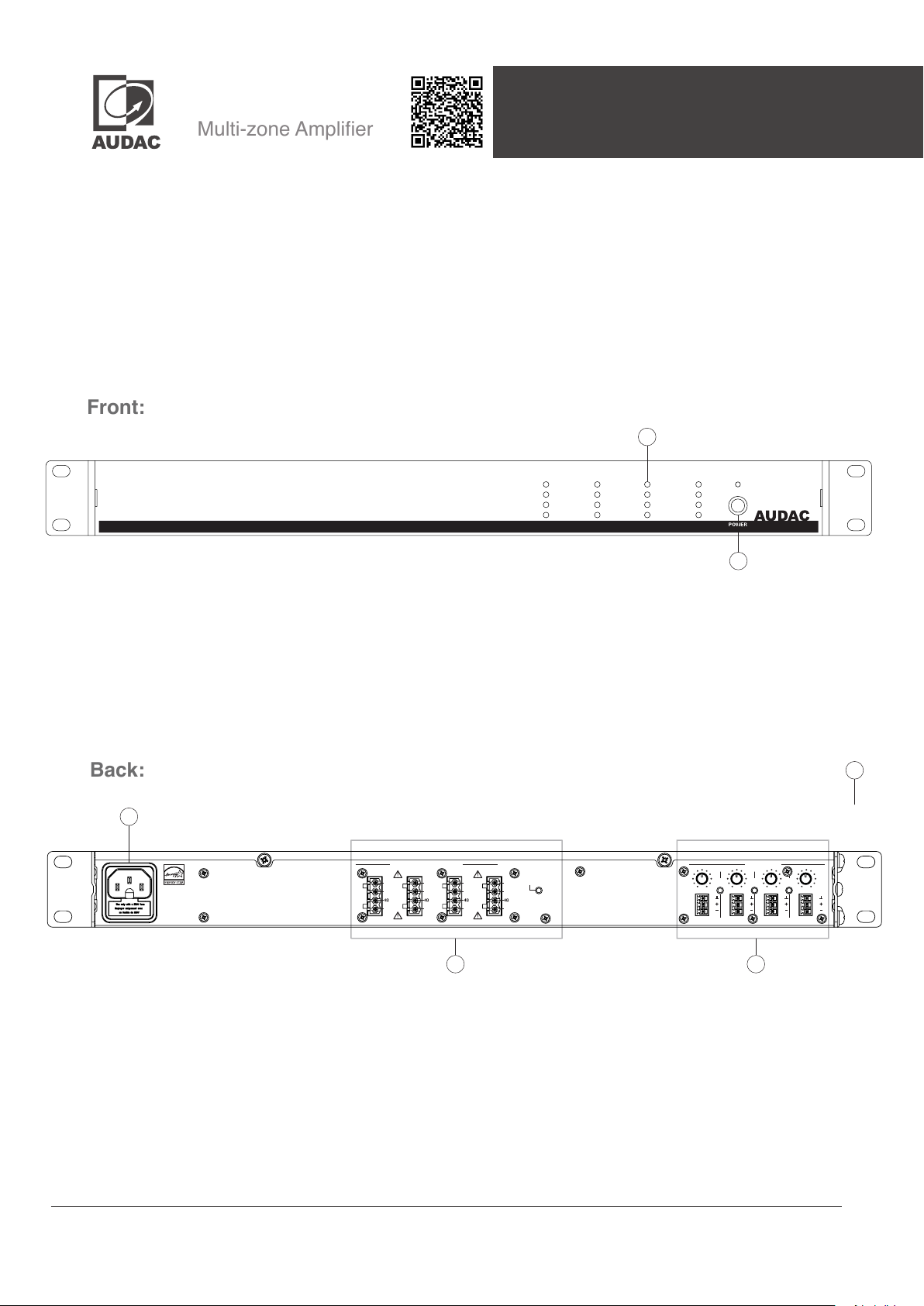
Front:
Back:
Quick start guide
The quick start guide gives you an overview of all the front and rear panel controls and connections on the
CEP series ampliers. The CEP series include the CEP408 (4 x 80 Watt) and the CEP 803 (8 x 30 Watt).
It allows you to get started with the installation of it in your project.
To get a detailed explanation of all functions, please check the complete manual which is available on the
web page https://manuals.audac.eu/CEP408 or scan the QR code as shown on top of this page.
1
ON
Prot
Clip
-10dB
Sig
CH 1 CH 2 CH 3 CH 4
Prot
Clip
-10dB
Sig
Prot
Clip
-10dB
Sig
Prot
Clip
-10dB
Sig
CEP408
1) Indicator LED (VU):
The (VU) indicator leds indicate the output level and status
of the amplier (Signal / -10dB / Clip / Protect).
1
SPEAKER OUTPUT
CH 4 CH 3 CH 2 CH 1
100V
70V
COM
2) Power switch with LED:
Allows to power the system ON and OFF. The indicator LED
illuminates in blue when switched ON. When switched to
standby (energy-saving) mode, the power LED will illuminate
in orange colour. The amplier switches automatically to
standby mode when no signal is available for 30 minutes.
Auto
100V
100V
70V
70V
COM
COM
3 4
Standby
100V
70V
COM
2
2
INPUT
LINK
LINK
4/3
LINK
3/2
2/1
Input adj.Input adj.Input adj.I nput adj.
CH 1CH 2CH 3CH 4
1) AC Power inlet:
The mains power supply (100-240V AC - 50/60 Hz) has
to be applied to this AC power inlet. The connection is
made by an IEC C14 power connector.
2) Rackspace enclosure
The CEP series is equipped with mounting options for a 19”
1HE rackspace.
audac.euCEP series
Page 2
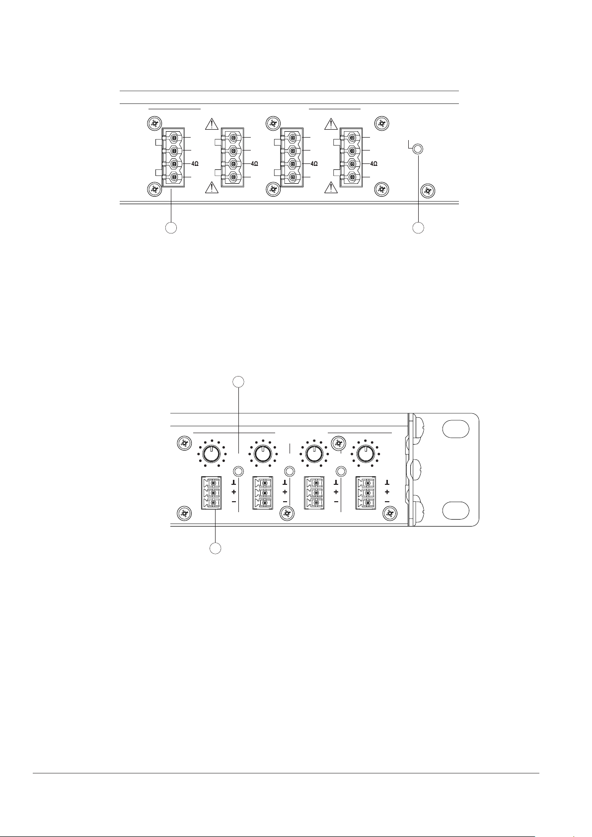
3) Speaker output
SPEAKER OUTPUT
CH 4 CH 3 CH 2 CH 1
100V
70V
100V
70V
100V
70V
100V
70V
Auto
Standby
COM
A
COM
A) Loudspeaker output connections:
The loudspeaker output connections are performed using
4-pin terminal block connectors, making it possible to connect
high and low impedance loudspeakers to the amplier
outputs. Selection can be made between low impedance
(4Ω) or constant voltage (100V / 70V) depending on project
requirements. More information about loudspeaker output
connections is described in the ‘connecting the system’
chapter.
4) Input
B
LINK
4/3
COM
COM
B
B) Auto standby switch:
The amplier has an automatic standby function. The amplier
switches automatically to standby mode when no input signal
is available for 30 minutes. If desired, the automatic standby
mode can be disabled via this switch. The standby function
is by default activated.
INPUT
LINK
3/2
Input adj.Input adj.Input adj.I .
LINK
2/1
Input adj
A
A) Input connections:
Balanced mono sources can be connected to the
3.81mm Terminal block input. A gain control potentiometer
adjusts the sensitivity within a range of 0 dB ~ 50 dB which
allows connection for both microphone or line-level audio
sources.
CH 1CH 2CH 3CH 4
B) Linking switch :
Different input channels can be linked together. Pushing the
button between two channels will link them to each other. This
function eliminates the need to connect inputs with cables.
By pushing the buttons sequentially, multiple channels can
be linked together.
audac.euCEP series
Page 3
Connecting the system:
ATTENTION:
Make sure the power of the device is turned OFF before
any connections or wiring adjustments are made.
Disregarding this rule can lead to permanent damage of
the equipment.
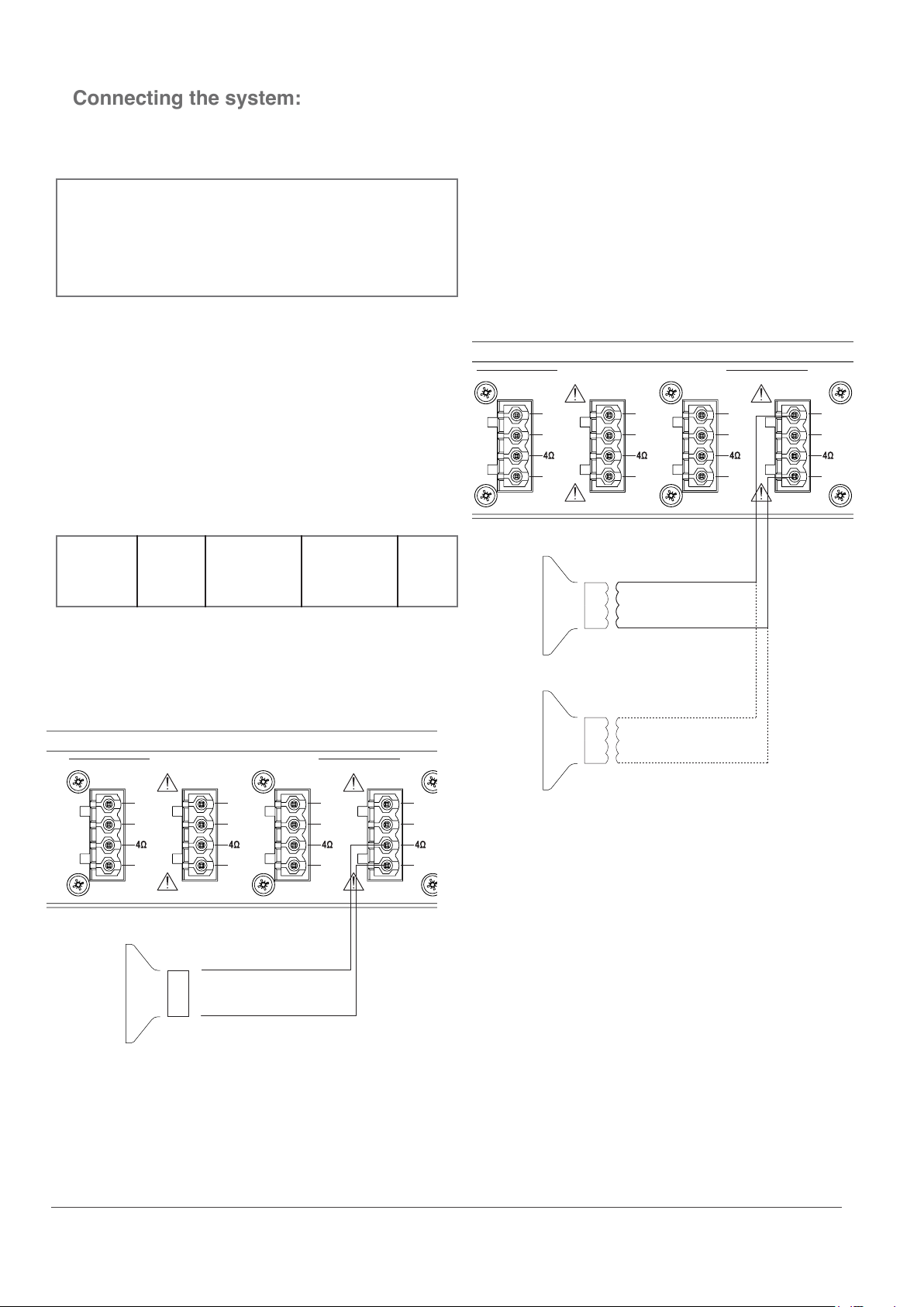
The loudspeakers should be connected to the 4-pin terminal
block connectors on the rear panel of the amplier. Selection
can be made between low impedance (4Ω) or constant
voltage (100V / 70V) depending on project requirements.
The corresponding terminals and settings shall be chosen
depending of the loudspeakers and installation type.
For operating using constant voltage (100V / 70V) audio
distribution systems, all speakers shall be connected in
parallel on the corresponding output terminals, non exceeding
the maximum wattage / minimum impedance of the amplier
SPEAKER OUTPUT
CH 4 CH 3 CH 2 CH 1
100V
70V
100V
70V
100V
70V
100V
70V
Auto
Standby
The table below shows the output voltage, impedance and
maximum power load per channel for each amplier model.
CEP408 4 Ω 62,5Ω/70V 125Ω/100V
CEP803 4 Ω 30W
167Ω/70V 333Ω/100V
80W
For operation in low impedance (4 ohm) mode, any
loudspeaker (or combination) with an impedance higher or
equal to 4Ω can be connected.
SPEAKER OUTPUT
CH 4 CH 3 CH 2 CH 1
100V
70V
COM
100V
70V
COM
100V
70V
COM
100V
70V
COM
COM
COM
COM
+
-
Matching
transformer
+
-
Matching
Auto
Standby
transformer
Depending on the chosen connection method (low
impedance or constant voltage), the output conguration
setup shall be congured accordingly.
COM
+
4Ω
-
Do not connect high and low impedance speakers to one
output at the same time.
audac.euCEP series
Page 4
CAUTION - SERVICING:
EC DECLARATION OF CONFORMITY
This product contains no user serviceable parts. Refer
all servicing to qualied service personnel. Do not
perform any servicing (unless you are qualied to).
ENERGY STAR
This product qualies for ENERGY STAR in the “factory
default” setting and this is the setting in which power
savings will be achieved. Changing the factory default
settings or enabling other features will increase power
consumption that could exceed the limits necessary to
qualify for ENERGY STAR rating. We want to help you
save energy.
WASTE ELECTRICAL AND ELECTRONIC
EQUIPMENT (WEEE)
The WEEE marking indicates that this product should
not be disposed with regular household waste at the
end of its life cycle. This regulation is created to prevent
any possible harm to the environment or human health.
This product is developed and manufactured with
high quality materials and components which can be
recycled and/or reused. Please dispose this product
at your local collection point or recycling centre for
electrical and electronic waste. This will make sure that
it will be recycled on an environmentally friendly manner,
and will help to protect the environment in which we all
live.
This product conforms to all the essential requirements
and further relevant specications described in following
directives: 2014/30/EU (EMC) and 2014/35/ EU (LVD)
CAUTION:
ALWAYS KEEP THESE INSTRUCTIONS. NEVER THROW
THEM AWAY
ALWAYS HANDLE THIS UNIT WITH CARE
HEED ALL WARNINGS
FOLLOW ALL INSTRUCTIONS
NEVER EXPOSE THIS EQUIPMENT TO RAIN,
MOISTURE, ANY DRIPPING OR SPLASHING LIQUID. AND
NEVER PLACE AN OBJECT FILLED WITH LIQUID ON TOP OF
THIS DEVICE
NO NAKED FLAME SOURCES, SUCH AS LIGHTED
CANDLES, SHOULD BE PLACED ON THE APPARATUS
DO NOT PLACE THIS UNIT IN AN ENCLOSED
ENVIRONMENT SUCH AS A BOOKSHELF OR CLOSET.
ENSURE THERE IS ADEQUATE VENTILATION (5 CM) TO
COOL THE UNIT. DO NOT BLOCK THE VENTILATION
OPENINGS.
DO NOT STICK ANY OBJECTS THROUGH THE
VENTILATION OPENINGS.
DO NOT INSTALL THIS UNIT NEAR ANY HEAT SOURCES
SUCH AS RADIATORS OR OTHER APPARATUS THAT
PRODUCE HEAT.
CAUTION
The symbols shown are internationally recognized
symbols that warn about potential hazards of electrical
products. The lightning ash with arrow point in
an equilateral triangle means that the unit contains
dangerous voltages. The exclamation point in an
equilateral triangle indicates that it is necessary for the
user to refer to the users manual.
These symbols warn that there are no user serviceable
parts inside the unit. Do not open the unit. Do not
attempt to service the unit yourself. Refer all servicing to
qualied personnel. Opening the chassis for any reason
will void the manufacturer’s warranty. Do not get the unit
wet. If liquid is spilled on the unit, shut it off immediately
and take it to a dealer for service.Disconnect the unit
during storms to prevent damage.
DO NOT PLACE THIS UNIT IN ENVIRONMENTS WHICH
CONTAIN HIGH LEVELS OF DUST, HEAT, MOISTURE OR
VIBRATION
THIS UNIT IS DEVELOPED FOR INDOOR USE ONLY. DO NOT
USE IT OUTDOORS
PLACE THE UNIT ON A STABLE BASE OR MOUNT IT IN A
STABLE RACK
ONLY USE ATTACHMENTS & ACCESSORIES
SPECIFIED BY THE MANUFACTURER
UNPLUG THIS APPARATUS DURING LIGHTNING
STORMS OR WHEN UNUSED FOR LONG PERIODS OF TIME
ONLY CONNECT THIS UNIT TO A MAINS SOCKET
OUTLET WITH PROTECTIVE EARTHING CONNECTION
THE MAINS PLUG OR APPLIANCE COUPLER IS USED AS
THE DISCONNECT DEVICE, SO THE DISCONNECT DEVICE
SHALL BE READILY OPERABLE
USE THE APPARATUS ONLY IN MODERATE CLIMATES
audac.euCEP series
 Loading...