

Page 1

CELO2
User & Installation
Manual
www.audac.eu
Page 2

2
Page 3

3
Introduction
2” High-end slim ceiling speaker
The CELO2 is the 2” version of AUDAC’s CELO High-end slim ceiling speaker series
with an RMS power of 10 Watt and Maximum power of 20 Watt, consisting of a 2” full
range aluminum cone driver.
Due to its slim grill design with very thin border of only 1 mm and a limited grill depth
which extrudes from the ceiling surface by only 3.2 mm, these speakers will become
nearly invisible when mounted. To make them blend in even more, they can be painted
in the same colour as the surrounding surface. This elegant and unobtrusive grill is held
in place by means of powerful neodymium magnets, making assembly and disassembly
very simple, but still reliable enough for keeping the grill in place during the complete
lifetime of the loudspeaker.
The 2” full range aluminum cone driver is protected against overload through an integrated
self-resetting protection circuit. All these details share their part to the quality of the
Mero 2, resulting in an highly reliable loudspeaker producing a pure sound with an RMS
power of 10 Watt.
An elegant look with minimal visual impact is created by the slim grill with a very thin
border, while great ease and installers convenience is guaranteed using the quick-fix
mechanism with Gold-CON connectors. The grill is held in place using neodymium
magnets, providing a quick and stable assembly.
Page 4
4
Precautions
READ FOLLOWING INSTRUCTIONS FOR YOUR OWN SAFETY
• ALWAYS KEEP THESE INSTRUCTIONS FOR FUTURE REFERENCE. NEVER
THROW THEM AWAY
• ALWAYS HANDLE THIS UNIT WITH CARE
• CLEAN ONLY WITH DRY CLOTH
• HEED ALL WARNINGS AND FOLLOW ALL INSTRUCTIONS
• NEVER EXPOSE THIS EQUIPMENT TO RAIN, MOISTURE, ANY DRIPPING OR
SPLASHING LIQUID. AND NEVER PLACE AN OBJECT FILLED WITH LIQUID ON
TOP OF THIS DEVICE
• DO NOT INSTALL THIS UNIT NEAR ANY HEAT SOURCES SUCH AS RADIATORS
OR OTHER APPARATUS THAT PRODUCE HEAT
• DO NOT PLACE THIS UNIT IN ENVIRONMENTS WITH A HIGH LEVEL OF DUST,
HEAT, MOISTURE OR VIBRATION
• THIS UNIT IS DEVELOPED FOR INDOOR USE ONLY. DO NOT USE IT OUTDOORS
• ONLY USE ATTACHMENTS & ACCESSORIES SPECIFIED BY THE
MANUFACTURER.
• ONLY INSTALL THE SPEAKER IN LOCATIONS THAT CAN STRUCTURALLY
SUPPORT THE WEIGHT OF THE SPEAKER. IGNORING THIS CAN BRING THE
SPEAKER DOWN.
• DO NOT USE ANY OTHER METHOD THAN SPECIFIED TO MOUNT THE
SPEAKER. IF EXTREME FORCE IS APPLIED TO THE SPEAKER, IT COULD FALL
DOWN
• CAREFULLY CHECK THE UNIT’S CONDITION AFTER UNPACKING.
IF THERE IS ANY DAMAGE TO THE CARTON BOX OR THE UNIT ITSELF,
INFORM YOUR VENDOR IMMEDIATELY.
Page 5
5
CAUTION
• USE CABLES OF THE RIGHT GAUGE TO CONNECT THE LOUDSPEAKER
• USE CABLES WITH CLEAR COLOUR CODING INDICATING THE POLARITY AND
MAINTAIN THE SAME POLARITY THROUGHOUT THE WHOLE SYSTEM.
• ONLY USE THE CORRECT AMPLIFIER OUTPUT VOLTAGE AND IMPEDANCE.
EXCEEDING THESE LIMITS COULD CAUSE FIRE OR OTHER FAILURES.
AVOID EXPLOSIONS: DO NOT USE THE SPEAKER AROUND GASOLINE,
THINNER OR OTHER COMBUSTIBLES
• AVOID ELECTRIC SHOCKS: SWITCH OFF THE AMPLIFIER WHEN CONNECTING
THE LOUDSPEAKER
• DO NOT USE THE LOUDSPEAKER FOR AN EXTENDED PERIOD OF TIME AT
DISTORTED SOUND. THIS COULD CAUSE PERMANENT DAMAGE.
CAUTION - SERVICING
This product contains no user serviceable parts. Refer all servicing
to qualified service personnel. Do not perform any servicing
(unless you are qualified to do so.)
EC DECLARATION OF CONFORMITY
This product conforms to all the essential requirements and
further relevant specifications described in following directives:
2004/108/EC (EMC) and 2006/95/EC (LVD)
WASTE ELECTRICAL AND ELECTRONIC EQUIPMENT (WEEE)
The WEEE marking indicates that this product should not be
disposed with regular houshold waste at the end of its product
life. This regulation is created to protect both the environment
and human health.
This product is developed and manufactured with high quality
materials and components which can be recycled and/or reused.
Please dispose this product to your local collection point or
recycling centre for electrical and electronic waste. This will
make to sure that it will be recycled on an environmentally friendly
manner, and will help to protect the environment in which we all
live.
Page 6
6
Installing the CELO
Introduction
The CELO speakers feature a quick-fixing mechanism, which allows quick and easy
installation of the loudspeakers in only a few minutes.
The installation of the CELO speakers requires a minimum amount of installation skills.
Before the loudspeaker is installed, the location whereto it will be mounted should be
carefully checked to make sure the surface can support the weight of the speaker and
no lines for water, gas, electricity or other supplies are crossing this point.
Installation procedure
To ensure a safe and secure mounting of the loudspeaker, the installation should be
done according to the procedure described below:
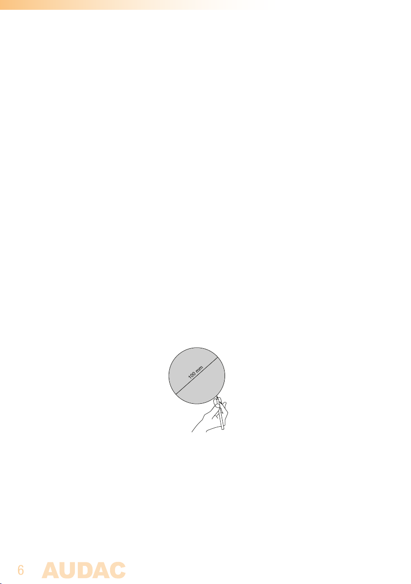
1) Firstly cut a hole into the surface whereto the loudspeaker should be installed with
a diameter of 100 mm. The included cutout template can be used for an easy marking
of the installation hole.
2) Provide the loudspeaker connection cable through the mounting hole. Make sure
the used connection cable is sufficiently thick. The required cable thickness depends
on its length.
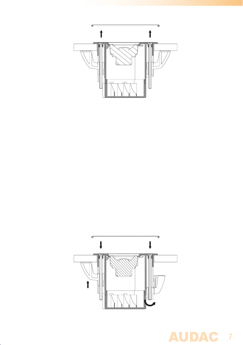
3) Take the loudspeaker, and remove the front grill which is held in place by
neodymium magnets. The front grill can be easily removed by gently pulling it.
Page 7
7
4) Connect the loudspeaker connection cable to the gold plated spring clamp
connectors. Press the button of the corresponding terminal down and insert
the connection cable. After releasing the button, the cable is connected to the
loudspeaker. The Red terminal indicates positive (+) pole and the Black terminal
indicates the negative (-) pole.
Mind the polarity markings when wiring the loudspeaker cables.
Maintain the same polarity and wiring colour coding throughout the entire system to
avoid any mistakes causing malfunction or distortion.
5) Once the connections are made, the loudspeaker can be installed in the provided
mounting hole. Make sure the mounting clips of the loudspeaker are rotated inwards,
making the speaker fit through the hole. Insert the speaker through the provided
mounting hole, and use a screwdriver for tightening the fixing screws.
Once the screws are tightened a quarter turn, the mounting clip will rotate outwards
and will be locked behind the surface. From then on, the loudspeaker is anchored in
the surface and thus can not fall.
6) After the screws are tightened and the speaker is level with the surface, the front
grill can be assembled to the loudspeaker.
Page 8

8
Additional Information
Technical specifications
RMS Power 10 Watt
Max. Power 20 Watt
Nominal impedance 8 Ohm
Sensitivity (1W / 1m) 83 dB
Sound pressure (Max W / 1m) 93 dB
Frequency response (±3 dB) 120 Hz - 20 kHz
Drivers 2” Aluminium full range
Connectors Gold plated spring clamps
Mounting 2-Screw quick-fixing mechanism
Construction High-Quality ABS
Front finish White Thin edge grill (RAL9003)
(1 mm width x 3.2 mm height edge)
Dimensions Ø 118 x 98 mm
Cut-out measurement Ø 100 mm
Built-in depth 94 mm
Weight 0.325 Kg
Packaging Carton box
Shipping weight & Volume 0.47 Kg - 0,0026 Cbm
Accessories included Cut-out template
Instruction manual
 Loading...