

Page 1

CAP Series
User Manual
www.audac.eu
Page 2

2
Page 3

3
Index
Introduction 5
CAP Series Block Diagram 6
Precautions 7
Safety requirements 7
Caution servicing 7
EC Declaration of Conformity 7
Waste of Electrical and Electronic Equipment (WEEE) 8
Caution 8
Chapter 1: Pin connections and connectors 9
Connection standards 9
Wire up the system 9
Chapter 2: Front & rear panel 10
Front panel overview 10
Front panel description 10
Rear panel overview 11
Rear panel description 11
Chapter 3: Connecting the Amplifier 12
Input connections 12
Output connections 12
Chapter 4: Additional information 14
Technical specifications 14
Notes 16
Page 4

4
Page 5
5
Introduction
Multi Channel 100V Power Amplifiers
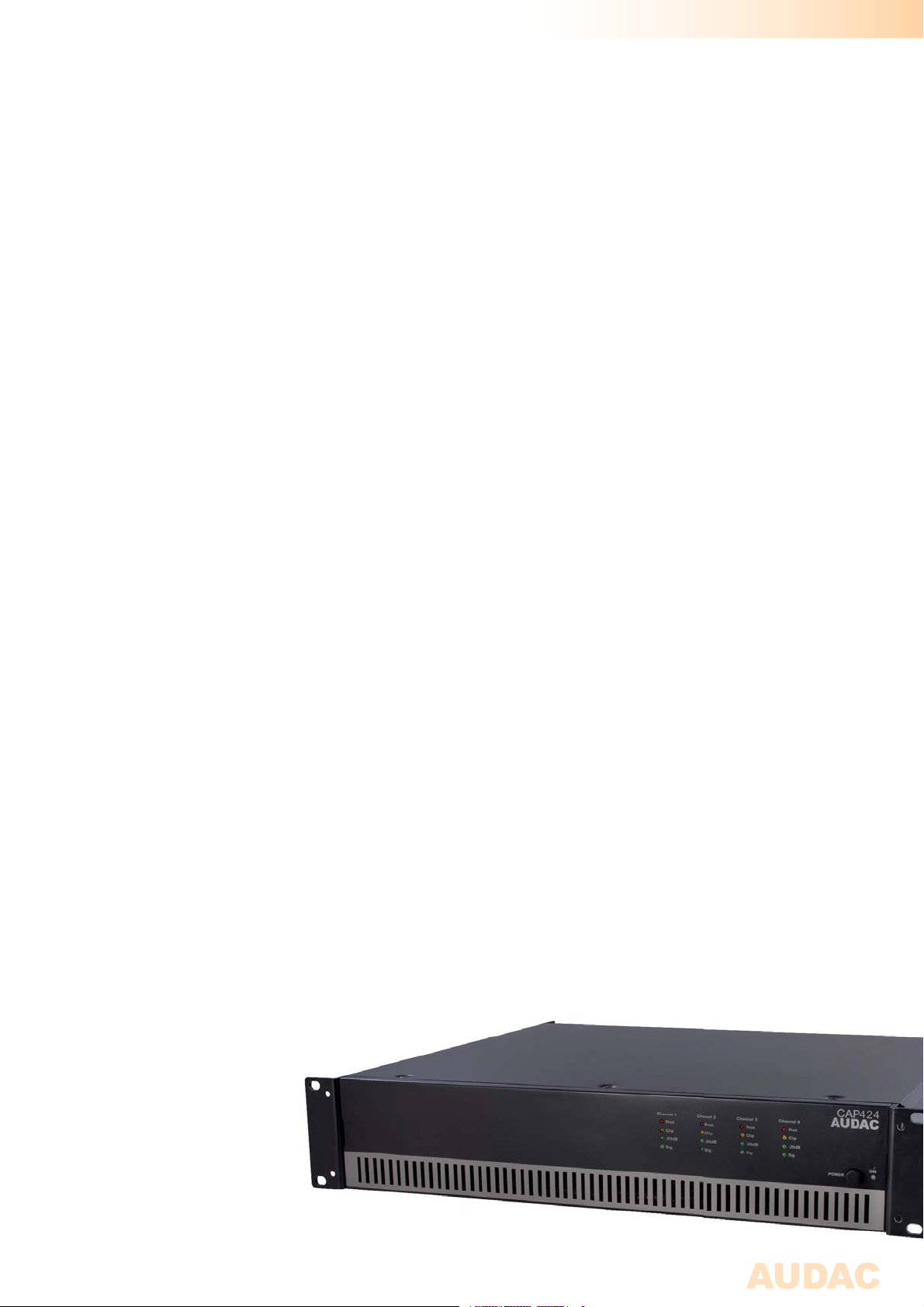
The CAP Series are professional 100V Multi-Channel Power Amplifiers, containing various
models with different channels and different output power configuration. Different output
configurations with two and four channels and power ratings for 240 Watt and 480 Watt for
each channel are available.
This way, a flexible solution is created for Multi-Zone audio distribution systems with two
or more independent zones.
They are designed as no-nonsense amplifiers with only the necessary controls and
connections, which creates great simplicity in use and installation. A high efficiency and
reliability of the devices is achieved by using switching power supplies in combination with
Class-D Amplifier technology. A temperature controlled fan constantly keeps all parts within
the right operation range, while avoiding excessive buzz. A built-in multipurpose protection
circuit protects against DC malfunction, Short circuit, overheating, overload and limits the
signal when necessary.
The input connections are performed using balanced XLR connectors and Link output
connectors are provided for link through to other amplifiers. Besides, a high-pass filter
switch (400 Hz) and a Gain adjustment potentiometer are provided for each channel.
The output connections are performed using reliable terminal block connectors and this all
is housed into a solid constructed, double rack space (2 HE) 19” rack mounting housing.
Page 6
6
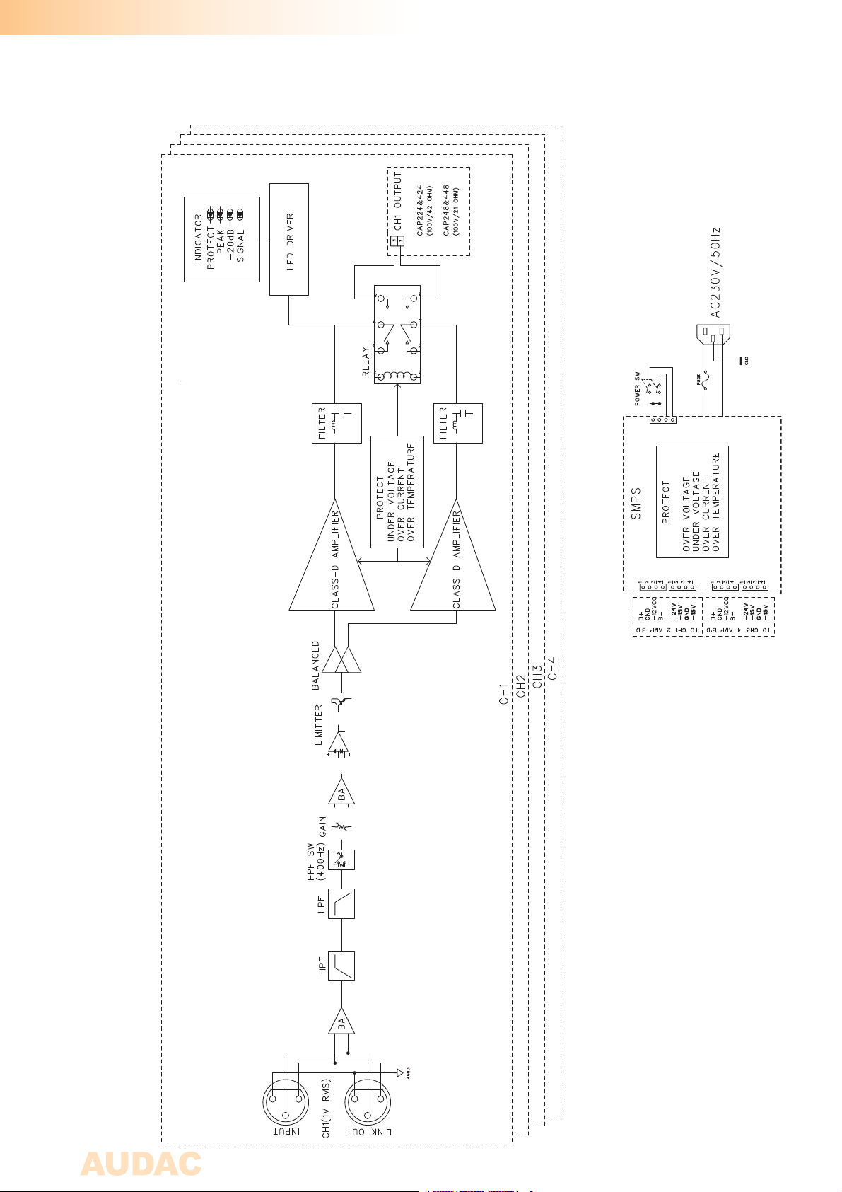
CAP Series Block Diagram
Page 7
7
Precautions
READ FOLLOWING INSTRUCTIONS FOR YOUR OWN SAFETY
ALWAYS KEEP THESE INSTRUCTIONS. NEVER THROW THEM AWAY
ALWAYS HANDLE THIS UNIT WITH CARE
HEED ALL WARNINGS
FOLLOW ALL INSTRUCTIONS
NEVER EXPOSE THIS EQUIPMENT TO RAIN, MOISTURE, ANY DRIPPING OR SPLASHING
LIQUID. AND NEVER PLACE AN OBJECT FILLED WITH LIQUID ON TOP OF THIS DEVICE.
DO NOT PLACE THIS UNIT IN AN ENCLOSED ENVIRONMENT SUCH AS A BOOKSHELF
OR CLOSET. ENSURE THERE IS ADEQUATE VENTILATION TO COOL THE UNIT. DO NOT
BLOCK THE VENTILATION OPENINGS.
DO NOT STICK ANY OBJECTS THROUGH THE VENTILATION OPENINGS.
DO NOT INSTALL THIS UNIT NEAR ANY HEAT SOURCES SUCH AS RADIATORS OR
OTHER APPARATUS THAT PRODUCE HEAT
DO NOT PLACE THIS UNIT IN ENVIRONMENTS WHICH CONTAIN HIGH LEVELS OF DUST,
HEAT, MOISTURE OR VIBRATION
THIS UNIT IS DEVELOPED FOR INDOOR USE ONLY. DO NOT USE IT OUTDOORS
PLACE THE UNIT ON A STABLE BASE OR MOUNT IT IN A STABLE RACK
ONLY USE ATTACHMENTS & ACCESSORIES SPECIFIED BY THE MANUFACTURER
UNPLUG THIS APPARATUS DURING LIGHTNING STORMS OR WHEN UNUSED FOR LONG
PERIODS OF TIME
ONLY CONNECT THIS UNIT TO A MAINS SOCKET OUTLET WITH PROTECTIVE
EARTHING CONNECTION
CAUTION - SERVICING
This product contains no user serviceable parts. Refer all servicing to
qualified service personnel. Do not perform any servicing (unless you
are qualified to)
EC DECLARATION OF CONFORMITY
This product conforms to all the essential requirements and further
relevant specifications described in following directives: 2004/108/EC
(EMC) and 2006/95/EC (LVD)
Page 8
8
WASTE ELECTRICAL AND ELECTRONIC EQUIPMENT (WEEE)
The WEEE marking indicates that this product should not be disposed
with regular houshold waste at the end of its working life. This regulation
is created to prevent any possible harm to the environment or human
health.
This product is developed and manufactured with high quality materials
and components which can be recycled and/or reused. Please dispose
this product to your local collection point or recycling centre for electrical
and electronic waste. This will make to sure that it will be recycled
on an environmentally friendly manner, and will help to protect the
environment in which we all live.
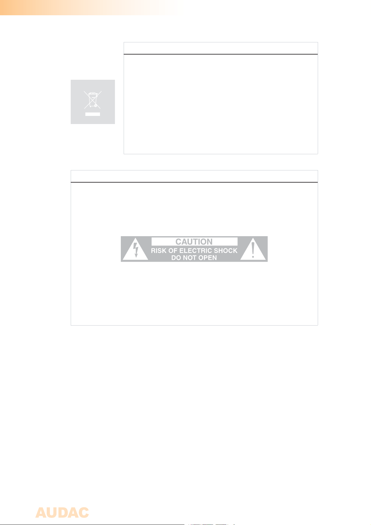
CAUTION
The symbols shown are internationally recognized symbols that warn about potentional
hazards of electrical products. The lightning flash with arrowpoint in an equilateral
triangle means that the unit contains dangerous voltages. The exclamation point in
an equilateral triangle indicates that it is necessary for the user to refer to the users
manual.
These symbols warn that there are no user serviceable parts inside the unit. Do not
open the unit. Do not attempt to service the unit yourself. Refer all servicing to qualified
personnel. Opening the chassis for any reason will void the manufacturer’s warranty. Do
not get the unit wet. If liquid is spilled on the unit, shut it off immediately and take it to a
dealer for service. Disconnect the unit during storms to prevent damage.
Page 9
Chapter 1
Pin connections and connectors
CONNECTION STANDARDS
The in- and output connections for AUDAC audio equipment are performed corresponding
to international wiring standards for professional audio equipment.
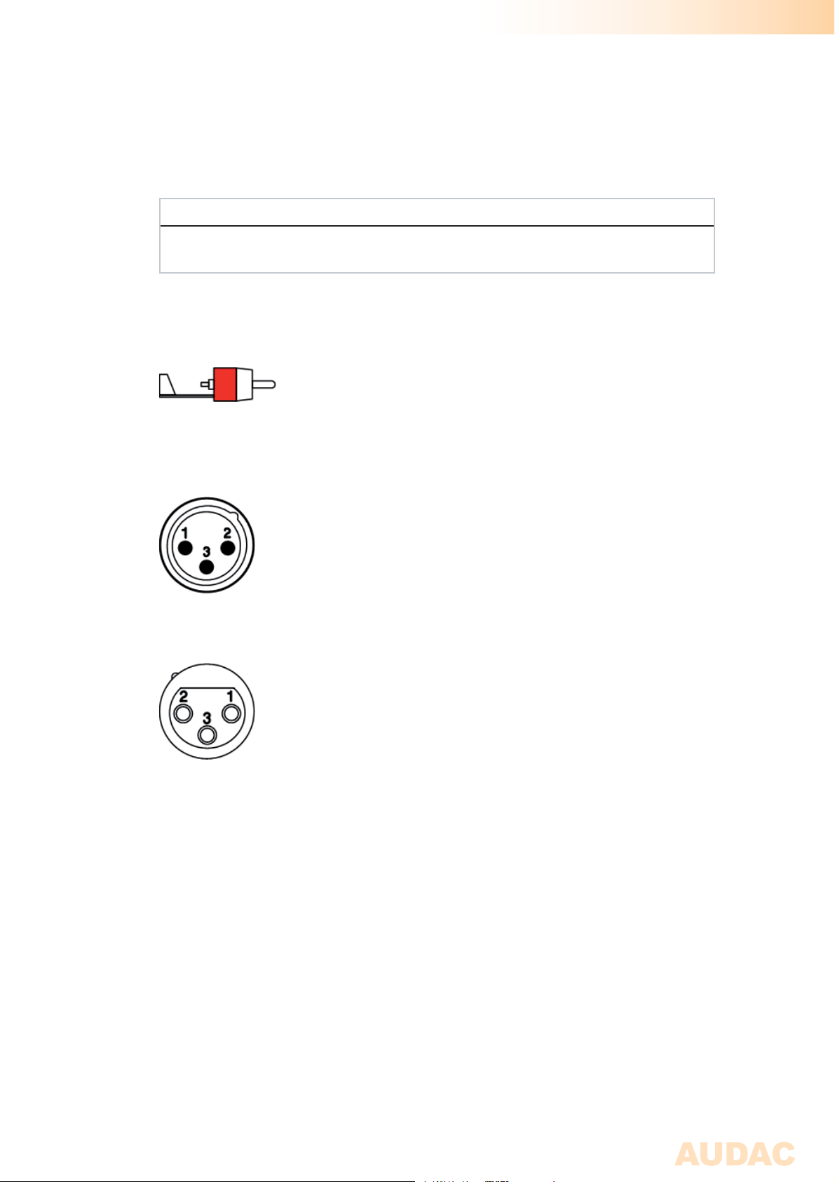
Cinch (RCA):
For unbalanced line input connections
Tip: Signal Sleeve: Ground
White: Left Red: Right
XLR:
For balanced signal input connections
Pin 1: Ground
Pin 2: Signal +
Pin 3: Signal -
For balanced signal link-through connections
Pin 1: Ground
Pin 2: Signal +
Pin 3: Signal -
Wire up the system
The wiring of the system must be done according to the following rules, to guarantee a
proper functioning of the system in all circumstances.
1. Speaker cable for amplified outputs:
Minimum 2 x 1.5 mm²
If distance > 15m: 2 x 2.5 mm²)
2. Music sources and zone outputs:
Must be connected with high-quality audio cable and high-quality
connectors
9
Page 10
Chapter 2
Front & rear panel
Front Panel overview
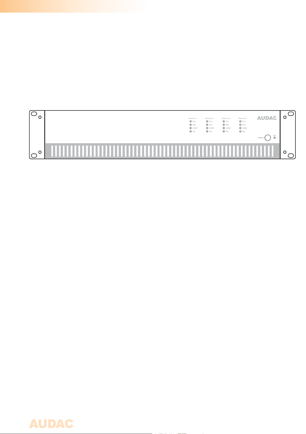
Front panel description
CAP424
The front panel of the CAP series slighly varies depending of the output configuration and
power rating, but basically the panel layout for all CAP amplifiers is similar.
Power switch
A power switch allows to switch the amplifier on and off, while the blue indicator LED
located next to the button illuminates when the power is switched on.
Indicator Led’s
Four LED’s for every channel indicate the operation of the amplifier. The green Signal
LED illuminates whenever a signal is present, while the -20dB LED illuminates when the
input signal exceeds the - 20 dBu level. The Clip LED illuminates when the corresponding
channel is working at maximum level. To ensure the best signal-to-noise ratio, the Clip
LED may only illuminate at peak levels.
When the Clip LED illuminates frequently, the amplifier will be overloaded, a distorted
“Clipping” sound will be available on the output. The Protection LED will illuminate when
overheating occurs, or any other fault is detected. When the protection LED is illuminated,
no signal will be available on the outputs. The protection LED’s will also illuminate for a
few seconds when powering up the amplifier, and when the amplifier is switched off they
will slowly fade out.
Page 11
Rear Panel overview
AC Input
230V 50Hz, 1080W
FUSE T6.3AH/25 0V
CAP424
AUDAC
Rear panel description
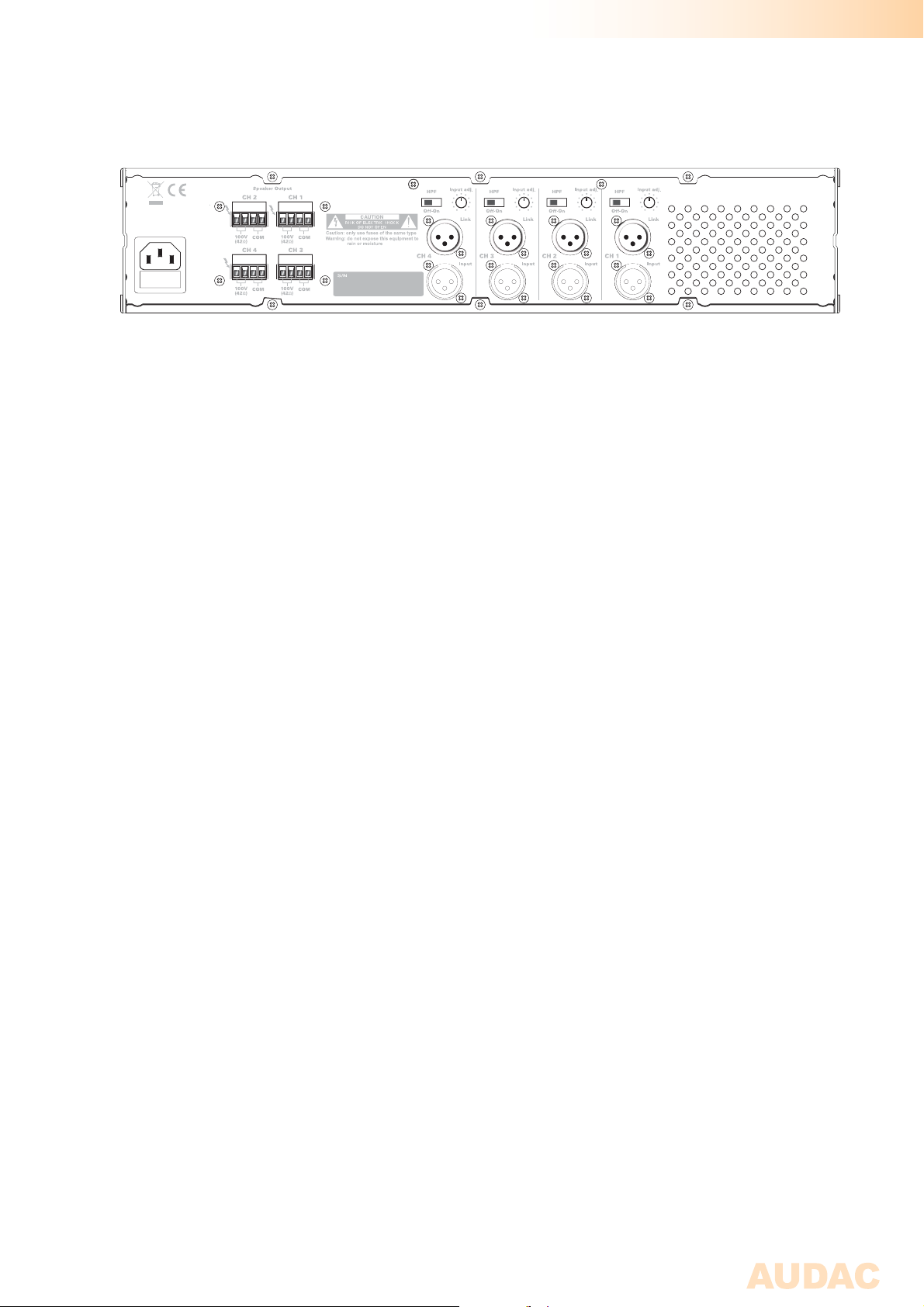
The rear panel of the CAP series slightly varies depending of the output configuration and
power rating, but basically the panel layout for all CAP amplifiers is similar. An XLR input
connector with XLR link-through output connector, a high pass filter switch, a gain control
potentiometer and an terminal block output connector are provided for every channel.
AC Power inlet with fuse
The mains power supply (230~240 V AC / 50 Hz) has to be applied to this AC power
inlet. The connection is made by an IEC power connector and is fitted with a fuse. When
replacing the fuse, make sure that the value of the replacement fuse matches the value of
the original fuse. (CAP224: T4AL/250V - CAP248: T6.3AH/250V - CAP424: T6.3AH/250V
- CAP448: T12AH/250V)
High pass filter switch
By means of this switch, the integrated High Pass Filter (HPF) can be switched ON and
OFF. When the filter is switched ON, frequencies below 400Hz will be suppressed.
This can be useful for eliminating low-frequency hum and noise caused by external
equipment and protects speakers from damage caused by excessive low frequency
transients.
Gain control potentiometer
Each channel is fitted with a gain control knob whereby the level for each individual
channel can be adjusted.
Loudspeaker connections
The loudspeaker output connections are performed using 4-pin terminal block
connectors, making it possible to connect high impedance (100V) loudspeakers to the
amplifier outputs.
Input connections
The input connections of the amplifier are performed using balanced XLR connectors.
Every channel has a XLR input connector and a XLR link output connector. The input
signal from the signal source, pre-amplifier or mixer should be connected to the XLR
input connections. And by means of the XLR link output connectors, the signal can be
linked through to multiple amplifiers.
1
Page 12
Chapter 3
Connecting the Amplifier
NOTE
Make sure the power is swiched OFF when any change is made to the connections of the
amplifier.
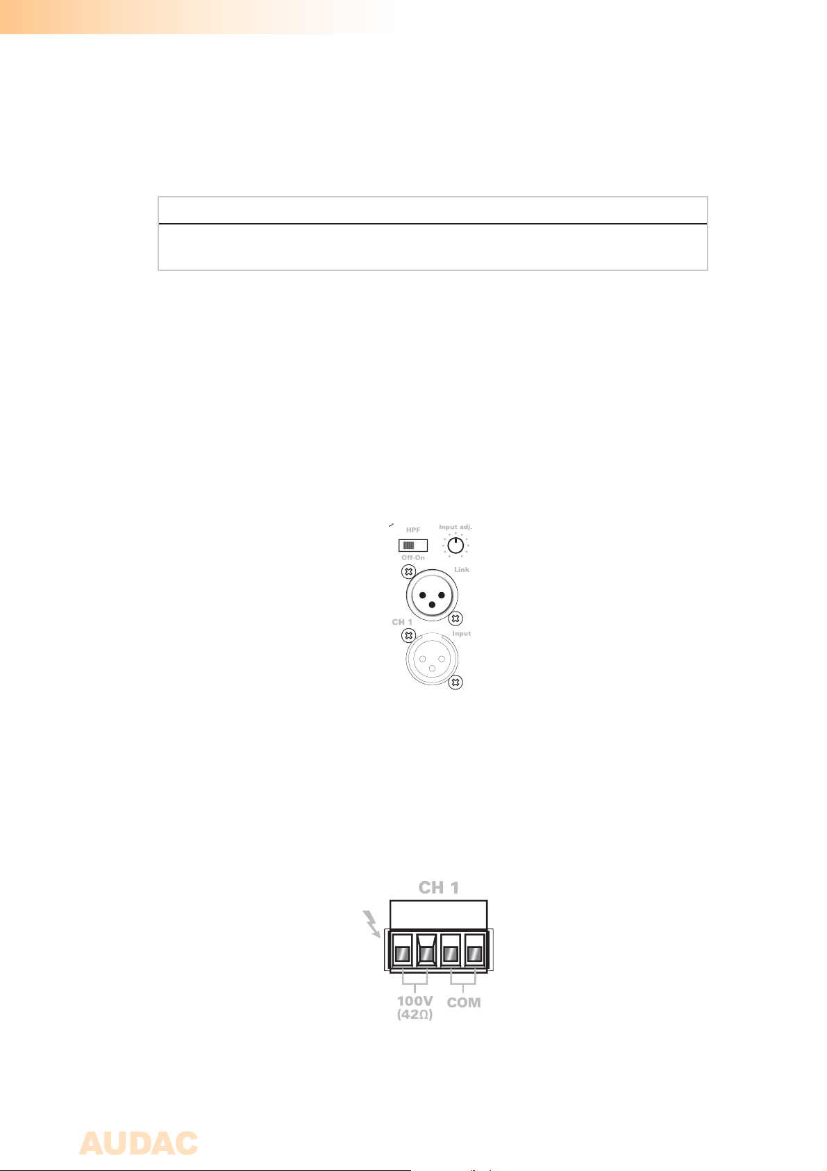
Input connections
The input connections of the amplifier are performed using balanced XLR connectors. Every
channel has a XLR input connector and a XLR link output connector.
The input signal from the signal source, pre-amplifier or mixer should be connected to the
XLR input connections. And by means of the XLR link output connectors, the signal can be
linked through to multiple amplifiers.
Output connections
The loudspeaker output connections are performed using 4-pin terminal block
connectors, making it possible to connect high impedance (100V) loudspeakers to the
amplifier outputs.
Page 13
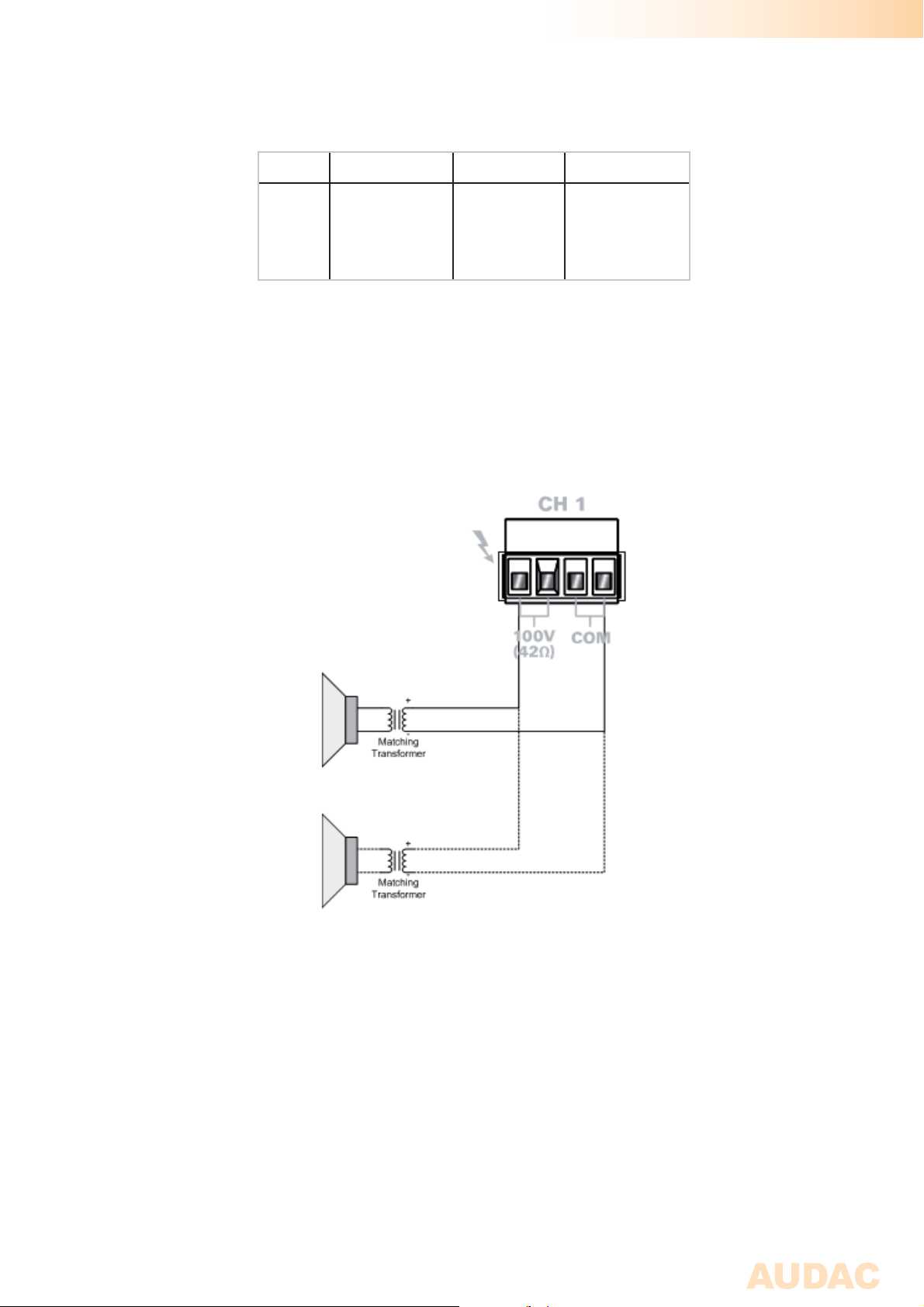
The table below shows the output voltage, impedance and maximum power load for
each corresponding amplifier.
Output Voltage Impedance Power
CAP224
CAP248
CAP424
CAP448
The 100 Volt speakers may be connected in parallel on the outputs of the amplifier
unless the maximum load / impedance has been reached. The number of allowable
loadspeakers depends of the power / impedance of each connected loudspeaker.
100 Volt
100 Volt
100 Volt
100 Volt
42 Ohm
21 Ohm
42 Ohm
21 Ohm
240 Watt
480 Watt
240 Watt
480 Watt
Page 14

Chapter 4
Additional information
Technical specifications
Output Power CAP224 2 x 240 Watt
(1 kHz, THD 1%) CAP248 2 x 480 Watt
CAP424 4 x 240 Watt
CAP448 4 x 480 Watt
Frequency response 50 Hz - 22 kHz
Signal to Noise Ratio > 100 dB
Total Harmonic Distortion + Noise < 0.3%
Common Mode Rejection 70 dB
Crosstalk > 80 dB
Inputs Type Balanced Line
Connectors Female XLR Input
Male XLR Link Output
Impedance 10 k Ohm
Sensitivity 1 V RMS
Output Type 100 V Loudspeaker Output
Connectors 4-pin Euro Terminal Block ~ 5.08 mm
Impedance CAP224/424 42 Ohm
CAP248/448 21 Ohm
Controls Gain
High-Pass filter switch (400 Hz)
Indicators Power
Protect
Peak
-20 dB
Signal
Protection DC-Short Circuit
Over Heating
Over Load
Limiter
Cooling system Temperature controlled fan
Amplifier technology Class-D
Power supply Type Switching mode
Range 230~240 V AC / 50 Hz
4
Page 15

Power consumption Idle CAP224/248 50 Watt
CAP424 /448 89 Watt
1/8 Rated Power CAP224 115 Watt
CAP248 187 Watt
CAP424 218 Watt
CAP448 440 Watt
1/3 Rated Power CAP224 221 Watt
CAP248 400 Watt
CAP424 435 Watt
CAP448 870 Watt
Weight CAP224 7.2 Kg
CAP248 7.5 Kg
CAP424 8.35 Kg
CAP448 8.85 Kg
Page 16

Notes
 Loading...