

Page 1

APT20
User Manual
www.audac.eu
Page 2

2
Page 3

3
Index
Introduction 5
Precautions 6
Safety requirements 6
Caution servicing 6
EC Declaration of conformity 7
Waste of Electrical and Electronic Equipment (WEEE) 7
Caution 7
Chapter 1: Pin connections & connectors 8
Chapter 2: Overview APT20 9
Front panel 9
Rear panel 10
Chapter 3: APT20 Quick start guide 11
Chapter 4: Additional information 12
Technical specifications 12
Page 4

4
Page 5

5
Introduction
Two channel phantom power supply
The APT20 is phantom power supply unit containing two independant working channels
for use with two condenser microphones. It supplies 48V DC to the microphones and
routes the signal to a mixer or microphone amplifier.
The connections are performed by using XLR connectors for the in- and outputs and
at the back is an IEC power connector with power switch provided for connecting the
APT20 to the mains network.
Page 6

6
Precautions
READ FOLLOWING INSTRUCTIONS FOR YOUR OWN SAFETY
ALWAYS KEEP THESE INSTRUCTIONS. NEVER THROW THEM AWAY
ALWAYS HANDLE THIS UNIT WITH CARE
HEED ALL WARNINGS
FOLLOW ALL INSTRUCTIONS
NEVER EXPOSE THIS EQUIPMENT TO RAIN, MOISTURE, ANY DRIPPING OR
SPLASHING LIQUID. AND NEVER PLACE AN OBJECT FILLED WITH LIQUID ON TOP
OF THIS DEVICE.
DO NOT INSTALL THIS UNIT NEAR ANY HEAT SOURCES SUCH AS RADIATORS OR
OTHER APPARATUS THAT PRODUCE HEAT
DO NOT PLACE THIS UNIT IN ENVIRONMENTS WHICH CONTAIN HIGH LEVELS OF
DUST, HEAT, MOISTURE OR VIBRATION
THIS UNIT IS DEVELOPED FOR INDOOR USE ONLY. DO NOT USE IT OUTDOORS
PLACE THE UNIT ON A STABLE BASE OR MOUNT IT IN A STABLE RACK
ONLY USE ATTACHMENTS & ACCESSORIES SPECIFIED BY THE MANUFACTURER
UNPLUG THIS APPARATUS DURING LIGHTNING STORMS OF WHEN UNUSED FOR
LONG PERIODS OF TIME
ONLY CONNECT THIS UNIT TO A MAINS SOCKET OUTLET WITH PROTECTIVE
EARTHING CONNECTION
CAUTION - SERVICING
This product contains no user serviceable parts. Refer all servicing
to qualified service personnel. Do not perform any servicing
(unless you are qualified to do so.)
Page 7
7
CAUTION
The symbols shown are internationally accepted symbols that warn of potentional
hazards of electrical products. The lightning flash with arrowpoint in an equilateral
triangle means that there are dangerous voltages present within the unit. The
exclamation point in an equilateral triangle indicates that it is necessary for the user
to refer to the users manual.
These symbols warn that there are no user serviceable parts inside the unit. Do
not open the unit. Do not attempt to service the unit yourself. Refer all servicing to
qualified personnel. Opening the chassis for any reason will void the manufacturers
warranty. Do not get the unit wet. If liquid is spilled on the unit, shut it off
immediately and take it to a dealer for service. Disconnect the unit during storms to
prevent damage.
EC DECLARATION OF CONFORMITY
This product conforms to all the essential requirements and
further relevant specifications described in following directives:
2004/108/EC (EMC) and 2006/95/EC (LVD)
WASTE ELECTRICAL AND ELECTRONIC EQUIPMENT (WEEE)
The WEEE marking indicates that this product should not be
disposed with regular houshold waste at the end of its working
life. This regulation is created to prevent any possible harm to the
environment or human health.
This product is developed and manufactured with high quality
materials and components which can be recycled and/or reused.
Please dispose this product to your local collection point or
recycling centre for electrical and electronic waste. This will make
to sure that it will be recycled on an environmentally friendly
manner, and will help to protect the environment in which we
all live.
Page 8

8
Chapter 1
Pin connections and connectors
CONNECTION STANDARDS
The in- and output connections for AUDAC audio equipment are performed
corresponding to international wiring standards for professional audio equipment.
XLR:
For balanced microphone input connections
Pin 1: Ground
Pin 2: Signal +
Pin 3: Signal -
Pin 1: Ground
Pin 2: Signal +
Pin 3: Signal -
Page 9
9
Chapter 2
Overview APT20
Front panel
IN OUT IN OUT
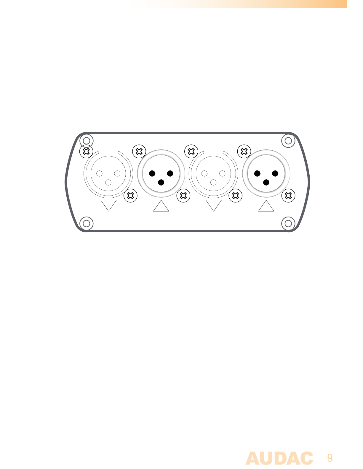
The front panel of the APT20 contains all connections for connecting two condenser
microphones and routing their signal to a mixer or microphone amplifier
1) XLR input connectors:
The condenser microphones should be connected to the input XLR connectors. The
input XLR connectors are 3-pin Female XLR connectors
2) XLR output connectors:
The microphones output signals will be available at these output XLR connectors.
These outputs should be connected to the mixer or microphone pre-amplifier. The
output XLR connectors are 3-pin male XLR connectors.
Page 10
10
Rear panel
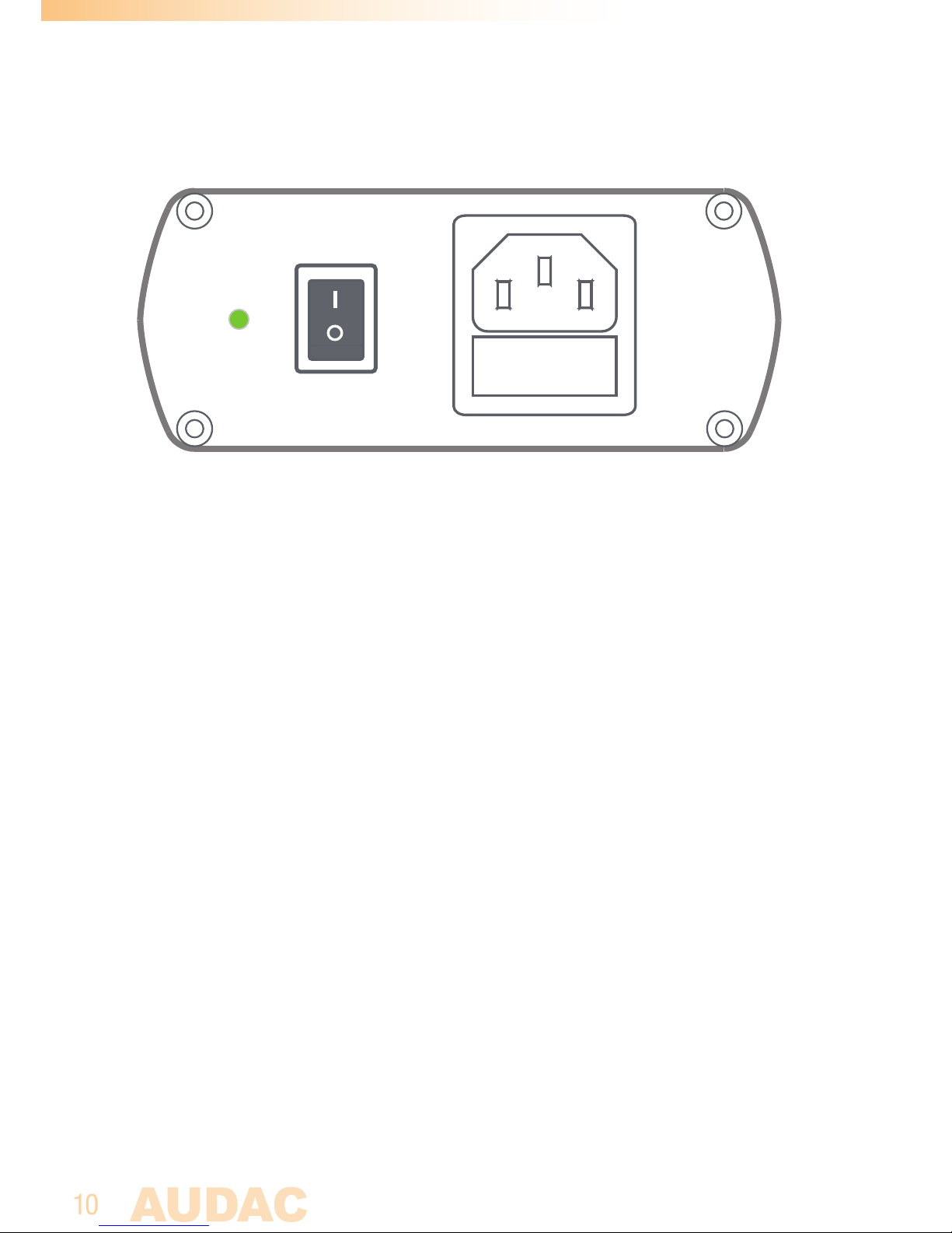
The rear panel of the APT20 contains the power switch, mains power inlet and power
indication LED.
1) Power switch:
By toggling this switch, the power for the APT20 can be switched ON and OFF.
The power LED will illuminate when the power is switched ON.
2) IEC Mains power inlet:
The mains power supply (230V AC / 50Hz) has to be applied to this AC power inlet.
The connection is made by an IEC power connector and is fitted with a fuse. When
replacing the fuse, make sure that the value of the replacement fuse matches the
value of the original fuse. (T0.5A/250V)
Power
230V~/50Hz
Fuse: T 0.5A / 250V
Page 11
11
Chapter 3
APT20 Quick start guide
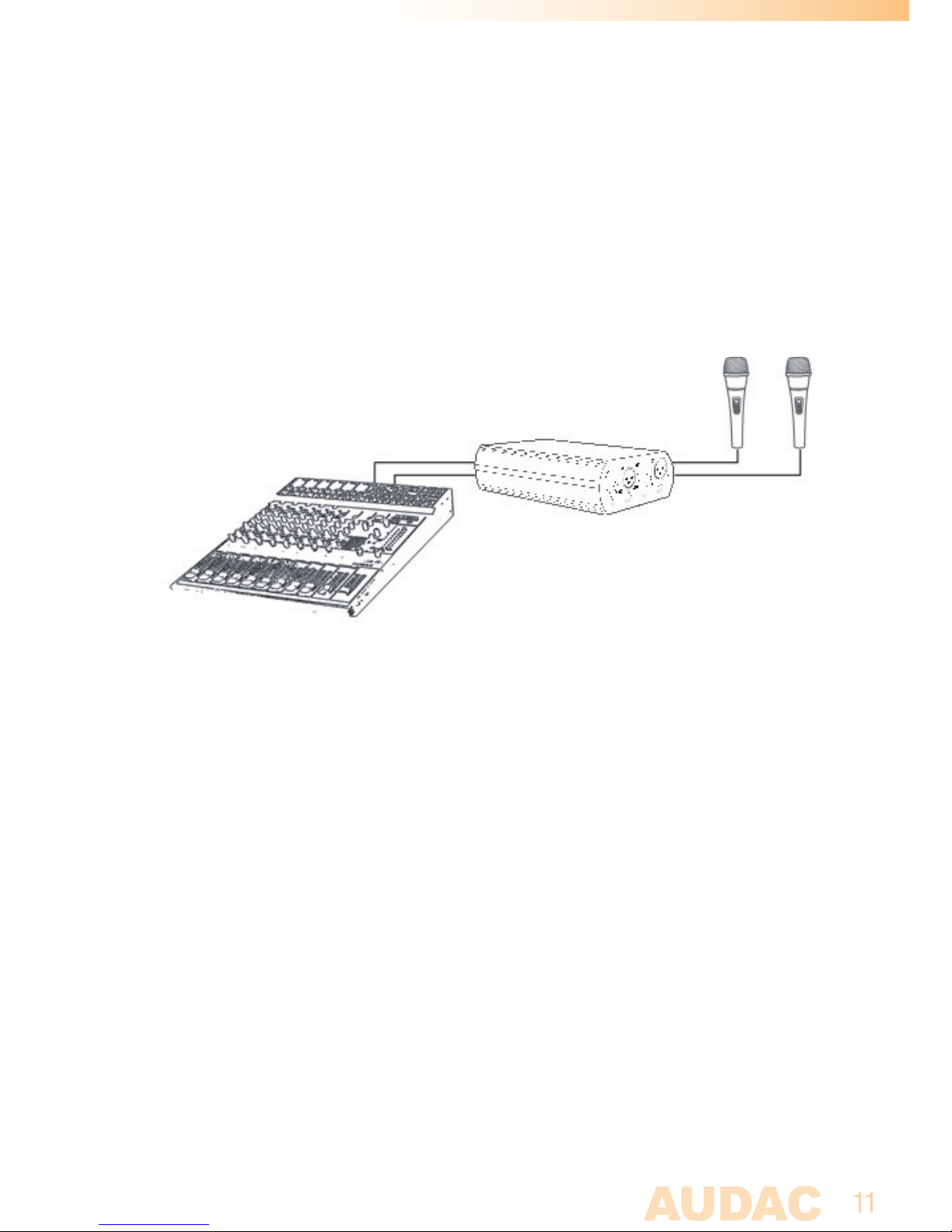
This chapter guides you through the setup process of a basic project with one APT20
phantom power supply, two condenser microphones and a mixer or microphone amplifier.
Overview of the APT20 setup
1) Connecting the APT20
Connect the condenser microphones to the Female XLR input connectors on
the APT20, and connect your mixer or microphone amplifier to Male XLR output
connectors. Connect the APT20 by using an IEC power lead to the mains network.
2) Turn the device ON
Turn the device on by toggeling the power switch to the “I” position.
The power indication LED will illuminate in Green when the device is powered up.
3) Ready
48 Volts phantom power is now delivered to your condenser microphones and the
signal coming from the microphones is available on the Male XLR output connectors.
Your system is now working properly and ready for use.
Page 12

12
Chapter 4
Additional information
Technical specifications
Peripheral
Inputs 2 x Microphone input
Outputs 2 x Microphone output
Connectors
Microphone input 3-Pin Female XLR
Microphone output 3-Pin Male XLR
Power IEC Mains connector with fuse
(Fuse type: T0.5A/250V)
Specifications
Phantom power 48 Volt
THD+N < 0.0005 %
Signal / Noise > 90 dB
Frequency response 20 Hz - 20 kHz
Max. Power consumption 3 Watt
Other
Power supply 230V AC / 50 Hz
Weight 0.490 Kg
Dimensions 110 x 44 x 160 mm
Accessories included IEC mains connection cable
Shipping weight & volume 0.790 Kg - 0.0022 Cbm
 Loading...