

Page 1

APC100 MK2
User Manual
www.audac.eu
Page 2

2
Page 3

3
Index
Introduction 5
Precautions 6
Safety requirements 6
Caution servicing 7
EC Declaration of Conformity 7
Waste of Electrical and Electronic Equipment (WEEE) 8
Chapter 1: Connections and connectors 9
Connection standards 9
Chapter 2: Overview APC100MK2 11
Front panel APC100MK2 11
Rear panel APC100MK2 12
Chapter 3: Configuring the APC100MK2 13
Configuration interface 13
Login screen 13
Configuration screen 14
Network settings 15
Password settings 16
Time settings 17
RS232 settings 18
Address settings 19
Factory settings 20
Chapter 4: Using the APC100MK2 21
Chapter 5: Additional information 22
IP Basics 22
Technical specifications 24
Page 4

4
Page 5

5
Introduction
Universal configuration & control unit
The APC100MK2 is a configuration and control unit for use in combination with a wide
variation of controllable AUDAC and 3rd party devices, ranging from matrix systems and
mixers to paging consoles, wall panels and many more.
Featuring various kinds of communication ports including TCP/IP, RS232 & RS485, it
can create a connection between various connected devices in your installation. The
selectable baud-rate allows compatibility with a large number of compatible devices.
It makes the installers life easier and time saving. Complex system configurations and
updates can be made in a moment, as well as back-ups and duplicates. Specific files
such as voice-file messages and screensavers can be uploaded without requiring no
more than the APC100MK2 and a computer. An internal real-time clock allows synchronizations for time controlled events in external devices. (When synchronized with
internet time server)
The AUDAC system manager software application allows the user to manage and
control APC100MK2’s functions together with full configuration functionalities for any
‘smart’ connected devices. (through TCP/IP, RS232 or RS485)
In addition it can also be used as a standard gateway receiving serial communication
and converting into TCP/IP format and reversed. This allows system integration for devices such as audio sources & power amplifiers without integrated network capabilities to be implemented into your automation system. Using the freely available AUDAC
Touch™ application and the APC100MK2, total system control for 3rd party devices is
made possible.
Page 6

6
Precautions
READ FOLLOWING INSTRUCTIONS FOR YOUR OWN SAFETY
ALWAYS KEEP THESE INSTRUCTIONS. NEVER THROW THEM AWAY
ALWAYS HANDLE THIS UNIT WITH CARE
HEED ALL WARNINGS
FOLLOW ALL INSTRUCTIONS
NEVER EXPOSE THIS EQUIPMENT TO RAIN, MOISTURE, ANY DRIPPING OR SPLASHING
LIQUID. AND NEVER PLACE AN OBJECT FILLED WITH LIQUID ON TOP OF THIS DEVICE
NO NAKED FLAME SOURCES, SUCH AS LIGHTED CANDLES, SHOULD BE PLACED
ON THE APPARATUS
DO NOT PLACE THIS UNIT IN AN ENCLOSED ENVIRONMENT SUCH AS A BOOKSHELF
OR CLOSET. ENSURE THERE IS ADEQUATE VENTILATION TO COOL THE UNIT. DO NOT
BLOCK THE VENTILATION OPENINGS.
DO NOT STICK ANY OBJECTS THROUGH THE VENTILATION OPENINGS.
DO NOT INSTALL THIS UNIT NEAR ANY HEAT SOURCES SUCH AS RADIATORS OR
OTHER APPARATUS THAT PRODUCE HEAT
DO NOT PLACE THIS UNIT IN ENVIRONMENTS WHICH CONTAIN HIGH LEVELS OF
DUST, HEAT, MOISTURE OR VIBRATION
THIS UNIT IS DEVELOPED FOR INDOOR USE ONLY. DO NOT USE IT OUTDOORS
PLACE THE UNIT ON A STABLE BASE OR MOUNT IT IN A STABLE RACK
ONLY USE ATTACHMENTS & ACCESSORIES SPECIFIED BY THE MANUFACTURER
UNPLUG THIS APPARATUS DURING LIGHTNING STORMS OR WHEN UNUSED FOR
LONG PERIODS OF TIME
ONLY CONNECT THIS UNIT TO A MAINS SOCKET OUTLET WITH PROTECTIVE
EARTHING CONNECTION
THE MAINS PLUG OR APPLIANCE COUPLER IS USED AS THE DISCONNECT DEVICE,
SO THE DISCONNECT DEVICE SHALL BE READILY OPERABLE
USE THE APPARATUS ONLY IN MODERATE CLIMATES
Page 7
7
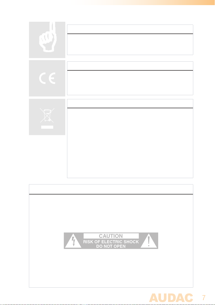
CAUTION - SERVICING
This product contains no user serviceable parts. Refer all servicing
to qualified service personnel. Do not perform any servicing
(unless you are qualified to)
EC DECLARATION OF CONFORMITY
This product conforms to all the essential requirements and further
relevant specifications described in following directives: 2014/30/
EU (EMC) and 2014/35/EU (LVD)
WASTE ELECTRICAL AND ELECTRONIC EQUIPMENT (WEEE)
The WEEE marking indicates that this product should not be
disposed with regular household waste at the end of its life cycle.
This regulation is created to prevent any possible harm to the
environment or human health.
This product is developed and manufactured with high quality
materials and components which can be recycled and/or reused.
Please dispose this product at your local collection point or
recycling centre for electrical and electronic waste. This will make
sure that it will be recycled on an environmentally friendly manner,
and will help to protect the environment in which we all live.
CAUTION
The symbols shown are internationally recognized symbols that warn about potential
hazards of electrical products. The lightning flash with arrow point in an equilateral
triangle means that the unit contains dangerous voltages. The exclamation point in
an equilateral triangle indicates that it is necessary for the user to refer to the users
manual.
These symbols warn that there are no user serviceable parts inside the unit. Do not
open the unit. Do not attempt to service the unit yourself. Refer all servicing to qualified
personnel. Opening the chassis for any reason will void the manufacturer’s warranty.
Do not get the unit wet. If liquid is spilled on the unit, shut it off immediately and take
it to a dealer for service. Disconnect the unit during storms to prevent damage.
Page 8

8
Page 9
9
Chapter 1
Connections and connectors
CONNECTION STANDARDS
The in- and output connections for AUDAC audio equipment are performed according
to international wiring standards for professional audio equipment.
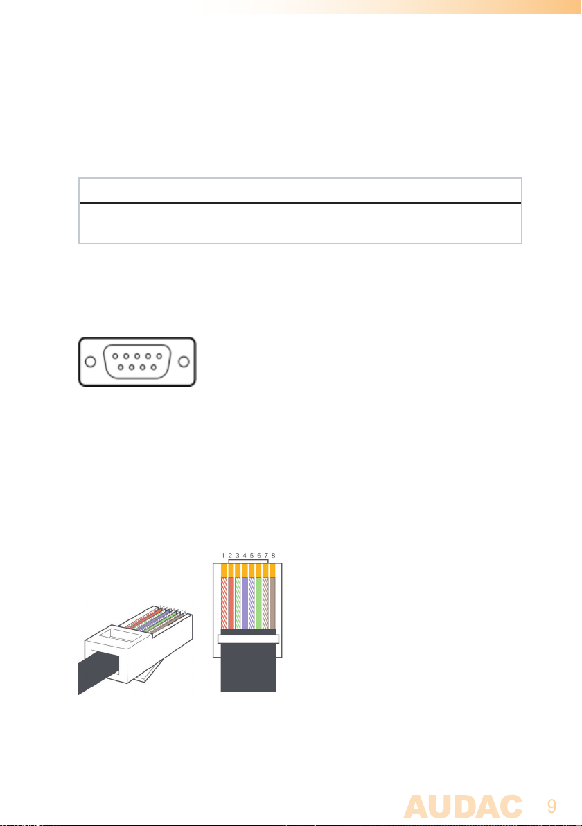
RS232 (serial connection interface):
For connection with home & industrial automation systems, controllable equipment, ...
Connection Standard RS232
PIN 2 APC100MK2 T X
PIN 3 APC100MK2 R X
PIN 5 GND
Settings 19200 Baud (default)
8 Bit
1 Stop bit
No parity
No Handshaking
RJ45 (RS485, Audio, +24V DC):
For connection to matrix systems / peripheral devices
Pin 1 White-Orange AUDIO A
Pin 2 Orange AUDIO B
Pin 3 White-Green +24V DC
Pin 4 Blue RS485 A
Pin 5 White-Blue RS485 B
Pin 6 Green GND
Pin 7 White-Brown AUDIO A
Pin 8 Brown AUDIO B
Page 10

10
Page 11
11
Chapter 2
Overview APC100MK2
Front panel APC100MK2
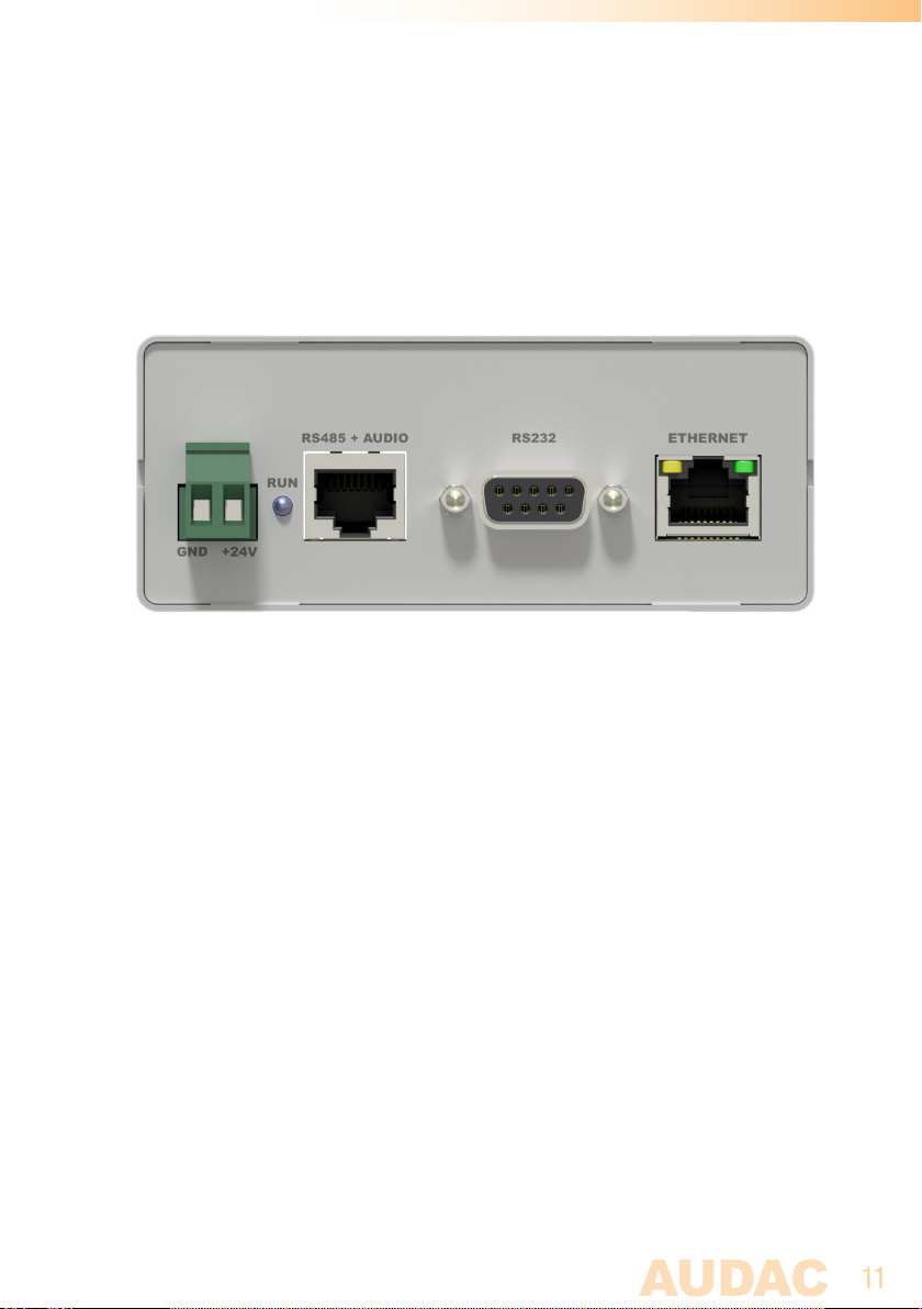
APC100MK2 Front panel
Various control and configuration ports are located on the front panel of the APC100MK2
together with the 24 Volts power connection.
1) 24 Volts power connector:
24 Volts DC mains power should be applied to this connector. Connect the wires of the
included power supply (PSD241) here. Mind the polarity markings when connecting the
power supply.
2) ‘RUN’ LED:
The blue ‘RUN’ LED will indicate the current operation mode of the device. When the
device is running in normal mode, this LED will blink with a constant frequency.
3) ‘RS485 + AUDIO’ RJ45 connector:
Connections to any peripheral such as wall panels, paging microphones, ... or matrix
systems should be made on this data bus connector. This data bus carries all audio and
control signals between the APC100MK2 and other devices. Connections should be
made using twisted pair CAT5E (when using analogue audio transfer) or CAT6 (when
using digital audio transfer) cabling.
This data bus is implemented twice (once on front and once on rear panel), both having
identical possibilities and specifications.
Page 12
12
4) RS232 control port:
The RS232 control port is implemented using a DB9 connector. Any communication
between the APC100MK2 and external control hardware equipped with an RS232 control
port can be made in this way. The pinout and communication protocol settings are
described in chapter 1 of this manual.
5) Ethernet connection:
The APC100MK2 is equipped with an Ethernet network connection implemented using
an RJ45 connector. The green and orange LED’s will indicate whether the network is
connected and active. Using this port, the APC100MK2 can be connected in any LAN
network.
Rear panel APC100MK2
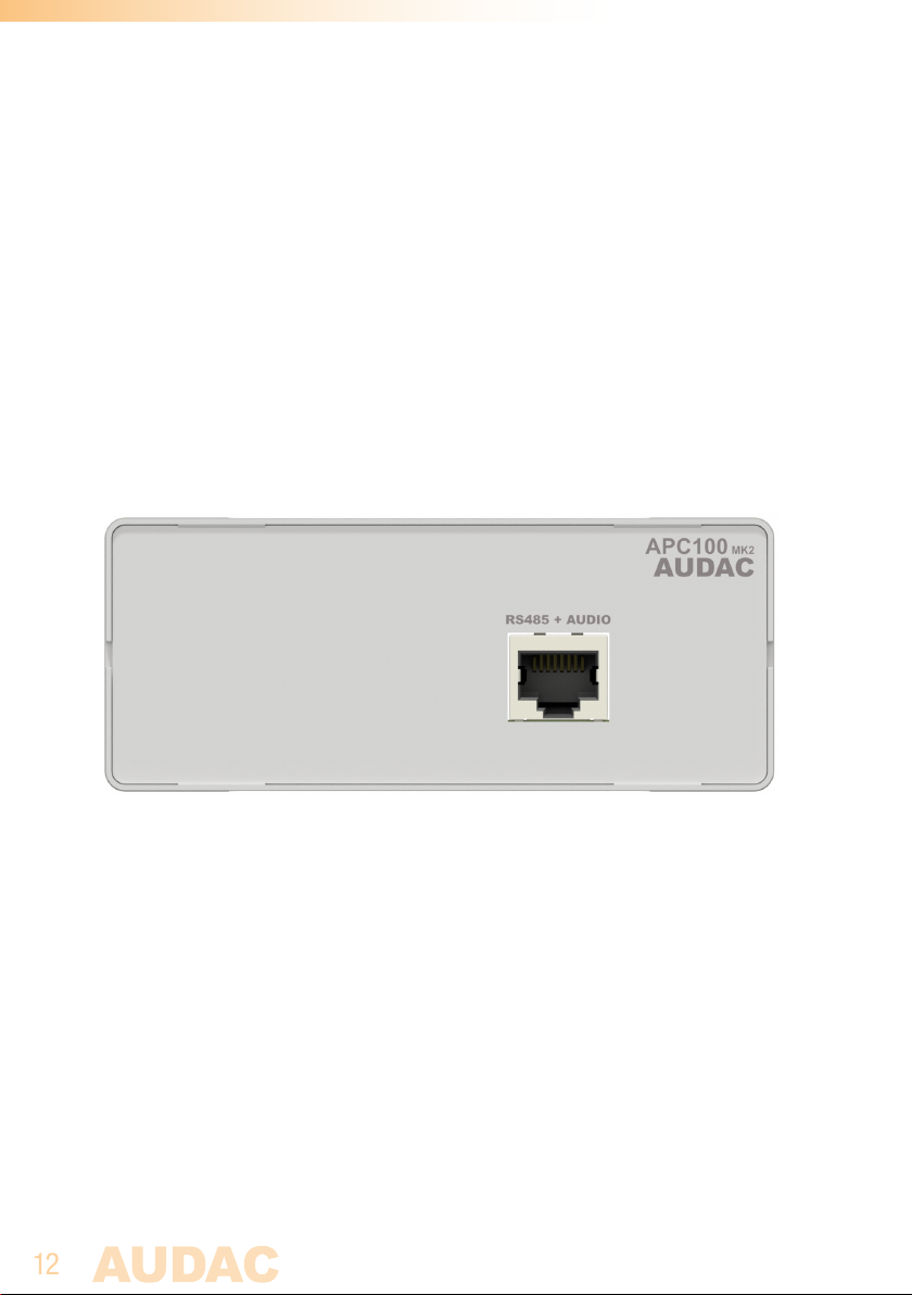
APC100MK2 Rear panel
‘RS485 + AUDIO’ RJ45 connector:
The rear panel of the APC100MK2 contains only one data bus connection. This data
bus connection has identical possibilities and specifications as the data bus connection
implemented on the front panel of the APC100MK2. When a connection between the
APC100MK2 and a peripheral interface or matrix system is made, the selection between
both connections can be freely chosen.
The advantage of the second implemented data bus makes the APC100MK2 applicable
to a connection between a peripheral device (wall panel, paging microphone, ... ) and a
matrix system. In this typical application one data bus connection can be used as input
while the second connection can be used as output.
Page 13

13
Chapter 3
Configuring the APC100MK2
The settings are configured in the web-based user interface of the APC100MK2. To get
access to these settings, it should get connected to a computer or LAN network through
an Ethernet connection. For more information about network connections and settings,
see IP basics in chapter 5.
The factory default IP address of the APC100MK2 is set to 192.168.0.19 4, make sure
this address is within the IP range of the network whereto its connected (sub net mask
255.255.255.0). If the default IP address is not within range of your LAN network, contact
your network specialist. The IP address can be changed in the configuration settings
menu but therefore a network connection must be established first!
Configuration interface
Start your default web browser and enter the IP address of the APC100MK2 in the address bar on top. (The factory default IP address is h t tp://19 2 .168.0.194)
Login screen
First the login screen will be displayed.
A password should be entered to get access to the configuration interface. After the correct
password is entered, click the “OK” button, and you will be redirected to the configuration
screen of the APC100MK2. (The factory default password for the APC100MK2 is ‘APC’)
NOTE
The passwords can be changed in the ‘Password settings’ menu.
Page 14
14
Configuration screen
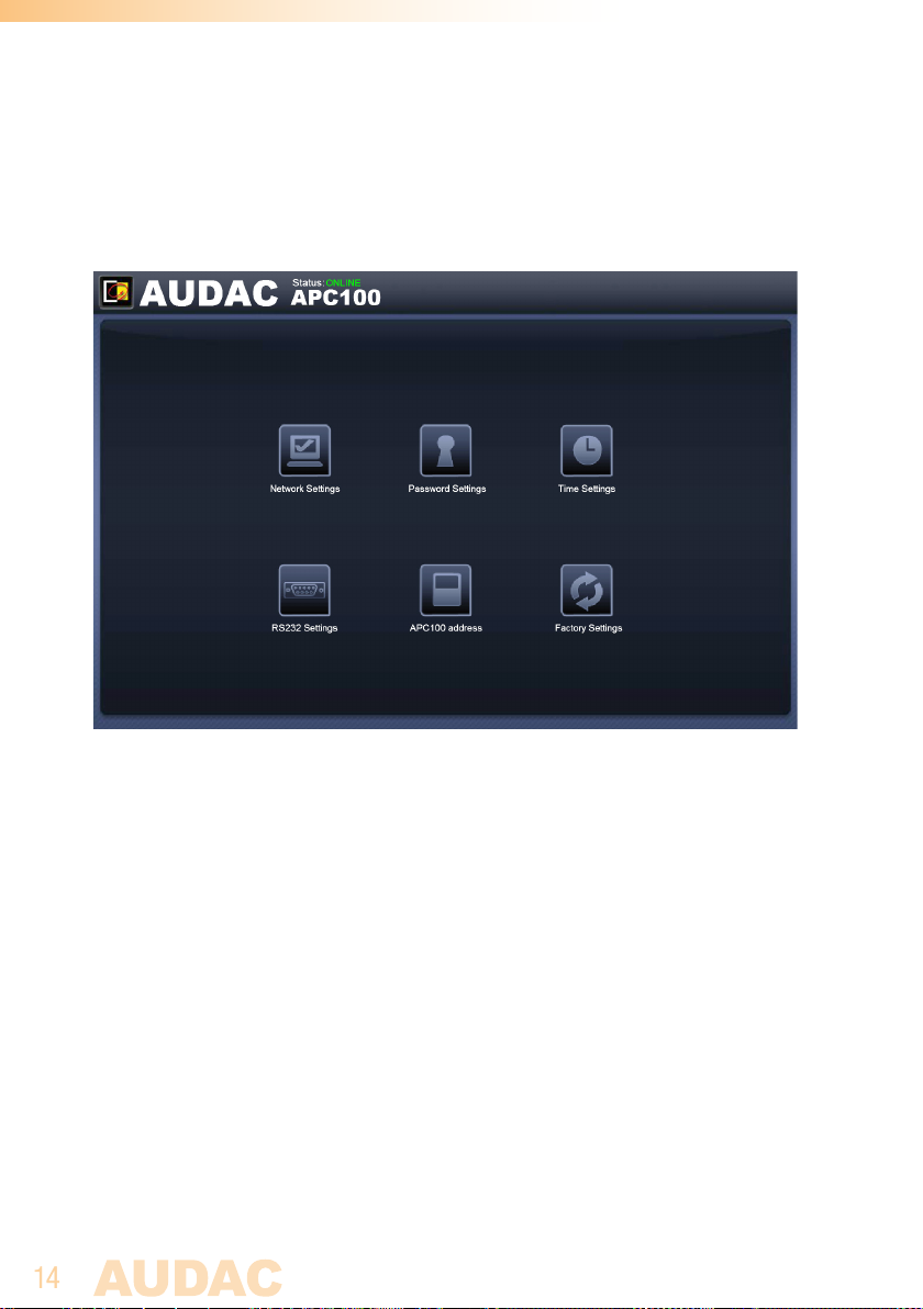
After the correct password has been entered, the configuration screen of the user interface will be loaded as shown below.
Configuration screen for APC100MK2
This window gives an overview of the configuration settings which can be adjusted in the
APC100MK2 web interface. Different icons are shown for ‘Network settings’, ‘Password
settings’, ‘Time settings’, ‘RS232 settings’, ‘APC100 address’ and ‘Factory settings’.
Click the particular button if you want to make any changes to the corresponding settings.
Connection status
In the top left corner of the window is the connection status indicated. When an active
connection is established, the connection status will indicate ‘ONLINE’ in a green color.
When the connection was temporary interrupted but restored, the connection status will
indicate ‘ONLINE’ in an orange color. When the connection status indicates ‘OFFLINE’,
there is currently no communication with the device.
Page 15
15
Network settings
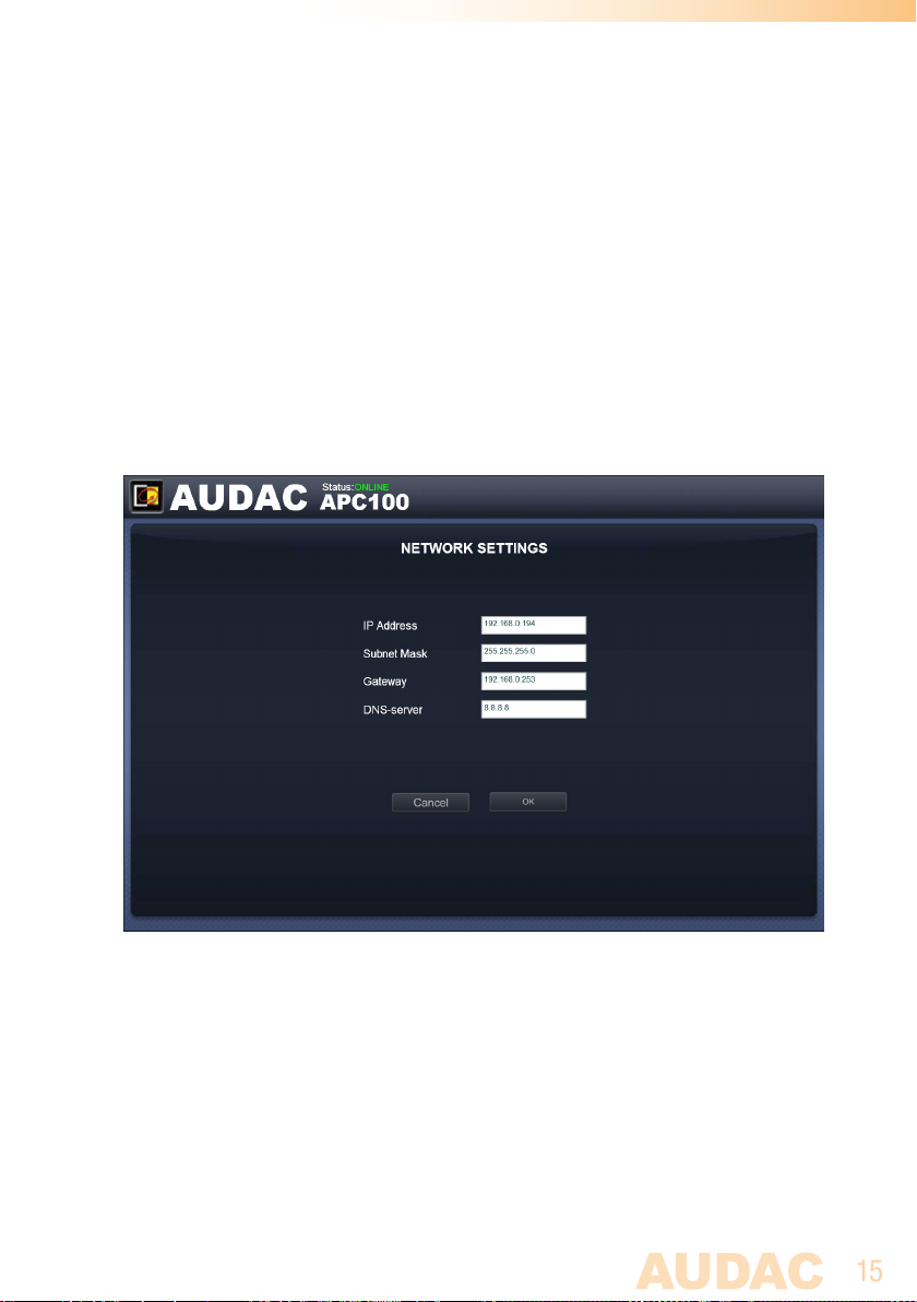
In this window, the network settings of the APC100MK2 can be adjusted.
The IP address is standard set to 192.168.0.194 and the subnetmask is standard set
to 255.255.255.0.
The settings can be changed by adjusting the parameters in the shown fields and pressing
OK. Once changed, the modified settings will take effect immediately and you will be
automatically redirected to the newly entered IP address.
For more information about network connections and settings, see IP basics in Chapter 5.
Network settings screen for APC100MK2
Page 16
16
Password settings
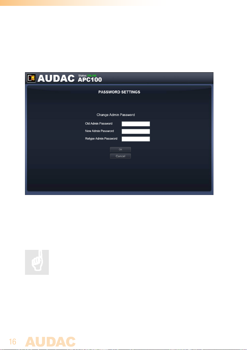
In this window the password for the APC100MK2 can be changed.
Password settings screen for APC100MK2
To change the password, enter the old password in the provided field and enter the new
password twice in the fields below. After this is all completed, push the OK button. If the
old password is correct and both new entered passwords are matching, the password
will be changed in the new one.
The factory default password is ‘APC’.
Page 17
17
Time settings
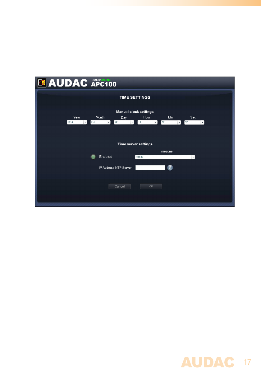
In this window the time settings for the APC100MK2 can be changed.
Time settings screen for APC100MK2
The current time and date for the APC100MK2 can be configured in this window.
The APC100MK2 act as a real-time-clock for synchronizing timer scheduled events
with other devices connected in your network. (when they are not including their own
real-time-clock)
The time and date settings (Manual clock settings) selection is done manually by selection
from the drop down lists. After the correct values are selected, the ‘OK’ button on the
bottom of the page should be clicked and the entered time & date will be saved. The
internal real-time clock holding the current time and date has an accuracy of 1 minute
/ month, meaning the set value may expire with a maximum of 1 minute / month.
A second option is synchronizing the internal clock constantly with a public time server
(time server settings). This function can be activated by clicking the ‘Enabled’ button.
Subsequently, the time zone in which the device is located should be selected. In case
the time server function has been selected, the APC100MK2 will try to synchronize every
few minutes with a public time server (through internet), making sure the current set
time is always accurate and won’t expire.
Page 18
18
When the APC100MK2 is connected to a LAN network without having access to internet,
the APC100MK2 time server can synchronize with a ‘Master’ time server in your LAN
network to avoid time expiring. In this case the IP address from the ‘Master’ time server
in your network should be entered in the ‘IP Address NTP server’ field. In all other cases
this field should be left blank.
When making changes to ‘Time server settings’ (timezone and/or IP address NTP server),
the function first need to be disabled before any changes are made to it, and need to
enable again to become effective.
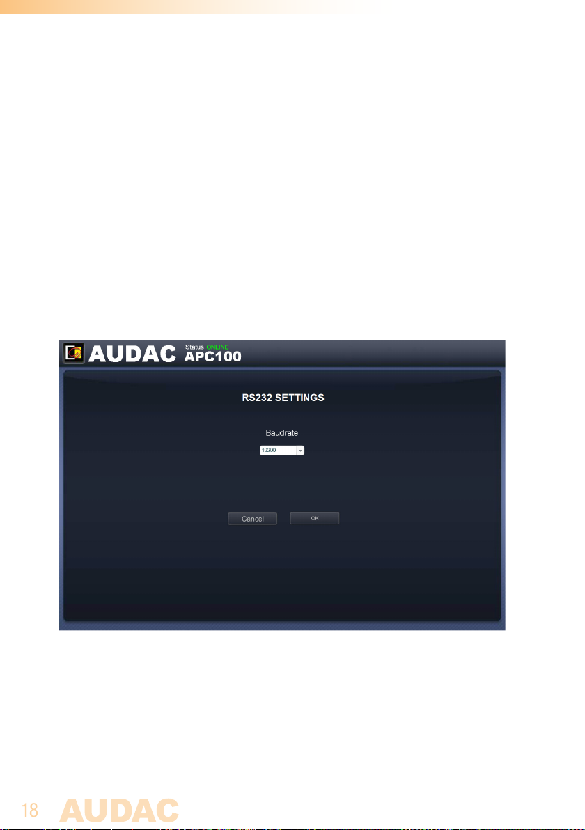
RS232 settings
In this window the RS232 settings (baud rate) for the APC100MK2 can be configured.
RS232 settings screen for APC100MK2
Depending of the baud rate compatibility for the connected device to the RS232
connection of the APC100MK2, the baud rate can be configured in this screen. Selection
is done through a dropdown box and is possible between various baud rates for 1200
/ 2400 / 4800 / 9600 / 14400 / 19200 / 28800 / 38400 / 56000 / 57600 and 115200
baud. The default configured baud rate is 19200 baud, which is functional with all other
available AUDAC products. Press OK to confirm the baud rate and before the change
will become effective.
Page 19
19
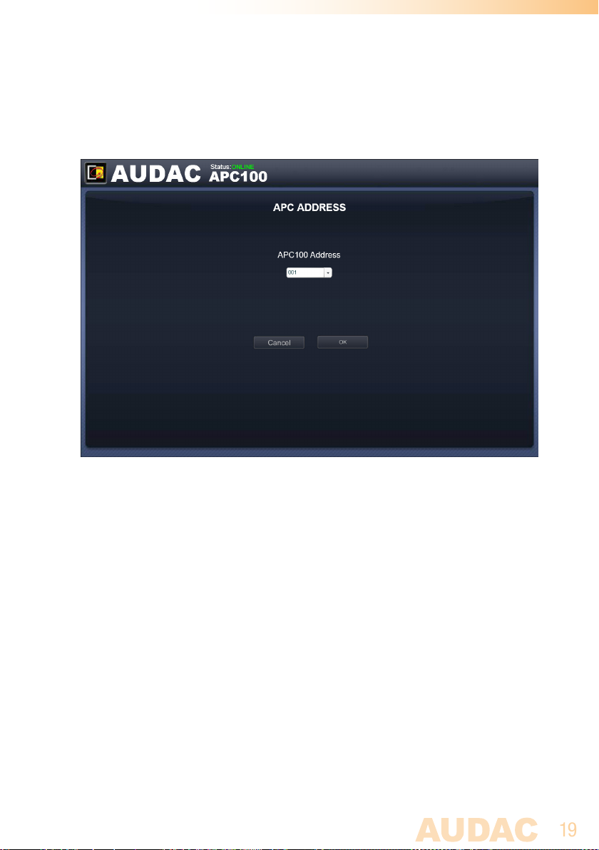
Address settings
In this window the address settings for the APC100MK2 can be configured.
Address settings screen for APC100MK2
The address is default set to ‘001’ and selectable using the drop down list in a range
of ‘001’ and ‘099’.
When multiple APC100MK2’s are used in one configuration or installation, every APC100MK2
should have an unique assigned address. It is recommended to use address ‘001’ for the first
connected APC100MK2 and increase by one for every subsequent connected APC100MK2.
When sending commands through serial or network communication, the device address
for the APC100 is always preceded by the letter ‘B’. Meaning for APC100 with device
address ‘001’, destination ‘B001’ shall always be used when sending commands.
Page 20
20
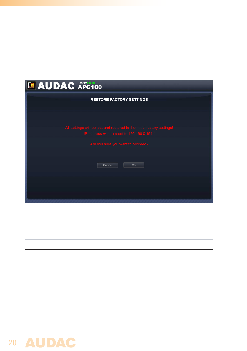
Factory settings
In the factory settings menu, all settings of the APC100MK2 will be set to factory default.
It does not recall the previously saved settings, but will recall the original factory settings
and all previously made settings will be lost.
Factory settings screen for APC100MK2
When clicking the ‘Factory settings’ button, a warning window will appear. If you proceed
by clicking the ‘OK’ button, all settings will be returned to factory default values.
ATTENTION
BE CAREFUL to press this button. All original factory settings will be recalled and all
custom settings will be lost.
Page 21

21
Chapter 4
Using the APC100MK2
The APC100MK2 universal configuration & control unit is a multifunctional device which
can be used as a configuration tool for matrix systems & peripherals, while another typical
application is the use as network gateway for various kinds of devices.
Using as a configuration tool
When using the APC100MK2 as a configuration tool, it will establish the physical link
between the peripheral device (wall panel, paging console, ...) and the ‘AUDAC system
manager’ software allowing to create and upload or download specific configurations.
The ‘AUDAC system manager’ software is freely available and can be downloaded from
the AUDAC website.
This software tool (compatible with windows, mac and linux) detects all ‘smart’ devices
with their peripherals in your system and allows extended configuration, update and
backup functions of the equipment.
Using as a gateway
When the APC100MK2 is used as a gateway, it allows connection to and control through
any TCP/IP based network for all devices containing an RS232 or RS485 interface. The
baud rate is configurable in the APC100 settings menu.S
The commands sent to the IP address of the APC100MK2 on port 5001 will be translated
and converted to commands on the RS232 and RS485.
This way, any device containing RS232 (Eg: power amplifier) can be connected to your
LAN network and controlled through an TCP/IP based automation system.
Page 22

22
Chapter 5
Additional information
IP Basics
Many AUDAC products are controllable by Ethernet. The Ethernet connection which
is used on the AUDAC products is TCP/IP based like 99% of the computer networks.
There are some basics which you need to know to successfully make a TCP/IP Ethernet
connection.
The data in TCP/IP networks is always send in packages, all these packages must be
delivered to a unique address, just like the mailman delivers mail to your home mailbox.
In TCP/IP networks, this address is called the “IP address”. The IP address is always a
number in the following format “192.168.000.001”. As you can see, this address consists
of 4 separate numbers ranging from “000” to “255”.
In simple terms, only the last number of an IP address can be different
within a network, so there is a maximum of 256 unique addresses within
a network, ranging from “xxx.xxx.xxx.000” to “xxx.xxx.xxx.255”. The first
three numbers have to be the same to make communication between several
devices possible, otherwise the devices can not communicate with each other.
Example:
Device 1: IP address: 192.168.000.001
Device 2: IP address: 192.168.000.002
Device 3: IP address: 192.168.001.003
In this example, Device 1 can communicate with Device 2, but not with Device 3, because
the first three numbers have to be the same. These first three parts are called the “IP
range”, so the devices have to be in the same “IP range” to communicate with each other.
Page 23
23
The “IP ranges” of home and office networks are defined by the network administrator,
this means that the IP range of your home or office network can be different from another
network. AUDAC products have the following default IP address: “192.168.0.xxx”, this
means the standard IP range of AUDAC products is “192.168.000.xxx”. If your network is
using a different IP range, the AUDAC products will not be accessible from your network.
You can change the IP address of the AUDAC products to make them work properly in
your network. This can be done in the settings menu, and is described extensively in
the “Settings” chapter of this user manual.
Of course, to make changes to the settings menu of the AUDAC products, you need to have
access to the user interface on the product’s web page. This can be done by temporarily
giving your computer an IP address within the IP range of the AUDAC product, for example
“192.168.0.193”. After the IP address of your computer is within the IP range of the
product, the user interface is accessible and the IP address of the product can be changed
to an IP address within the IP range of your network. If the IP address of the product is
within the IP range of your network, you can change the IP address of your computer to it’s
former IP address and the product should work properly in your home or office network.
Ask your network administrator for help if you are not familiar with networks.
Summary
- All devices must have a unique IP address
- All devices must be within the same IP range
Page 24

24
Technical specifications
Data connections Ethernet (RJ45)
2 x RS485 + Audio (RJ45)
RS232 (DB9)
RS232 specifications Baud rate selectable (Default 19200)
1200 / 2400 / 4800 / 9600 / 14400 /
19200 / 28800 / 38400 / 56000 /
57600 / 115200 Baud
8 Bit
1 Stop bit
No parity
No Handshaking
Power consumption < 1 Watt
Power supply 24V DC
PSD241 switching power supply included
100 ~ 240V AC / 47~63 Hz
Dimensions (W x H x D) 108 x 44 x 164 mm
Weight 0.8 Kg (incl power supply)
Packaging Carton box
Shipping weight & Volume 1.12 Kg - 0.0078 Cbm
Optional accessories MBS1xx Mounting brackets
 Loading...