

Page 1
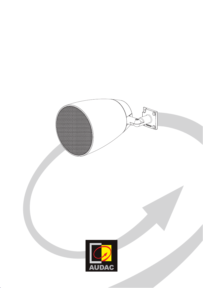
ALTIx4 Series
User & Installation
Manual
www.audac.eu
Page 2

2
Page 3

3
Introduction
2-Way design wall sound projectors
The ALTIxM series are design wall sound projectors, designed for background and
foreground music in both indoor and outdoor applications. They are variants of the ALTI
series pendant loudspeakers allowing the same audio system design and identity for
throughout the entire installation in case some area’s are not allowing pendant solutions
being used due to the ceiling heights or structures. Typical applications are big scale
retail environments, warehouses and other large open spaces
The elegant construction is finished using high grade materials and fitted with premium
acoustic components. This guarantees clear speech intelligence and a warm and detailed
sound reproduction.
Mounting the speaker is done through a 2-way revolving mounting bracket system,
and connections are made through a waterproof AWX-5 connection terminal. An
innovatively designed rear cover of the speaker can be placed after installation and
hides the connection.
The 2-way combination with a coaxially mounted 1” soft dome tweeter and is fitted
with a phase plug for excellent off axis performance. The high quality polypropylene
enclosure and acoustic engineering craftmanship guarantees premium performance
for demanding applications.
They come in two different models (ALTI4M and ALTI6M) in terms of size and power
handling. A multi-tapping line transformer allows them to be connected to 70V/100V
public address systems with various power settings, while connections in low impedance
(16Ω) systems are also possible.
Page 4

4
Precautions
READ FOLLOWING INSTRUCTIONS FOR YOUR OWN SAFETY
• ALWAYS KEEP THESE INSTRUCTIONS FOR FUTURE REFERENCE. NEVER
THROW THEM AWAY
• ALWAYS HANDLE THIS UNIT WITH CARE
• CLEAN ONLY WITH DRY CLOTH
• HEED ALL WARNINGS AND FOLLOW ALL INSTRUCTIONS
• NEVER EXPOSE THIS EQUIPMENT TO RAIN, MOISTURE, ANY DRIPPING OR
SPLASHING LIQUID. AND NEVER PLACE AN OBJECT FILLED WITH LIQUID ON
TOP OF THIS DEVICE
• DO NOT INSTALL THIS UNIT NEAR ANY HEAT SOURCES SUCH AS RADIATORS
OR OTHER APPARATUS THAT PRODUCE HEAT
• DO NOT PLACE THIS UNIT IN ENVIRONMENTS WITH A HIGH LEVEL OF DUST,
HEAT, MOISTURE OR VIBRATION
• THIS UNIT IS DEVELOPED FOR INDOOR USE ONLY. DO NOT USE IT OUTDOORS
• ONLY USE ATTACHMENTS & ACCESSORIES SPECIFIED BY THE
MANUFACTURER.
• ONLY INSTALL THE SPEAKER IN LOCATIONS THAT CAN STRUCTURALLY
SUPPORT THE WEIGHT OF THE SPEAKER. IGNORING THIS CAN BRING THE
SPEAKER DOWN.
• DO NOT USE ANY OTHER METHOD THAN SPECIFIED TO MOUNT THE
SPEAKER. IF EXTREME FORCE IS APPLIED TO THE SPEAKER, IT COULD FALL
DOWN
• ATTACH A SAFETY WIRE TO THE SPEAKER WHEN IT IS MOUNTED HIGH UP.
ONLY USE INDUSTRY-ACCEPTED RIGGING TOOLS AND METHODS
• CAREFULLY CHECK THE UNIT’S CONDITION AFTER UNPACKING.
IF THERE IS ANY DAMAGE TO THE CARTON BOX OR THE UNIT ITSELF,
INFORM YOUR VENDOR IMMEDIATELY.
Page 5
5
CAUTION
• USE CABLES OF THE RIGHT GAUGE TO CONNECT THE LOUDSPEAKER
• USE CABLES WITH CLEAR COLOR CODING INDICATING THE POLARITY AND
MAINTAIN THE SAME POLARITY THROUGHOUT THE WHOLE SYSTEM.
• ONLY USE THE CORRECT AMPLIFIER OUTPUT VOLTAGE AND IMPEDANCE.
EXCEEDING THESE LIMITS COULD CAUSE FIRE OR OTHER FAILURES.
AVOID EXPLOSIONS: DO NOT USE THE SPEAKER AROUND GASOLINE,
THINNER OR OTHER COMBUSTIBLES
• AVOID ELECTRIC SHOCKS: SWITCH OFF THE AMPLIFIER WHEN CONNECTING
THE LOUDSPEAKER
• DO NOT USE THE LOUDSPEAKER FOR AN EXTENDED PERIOD OF TIME AT
DISTORTED SOUND. THIS COULD CAUSE PERMANENT DAMAGE.
CAUTION - SERVICING
This product contains no user serviceable parts. Refer all servicing
to qualified service personnel. Do not perform any servicing
(unless you are qualified to do so.)
EC DECLARATION OF CONFORMITY
This product conforms to all the essential requirements and further
relevant specifications described in following directives: 2014/30/
EU (EMC) and 2014/35/EU (LVD)
WASTE ELECTRICAL AND ELECTRONIC EQUIPMENT (WEEE)
The WEEE marking indicates that this product should not be
disposed with regular houshold waste at the end of its product
life. This regulation is created to protect both the environment
and human health.
This product is developed and manufactured with high quality
materials and components which can be recycled and/or reused.
Please dispose this product to your local collection point or
recycling centre for electrical and electronic waste. This will
make to sure that it will be recycled on an environmentally friendly
manner, and will help to protect the environment in which we all
live.
Page 6
6
Installing the ALTI
2-Way revolving mounting bracket
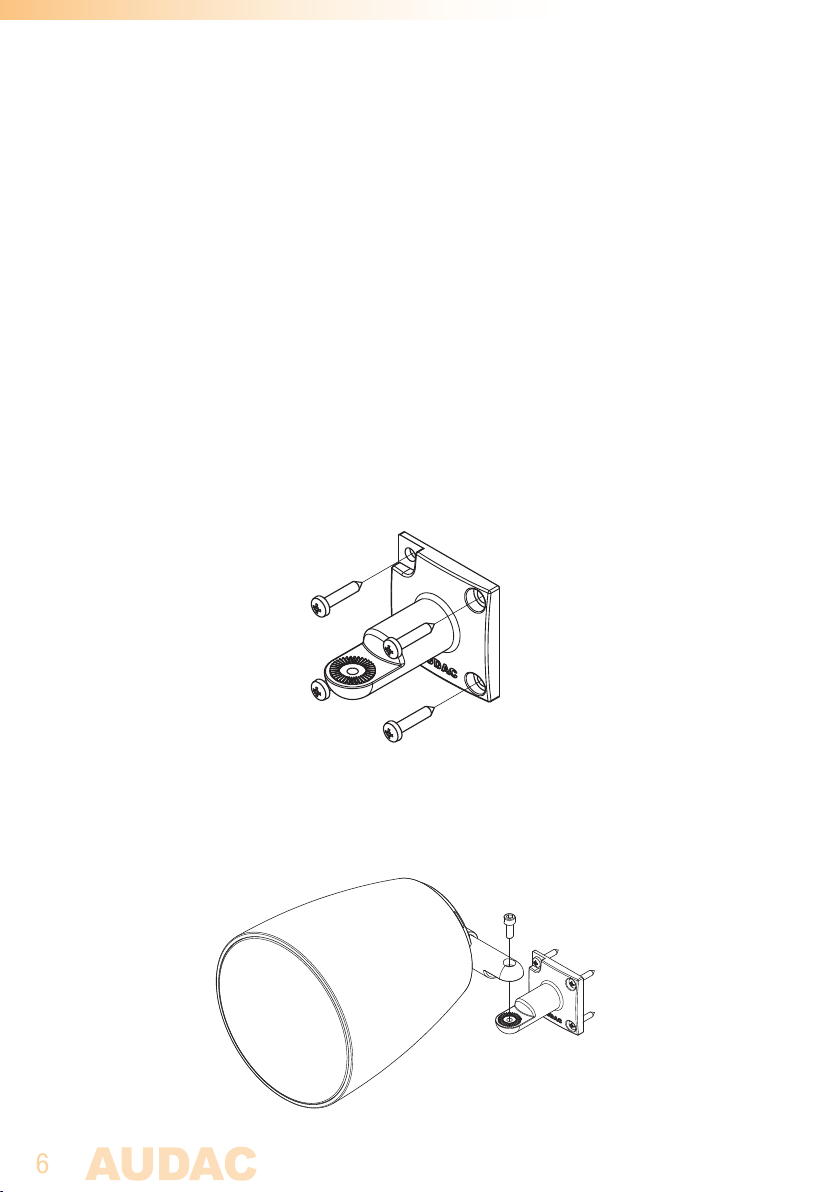
The ALTIxM speakers are delivered with a 2-way revolving wall bracket system, allowing
the speaker for being installed at each location. The wall bracket can be installed in a
horizontal and vertical direction, allowing the speaker for being focussed into any desired
direction, even when the installation distance to the wall or ceiling is limited.
The two-way revolving bracket is made out of die-cast zinc alloy material which ensures
a solid and secure mounting of the loudspeaker. The wall bracket has to be fixed to the
wall by four screws. The used fasteners shall be chosen according to the mounting
surface where the speaker will be installed to (brick, concrete, wood, ...). The holes
should be provided in a quadrangular shape as shown in following drawing. The mutual
distance between the holes is 45 x 45 mm.
Once this part is correctly mounted to the desired location on the wall or ceiling, the
cabinet can be assembled to the bracket. This is done through inserting the supplied
bolt (M6) through the hole in the bracket (speaker part) and tighten it into the wall or
ceiling part.
Page 7
7
Connecting the speaker
The ALTIxM speakers are designed for use in 70V and 100V public address systems.
Before connecting the loudspeakers to the system, make sure the amplifier is switched
off.
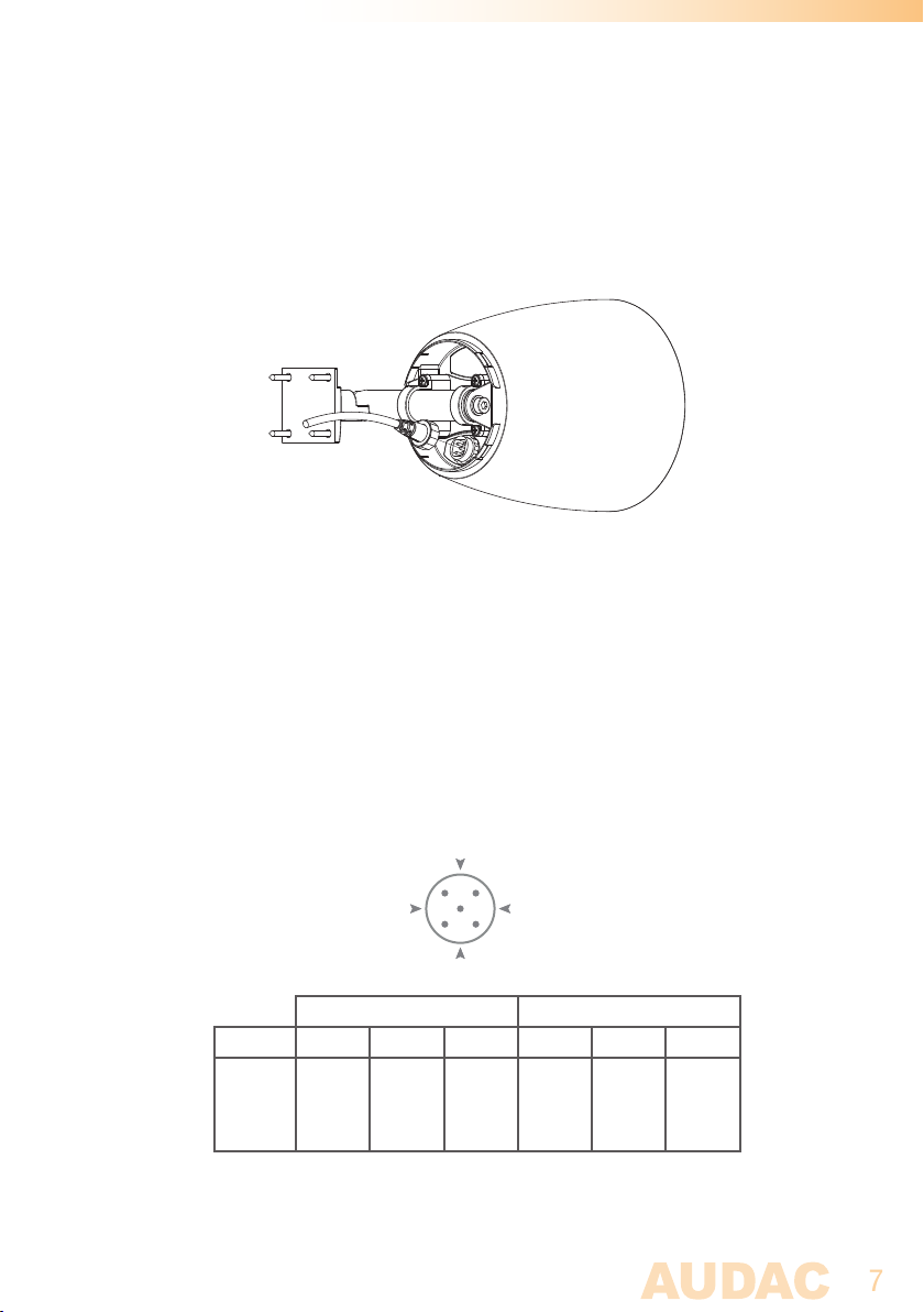
The power tap selection of the ALTIxM outdoor series speakers is made through the
orientation of the waterproof AWX5™ connector on the rear side of the loudspeaker. This
allows connection to the amplifier output using the included connection cable (AWC07)
with a length of 0.7 meter. The blue conductor shall always be connected to the COM
terminal of the amplifier output and red conductor shall always be connected to the
positive terminal of the amplifier output. Mind the polarity markings when wiring the
loudspeaker cables.
The power tap selection is made by adjusting the rotation angle of the waterproof
connector. A dot on the connector indicates the direction of the connector and the various
power tappings are indicated on a label attached to the speaker and in the image below.
A
B
ALTI4M ALTI6M
Tapping 100V 70V Imp. 100V 70V Imp
DO NOT U SE
A
24 W 12 W 417 Ω 60 W 30 W 167 Ω
B
12 W 6 W 833 Ω 30 W 15 W 333 Ω
C
After the connector is correctly plugged into the socket, make sure the screw nut is well
tightened to guarantee the IP55 waterproof performance of the loudspeaker.
24 W 208 Ω
16 Ω
C
DO NOT U SE
60 W 83 Ω
Page 8
8
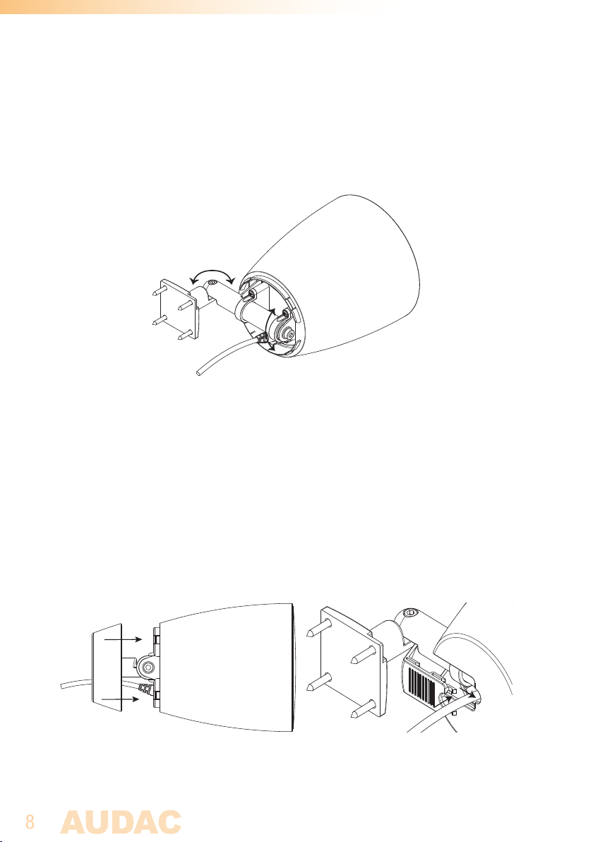
Adjusting the angles
The speakers direction can be adjusted in 2 different angles. The image below shows
in which direction the adjustment is possible. The direction of the speakers can be done
by loosen the screws, positioning the speakers and firmly tighten the screws for fixation.
Attaching the rear cover
The last step in the installation process of the loudspeaker is the assembly of the cover
to the rear side of the cabinet. The cover is designed in two parts, a cover and a sliding
tab which can be taken out, allowing it being assembled after the speaker is mounted
and connected.
Position the cover on the rear of the cabinet, and it will click and latch in position. Once
assembled, the sliding tab can be inserted to the cover and can be slide into position,
offering a nice and clean outlook of the cabinet.
Page 9

9
Additional Information
Technical specifications
ALTI4M ALTI6M
Max Power 60 Watt 120 Wat t
RMS Power 30 Watt 60 Watt
Nominal impedance 16 Ohm 16 Ohm
Line transformer taps 208 Ω – 70V/24W 83 Ω – 70V/60W
417 Ω – 100V/24W - 70V/12W 167 Ω – 100V/60W - 70V/30W
833 Ω – 100V/12W - 70V/6W 333 Ω – 100V/30W - 70V/15W
Sensitivity 1W/1m 80 dB 83 dB
Sound pressure Max W / 1m 95 dB 101 dB
Frequency response (±3 dB) 85 Hz - 20 kHz 75 Hz - 20 kHz
Frequency range (-10 dB) 65 Hz - 20 Hz 61.5 Hz - 20 Hz
Drivers 1” HF dome tweeter 1” HF dome tweeter
4” MF/LF woofer 6.5” MF/LF woofer
Cross-over network Passive built-in Passive built-in
Connectors AWX5™ waterproof connector AWX5™ waterproof connector
Connection cable length 0.7 m 0.7 m
Mounting & handling 2-Way revolving die-cast metal
mounting bracket
Construction Polypropylene housing Polypropylene housing
Front finish Fine perforated aluminum grill Fine perforated aluminum gril
Ingress protection IP55 IP55
Operation temperature
range
-20°C to +50°C -20°C to +50°C
2-Way revolving die-cast metal
mounting bracket
Colour White ALTI4M/W (RAL9003) ALTI6M/W (RAL9003)
Black ALT4M/B (RAL9005) ALTI6M/B (RAL9005)
Dimensions (Ø x H) 205 x 170 x 257 mm 235 x 230 x 336 mm
Weight 1.5 Kg 4 Kg
Page 10

10
Packaging Carton box Carton box
Shipping weight & Volume 1.69 Kg - 0.014 Cbm 4.25 Kg - 0.034 Cbm
Accessories included AWC07 0.7m connection cable AWC07 0.7m connection cable
2-Way revolving die-cast metal
mounting bracket
Optional accessories AWC25 2.5 m connection cable AWC25 2.5 m connection cable
AWC50 5 m connection cable AWC50 5 m connection cable
2-Way revolving die-cast metal
mounting bracket
Page 11

11
Notes
Page 12

12
Notes
 Loading...