

Page 1
Page 2
1 About This Manual ....................................................................................... 3
2 Caution Statements...................................................................................... 4
3 General Description..................................................................................... 6
4 Specifications.................................................................................................... 9
5 Receiving and Storage.............................................................................. 16
6 Installation ...................................................................................................... 17
7 Internal Wiring –X10................................................................................ 36
8 Keypad and Feedback............................................................................... 37
9 Configuration................................................................................................ 38
10 Commissioning ............................................................................................ 57
Contents
1
1.1 User Manual Version............................................................................................................. 3
3.1 Overview...................................................................................................................................... 6
3.2 Feature List.................................................................................................................................. 6
3.3 Key Features............................................................................................................................... 7
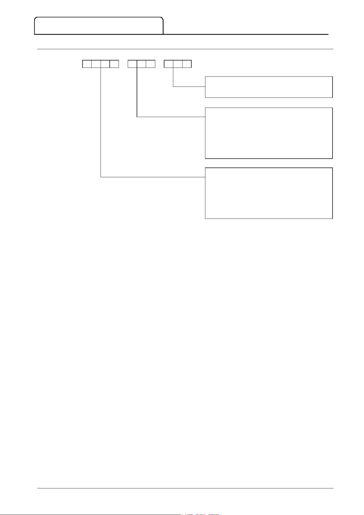
3.4 Model Code ............................................................................................................................... 8
4.1 Key Components..................................................................................................................... 9
4.2 Dimensions and Weights..................................................................................................10
4.3 General Technical Data .....................................................................................................11
4.4 Panel Specifications...............................................................................................................13
5.1 Receiving.....................................................................................................................................16
5.2 Storage.........................................................................................................................................16
CONTENTS
6.1 Clearance Requirements...................................................................................................17
6.2 Foundation Requirements................................................................................................18
6.3 Fastening Panels to the Foundation............................................................................19
6.4 Earth Termination .................................................................................................................20
6.5 Assembling the Switchgear Line-up............................................................................21
6.6 Mounting Instructions - Power Assembly................................................................23
6.7 Mounting Instructions - Controller..............................................................................25
6.8 Power Terminations ............................................................................................................26
6.9 Earth Terminations ...............................................................................................................28
6.10 Control Terminations..........................................................................................................28
6.11 Wiring Terminations on the Controller...................................................................28
6.12 Wiring Terminations on the Power Interface Board........................................29
6.13 Ground Current.....................................................................................................................30
6.14 Power Circuits.........................................................................................................................31
8.1 The Controller........................................................................................................................37
8.2 Menu Shortcuts ......................................................................................................................37
8.3 Displays........................................................................................................................................37
9.1 Programming Menu..............................................................................................................38
9.2 Standard Menu........................................................................................................................39
9.3 Extended Menu......................................................................................................................40
9.4 Load/Save Settings................................................................................................................43
9.5 Parameter Descriptions .....................................................................................................43
10.1 Commissioning Menu (Tools)........................................................................................57
10.2 Set Date and Time ...............................................................................................................57
10.3 Simulation Tools.....................................................................................................................57
10.4 Input/Ouput Status...............................................................................................................59
10.5 Reset Thermal Models .......................................................................................................60
710-13937-00C MVS Panel User Manual 1
Page 3
CONTENTS
11 Monitoring...................................................................................................... 62
12 Operation....................................................................................................... 64
13 Troubleshooting.......................................................................................... 72
14 Maintenance.................................................................................................. 78
15 Appendix........................................................................................................ 83
10.6 Low Voltage Test Mode....................................................................................................60
1
11.1 Logs Menu.................................................................................................................................62
12.1 Start, Stop and Reset Commands ...............................................................................64
12.2 Using the Soft Starter to Control a Motor.............................................................64
12.3 Using the MVS to Control a Slip-Ring Motor.......................................................65
12.4 Operating States ....................................................................................................................68
12.5 Motor Protection...................................................................................................................69
12.6 Operating Feedback.............................................................................................................70
13.1 Protection Responses .........................................................................................................72
13.2 Trip Messages ..........................................................................................................................72
13.3 General Faults..........................................................................................................................76
14.1 Safety ............................................................................................................................................78
14.2 Maintenance Schedule........................................................................................................78
14.3 Tools required.........................................................................................................................78
14.4 Thermal Image ........................................................................................................................78
14.5 Contactor Maintenance.....................................................................................................78
14.6 Isolation Switch Maintenance.........................................................................................79
14.7 Isolator Microswitch Adjustment..................................................................................79
14.8 Phase Arm Assembly Alignment (model V13)....................................................80
14.9 Removing Phase Arms (model V13)..........................................................................81
15.1 Parameter Defaults...............................................................................................................83
15.2 Accessories................................................................................................................................86
2 MVS Panel User Manual 710-13937-00C
Page 4
WARNING
CAUTION
NOTE
1 About This Manual
© 2015 AuCom Electronics LLtd. All Rights Reserved.
The examples and diagrams in this manual are included solely for illustrative purposes. The information contained
in this manual is subject to change at any time and without prior notice. In no event will responsibility or liability be
accepted for direct, indirect or consequential damages resulting from the use or application of this equipment.
W
Indicates a hazard that may cause personal injury or death.
C
Indicates a hazard that may damage the equipment or installation.
Provides helpful information.
1.1 User Manual Version
This user manual (710-13937-00C) is compatible with MVS soft starters using version 1.29 control software and
version 2.30 interface software. For other software versions, please contact AuCom for the correct user manual.
The control software version is displayed on the Controller screen at power up.
ABOUT THIS MANUAL
Ready
Welcome
1.05 / 1.29 / 2.30
Software versions: Controller, control software, interface software
As AuCom is continuously improving its products it reserves the right to modify or change the specification of its products at any
time without notice. The text, diagrams, images and any other literary or artistic works appearing in this document are
protected by copyright. Users may copy some of the material for their personal reference but may not copy or use material for
any other purpose without the prior consent of AuCom Electronics Ltd. AuCom endeavours to ensure that the information
contained in this document including images is correct but does not accept any liability for error, omission or differences with the
710-13937-00C MVS Panel User Manual 3
finished product.
Page 5
CAUTION STATEMENTS
WARNING
- ELECTRICAL SHOCK HAZARD
SHORT CIRCUIT
GROUNDING AND
BRANCH CIRCUIT PROTECTION
ARC FLASH HAZARD
2 Caution Statements
Caution Statements cannot cover every potential cause of equipment damage but can highlight common causes of
damage. It is the installer's responsibility to read and understand all instructions in this manual prior to installing,
operating or maintaining the equipment, to follow good electrical practice including applying appropriate personal
protective equipment and to seek advice before operating this equipment in a manner other than as described in
this manual.
Read and understand the entire manual before installing operating, or maintaining the MVS. Follow all
applicable local and national codes.
Apply appropriate personal protective equipment (PPE) and follow safe electrical work practices.
Use only electrically insulated tools and clothing and insulated protective gear when working around
electrical equipment.
Disconnect all power and ensure that the MVS is de-energised before servicing the equipment.
Do not rely on visual indications such as switch position or fuse removal for determining a de-energised
condition. Always assume that a terminal is energised until it is checked with a properly rated meter to
ensure that a terminal is de-energised and grounded.
Isolate the MVS completely from the power supply before attempting any work on the MVS or motor.
Always use a properly rated voltage sensing device to confirm power is off.
Before servicing the MVS, ensure that all static charge has been discharged by grounding it with an
appropriate grounding device.
Metal swarf in the cabinet can cause equipment failure.
Do not apply voltage to the control input terminals. These are active 24 VDC inputs and must be
controlled with potential free contacts.
Contacts or switches operating the control inputs must be suitable for low voltage, low current switching
(ie gold flash or similar).
Cables to the control inputs must be segregated from mains voltage and motor cabling.
Some electronic contactor coils are not suitable for direct switching with PCB mount relays. Consult the
contactor manufacturer/supplier to confirm suitability.
W
The MVS contains dangerous voltages when connected to mains voltage. Only a qualified electrician should
carry out the electrical installation. Improper installation of the motor or the MVS may cause equipment
failure, serious injury or death. Follow this manual and local electrical safety codes.
The MVS is not short circuit proof. After severe overload or short circuit, the operation of the MVS should
be fully tested by an authorised service agent.
It is the responsibility of the user or person installing the MVS to provide proper grounding and branch circuit
protection according to local electrical safety codes.
Medium voltage equipment has a potential risk of arc flash. When insulation or isolation between electrified
conductors is breached or can no longer withstand the applied voltage, a short circuit occurs through the air.
This may cause a phase-to-ground and/or a phase-to-phase fault.
Although unlikely, arc fault can be caused by:
Contamination in the insulation caused by deterioration over time
Inadequate insulation system on cable terminals
Overvoltage
Incorrect protection coordination settings
Overheating of the contact area, due to incorrect tightening of connections
Introduction of foreign matter, including swarf, vermin, tools or maintenance equipment left in the
starter
-
4 MVS Panel User Manual 710-13937-00C
AuCom medium voltage equipment has been designed to mitigate an arc fault, however it is the
responsibility of the site engineer to ensure that personnel are protected from serious injury that may result
from an arc fault.
Page 6
CAUTION STATEMENTS
STORAGE
S
The MVS must be stored in its original packaging in a clean and dry environment. The MVS should be
unpacked only after the equipment room is ready for installation. Particular care should be taken to avoid
exposure of the electronics to cement and/or concrete dust.
710-13937-00C MVS Panel User Manual 5
Page 7
GENERAL DESCRIPTION
Starting
Stopping
Protection
Extensive input and output options
Comprehensive feedback
Power connection
Accessories (optional)
3 General Description
3.1 Overview
The MVS provides compact and robust soft start solutions for control of medium voltage motors. MVS soft
starters provide a complete range of motor and system protection features and have been designed for reliable
performance in the most demanding installation situations.
The two primary components of a MVS soft starter are:
a power assembly
a controller module
The power assembly and controller module are supplied as a pair and share the same serial number. Care should
be taken during installation to ensure that the correct controller and power assembly are used together.
3.2 Feature List
S
Constant Current
Current Ramp
S
Coast To Stop
Soft stop
P
Undervoltage / Overvoltage
Mains frequency
Phase sequence
Shorted SCR
Motor Overload (thermal model)
Instantaneous Overcurrent (two stages)
Time-overcurrent
Ground Fault
Undercurrent
Current Imbalance
Motor thermistor
Excess Start Time
Power circuit
Auxiliary trip
E
Remote control inputs
(3 x fixed, 2 x programmable)
Relay outputs
(3 x fixed, 3 x programmable)
Analog output
(1 x programmable)
Serial port (with module)
C
Starter status LEDs
Date and time stamped event logging
Operational counters (number of starts, hours-run,
kWh)
Performance monitoring (current, voltage, power
factor, kWh)
User-programmable monitoring screen
Multi-level password protection
Emergency stop pushbutton
P
50 A to 500 A, nominal
2300 VAC to 13800 VAC
A
Communication modules: Ethernet (Profinet,
Modbus TCP, Ethernet/IP), Profibus, DeviceNet,
Modbus RTU, and USB
Synchronous motor control
PC software
Overvoltage protection
Control supply transformer
MV/LV Control transformer
6 MVS Panel User Manual 710-13937-00C
Page 8
3.3 Key Features
Example:
Example:
NOTE
NOTE
MVS soft starters offer several special functions to ensure ease of use and to provide optimal motor control in all
environments and applications.
Customisable Protection
The MVS offers comprehensive protection to ensure safe operation of the motor and soft starter. The protection
characteristics can be customised extensively to match the exact requirements of the installation.
Use
4 Protection Settings
E
Undercurrent Delay
Use
16 Protection Action
Each protection can be set to trip the starter, activate a warning flag, or be ignored. All protection activations are
recorded in the event log, regardless of the protection class setting.
write to log). The default response is trip.
MVS soft starters have built-in trip points to ensure operation remains within the soft starter's
capability. These internal trips cannot be overridden. Certain faults within the MVS will also prevent
the soft starter from operating. Refer to
GENERAL DESCRIPTION
on page 45 to set the conditions in which each protection mechanism will activate.
use parameter 4C
on page 56 to select the soft starter's response when a protection mechanism activates.
Use parameter 16C
Undercurrent
to set a delay on the trip.
to set the level for an undercurrent trip and parameter 4D
Undercurrent
to select the response for an undercurrent trip (trip, warn or
Troubleshooting
on page 72 for details.
Advanced Thermal Modelling
Intelligent thermal modelling allows the soft starter to predict whether the motor can successfully complete a start.
The MVS uses information from previous starts to calculate the motor's available thermal capacity, and will only
permit a start which is predicted to succeed.
This feature can be enabled or disabled using parameter
Comprehensive Event and Trip Logging
The MVS has a 99-place event log to record information on soft starter operation. A separate trip log stores
detailed information about the last eight trips.
Informative Feedback Screens
A digital display screen allows the MVS to display important information clearly. Comprehensive metering
information, details of starter status and last start performance allow easy monitoring of the starter's performance at
all times.
Dual Parameter Set
The MVS can be programmed with two separate sets of operating parameters. This allows the soft starter to
control the motor in two different starting and stopping configurations.
The secondary motor settings (parameter groups 9 and 10) are ideal for conventional (squirrel-cage) motors which
may start in two different conditions (such as loaded and unloaded conveyors).
MVS soft starters are not suitable for controlling two separate motors. The secondary parameter set should
only be used for a secondary configuration of the primary motor.
4N Motor Temperature Check
.
The MVS will use the secondary motor settings to control a start when instructed via a programmable input (refer
to parameters 6A and 6F,
Fibre Optics
The MVS uses two-line fibre optic connections between the low voltage control module and the high voltage
power assembly for electrical isolation. This fibre optic link simplifies installation of chassis mount MVS starters into
custom panels.
710-13937-00C MVS Panel User Manual 7
Input A or B Function
).
Page 9
GENERAL DESCRIPTION
Control VVoltage
Supply Voltage
Current Rating
3.4 Model Code
MVS- – –
C
C12 = 110~130 Vac & 220~240 Vac
S
V02 = 2300 Vac 50/60 Hz
V03 = 3300 Vac 50/60 Hz
V04 = 4160 Vac 50/60 Hz
V06 = 6600 Vac 50/60 Hz
V07 = 7200 Vac 50/60 Hz
V13 = 13800 Vac 50/60 Hz
C
0080 = 80 A @ AC53b 4-20 : 1780
0159 = 159 A @ AC53b 4-20 : 1780
0200 = 200 A @ AC53b 4-20 : 1780
0230 = 230 A @ AC53b 4-20 : 1780
0321 = 321 A @ AC53b 4-20 : 1780
0500 = 500 A @ AC53b 4-20 : 1780
8 MVS Panel User Manual 710-13937-00C
Page 10
1
2
3
4
5
1
2
3
4
5
6
4 Specifications
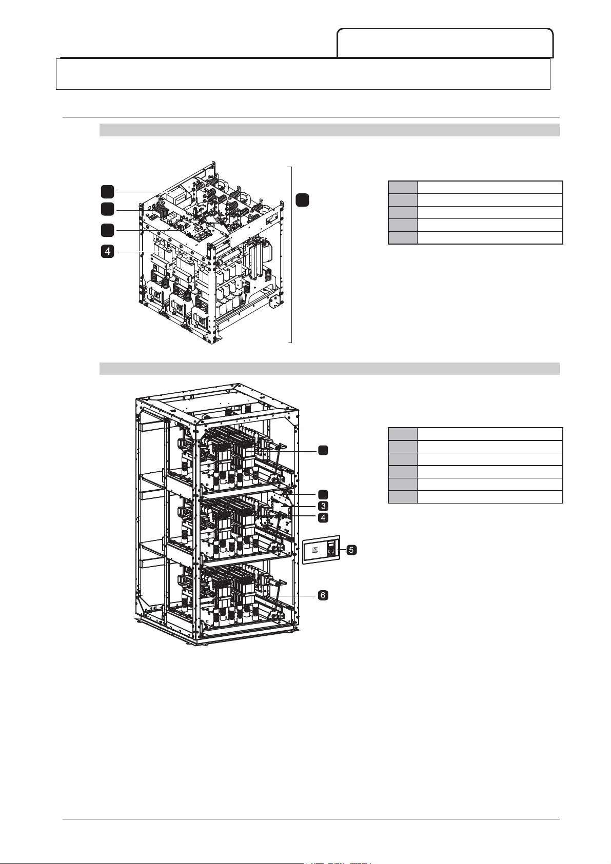
4.1 Key Components
Key Components (models V02 ~ V07)
SPECIFICATIONS
1
2
3
Key Components (model V13)
Control transformer
5
Control voltage terminal block
Power interface board
Phase arm (x3)
Power assembly
03993.D
Phase arm
1
Control voltage terminal block
Power interface board
Phase arm
Controller
2
Phase arm
07235.C
710-13937-00C MVS Panel User Manual 9
Page 11
SPECIFICATIONS
ABCabcdeWeight
(phase
arm)
Weight
(power
assembly)
NOTE
A
ABCabcdeWeight
(phase
arm)
Weight
(power
assembly)
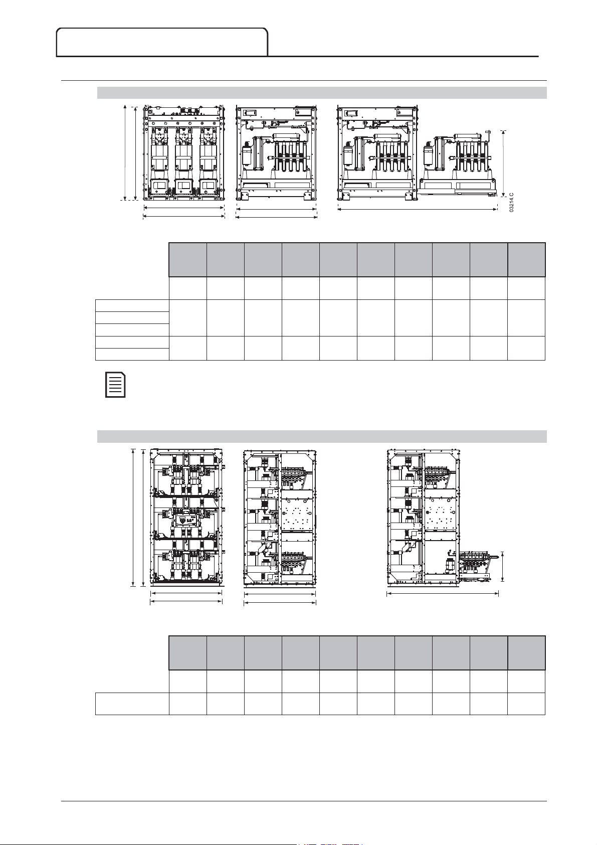
4.2 Dimensions and Weights
Models V02 ~ V07 (Power Assembly)
A
a
e
b
B
Front view Side view Phase arm extended
mm
(inch)mm(inch)mm(inch)mm(inch)mm(inch)mm(inch)mm(inch)mm(inch)
MVSxxxx-V02
MVSxxxx-V03
MVSxxxx-V04
MVSxxxx-V06
MVSxxxx-V07
772
(30.4)
832
(32.8)
669
(26.3)
875
(34.5)
For models MVSxxxxV02 to MVSxxxxV04, these dimensions apply up to 321 A. For the same models with
current ratings of 500 A, the MVSxxxxV06 dimensions apply.
Model V13 (Power Assembly)
667
(26.3)
817
(32.2)
c
C
750
(29.5)
810
(31.9)
658
(25.9)
864
(34.0)
650
(25.6)
800
(31.5)
d
1302
(51.3)
1559
(61.4)
kg
(lb)
531
(20.9)29(63.9)
551
(21.7)44(97)
kg
(lb)
165
(363.8)
217
(478.4)
a
e
07233.C
b
B
c
C
d
e
Front view Side view Phase arm extended
mm
(inch)mm(inch)mm(inch)mm(inch)mm(inch)mm(inch)mm(inch)mm(inch)
MVSxxxx-V13
2225
(87.6)
1300
(51.2)
1175
(46.3)
2200
( 86.6)
1150
(45.3)
1150
(45.3)
1785
(70.3)
510
(20.1)
kg
(lb)
127
(279.9)
kg
(lb)
720
(1587)
10 MVS Panel User Manual 710-13937-00C
Page 12
340.0
(13.39)
220.0 (8.66)
80
(3.14)
1
INPUTB
INPUTA
RESET
STOP
START
Run Trip LocalReady
Exit
Menu
Store
Logs
Alt
Tools
Rese t
LCL
RMT
StopStar t
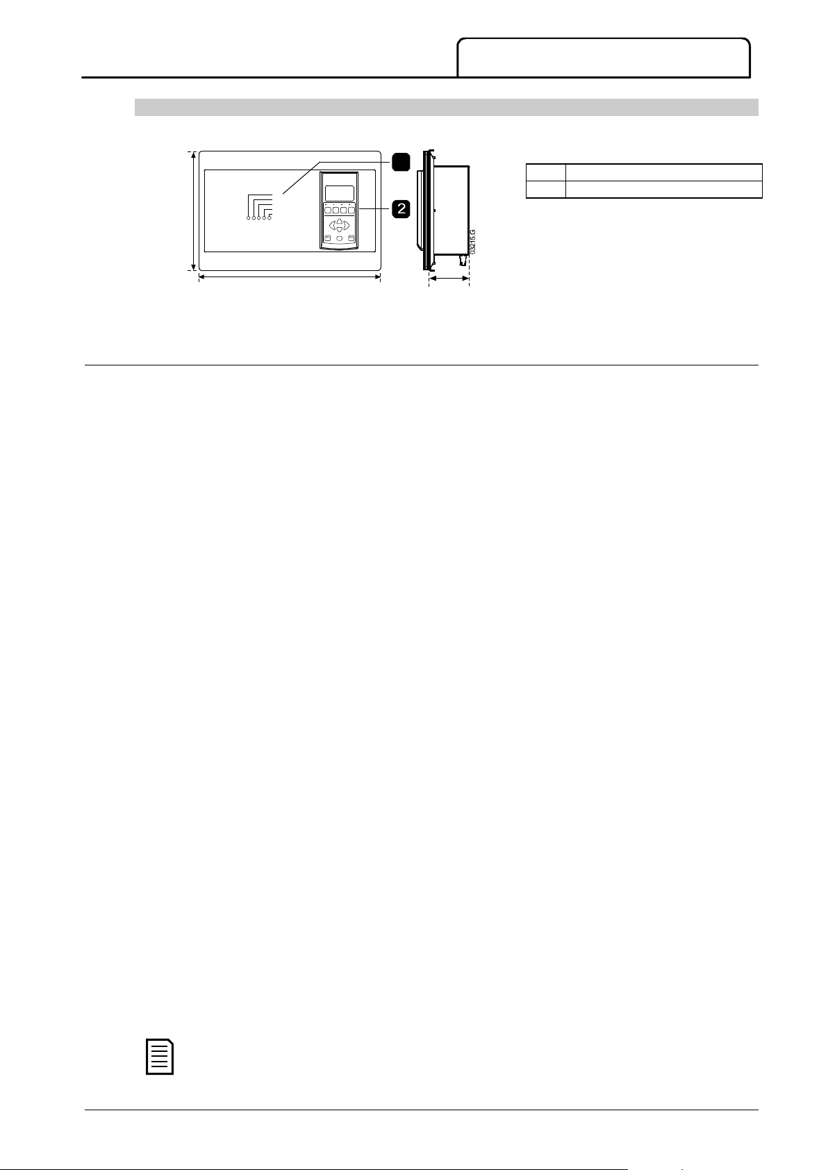
1 Control input LEDs
2
Keypad
Supply
Control Inputs
NOTE
SPECIFICATIONS
Controller
The controller is suitable for use with all MVS soft starters.
Dimensions are shown in mm (inch).
Weight: 2.1 kg (4.63 lb)
4.3 General Technical Data
Mains Voltage
MVSxxxxV02 ............................................................................................................................................................................ 2.3 kV Phase-phase
MVSxxxxV03 ............................................................................................................................................................................ 3.3 kV Phase-phase
MVSxxxxV04 ............................................................................................................................................................................ 4.2 kV Phase-phase
MVSxxxxV06 ............................................................................................................................................................................ 6.6 kV Phase-phase
MVSxxxxV07 ............................................................................................................................................................................ 7.2 kV Phase-phase
MVSxxxxV13 ......................................................................................................................................................................... 13.8 kV Phase-phase
Rated Frequency (fr) ............................................................................................................................................................................................ 50/60 Hz
Rated lightning impulse withstand voltage (U
MVSxxxxV02 ~ V04 .......................................................................................................................................................................................... 45 kV
MVSxxxxV06 ~ V07 .......................................................................................................................................................................................... 45 kV
MVSxxxxV13 .......................................................................................................................................................................................................... 85 kV
Rated power frequency withstand voltage (U
MVSxxxxV02 ~ V04 ...................................................................................................................................................................................... 11.5 kV
MVSxxxxV06 ~ V07 .......................................................................................................................................................................................... 20 kV
MVSxxxxV13 .......................................................................................................................................................................................................... 35 kV
Rated normal current (l
)
r
MVS0080-Vxx .......................................................................................................................................................................................................... 80 A
MVS0159-Vxx ....................................................................................................................................................................................................... 159 A
MVS0200-Vxx ....................................................................................................................................................................................................... 200 A
MVS0230-Vxx ....................................................................................................................................................................................................... 230 A
MVS0321-Vxx ....................................................................................................................................................................................................... 321 A
MVS0500-Vxx ....................................................................................................................................................................................................... 500 A
Rated short-time withstand current (symmetrical RMS) (l
MVSxxxxV02 ~ V07 ...................................................................................................................................................................................... 48 kA
MVSxxxxV13 ...................................................................................................................................................................................................... 75 kA
Form designation .................................................................................................................. Bypassed semiconductor motor starter form 1
Control voltage
MVSxxxxV02 ~ V07 .................................................................................................................................... 110 ~130 or 220 ~ 240 VAC
VSxxxxV13 ...................................................................................................................................................................................... 85 ~ 275 VAC
M
Rated Frequency ..................................................................................................................................................................................................... 50/60 Hz
Typical power consumption
MVSxxxxV02 ~ V07 ............................................................................................................................................................. 70 W continuous
MVSxxxxV13 .......................................................................................................................................................................... 100 W continuous
Start (C23, C24) ....................................................................................................................................................................... 24 VDC, 8 mA approx
Stop (C31, C32) ....................................................................................................................................................................... 24 VDC, 8 mA approx
Reset (C41, C42) ..................................................................................................................................................................... 24 VDC, 8 mA approx
Input A (C53, C54) ................................................................................................................................................................... 24 VDC, 8 mA approx
Input B (C63, C64) .................................................................................................................................................................. 24 VDC, 8 mA approx
Motor thermistor (B4, B5) ......................................................................................................................................................... Trip point > 2.4 kΩ
710-13937-00C MVS Panel User Manual 11
All control inputs are potential free. Do not apply external voltage to these inputs.
)
p
)
d
)
k
1
2
3
3
Page 13

SPECIFICATIONS
Outputs
Outputs on power interface board
Outputs on Controller
Characteristics
Environmental
EMC Emission
EMC Immunity
Standards Approvals
O
Main contactor (13, 14) ............................................................................................................................................................. Normally Open
Bypass contactor (23, 24) ......................................................................................................................................................... Normally Open
Run Output/ PFC (33, 34) ....................................................................................................................................................... Normally Open
Fan control output (43, 44) ..................................................................................................................................................... Normally Open
Output Relay A (43, 44) ........................................................................................................................................................... Normally Open
Output Relay B (51, 52, 54) ............................................................................................................................................................ Changeover
Output Relay C (61, 62, 64) ........................................................................................................................................................... Changeover
Analog output (B10, B11) ............................................................................................................................................ 0-20 mA or 4-20 mA
.............................................................................................................................................................................................. 10 A @ 250 VAC resistive
............................................................................................................................................................................................. 6 A @ 250 VAC 15 p.f. 0.3
................................................................................................................................................................................................. 10 A @ 30 VDC resistive
Degree of Protection
Power Assembly ...................................................................................................................................................................................................... IP00
Controller ........................................................................................................................................................................................... IP54/ NEMA 12
Operating temperature ....................................................................................................... - Ý&WR&ZLWKGHUDWLQJWR&
Humidity ................................................................................................................................................................ 5% to 95% Relative Humidity
Storage temperature ....................................................................................................................................................................... - Ý&WRÝ&
Humidity ................................................................................................................................................................ 5% to 95% Relative Humidity
Operating Altitude ............................................................................................................................ 0 - 1000 m, above 1000 m with derating
Pollution degree ................................................................................................................................................................................. Pollution Degree 3
Vibration ....................................................................................................................................................................................... Designed to IEC 60068
Equipment class (EMC) ........................................................................................................................................................................................... Class A
Conducted radio frequency emission ......................................................................................... 10 kHz to 150 kHz: < 120 - 69 dB μV
........................................................................................................................................................................... 0.15 MHz to 0.5 MHz: < 79 dB μV
............................................................................................................................................................................... 0.5 MHz to 30 MHz: < 73 dB μV
Radiated radio frequency emission ......................................................................................... 0.15 MHz to 30 MHz: < 80-50 dB μV/m
................................................................................................................................................................ 30 MHz to 100 MHz: < 60-54 dB μV/m
.................................................................................................................................................................. 100 MHz to 2000 MHz: < 54 dB μV/m
This product has been designed as Class A equipment. Use of this product in domestic environments may cause
radio interference, in which case the user may be required to employ additional mitigation methods.
Electrostatic Discharge ................................................................................................................. 6 kV contact discharge, 8 kV air discharge
Radio Frequency Electromagnetic Field ...................................................................................................... 80 MHz to 1000 MHz: 10 V/m
Fast Transients 5/50 ns (main and control circuits) ....................................................................... 2 kV line to earth, 1 kV line to line
Surges 1.2/50 μs (main and control circuits) ................................................................................... 2 kV line to earth, 1 kV line to line
Voltage dip and short time interruption (safe shutdown) .......................................................... 5000 ms (at 0% nominal voltage)
C ....................................................................................................................................................................................................... EMC requirements
CE ......................................................................................................................................................................................................... EMC EU Directive
1
Short circuit current, with appropriate R rated fuses fitted.
2
It is critical that the circuit breaker and associated protection relay are set to trip <150 ms. Failure to do so could
result in SCR rupture and subsequent arc fault.
3
Excludes contactors and/or circuit breakers.
12 MVS Panel User Manual 710-13937-00C
Page 14
4.4 Panel Specifications
NOTE
1
2
3
4
5
6
7
8
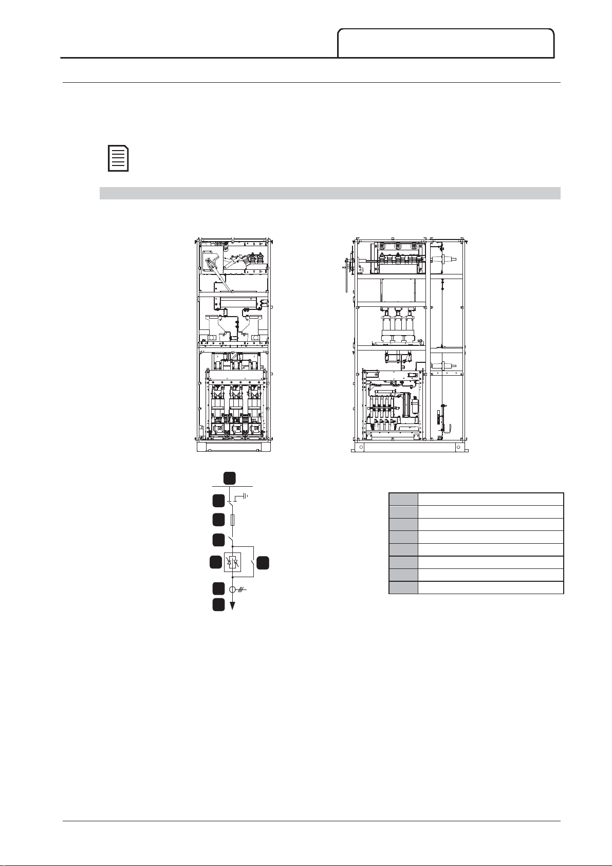
AuCom switchgear panels are categorised as follows:
Soft starter panel (SSP)
Standard panels
Panel layout views depict only typical panel configuration options.
Soft Starter Panel (SSP)
The soft starter panel is designed to house the primary soft starter components and associated switchgear.
SPECIFICATIONS
Typical Soft Starter Panel
14560.A
Front view Side view
1
2
Incoming supply
1
Isolator/Earth switch
3
4
R-Rated protection fuses
Main switching apparatus
2
Power assembly
5
7
Current transformer
Bypass switching apparatus
6
8
1
Cables (top or bottom entry) or horizontal busbar system. Cables and busbars are not supplied with the standard
14079.B
Cables to motor
3
product, but AuCom can supply a horizontal busbar system on request.
2
Contactor (a circuit breaker may be fitted instead, on request). Installations with a circuit breaker do not require
R-rated protection fuses.
3
Outgoing motor cables (top or bottom exit).
2
710-13937-00C MVS Panel User Manual 13
Page 15
SPECIFICATIONS
1
2
3
4
5
Standard Panels
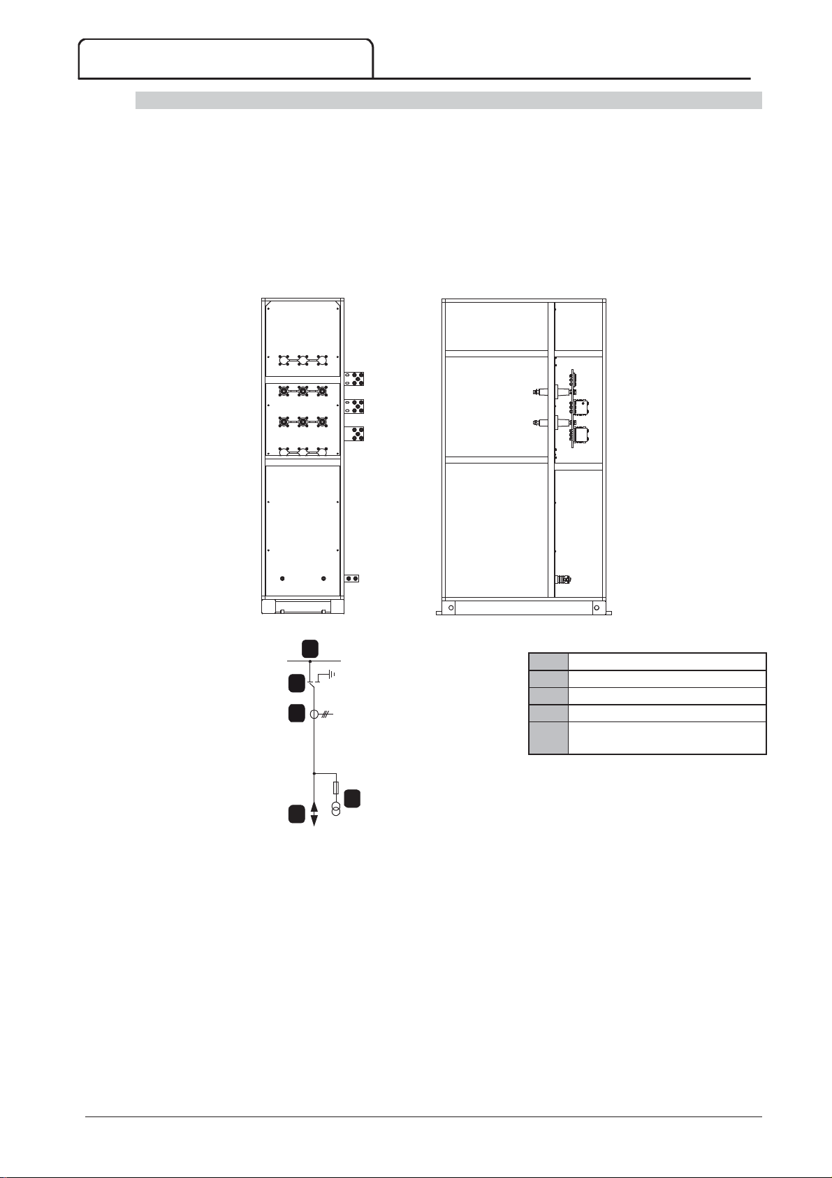
AuCom standard panels are designed to be installed individually or connected to an AuCom soft starter panel (SSP)
in a panel line-up. Standard panels may be equipped with customisable switchgear options and are available as
follows:
Transition panel (TRP)
Power factor correction panel (PFP)
Transition Panel (TRP)
Transition panels are used to connect cables or busbars between two different panels in a line-up. A transition panel
may also be used to connect cables from one panel to busbars in another.
Typical Transition Panel
Front view Side view
1
2
3
4
5
14080.A
12960.A
Horizontal busbar system
Isolator/Earth switch (optional)
Current transformer (optional)
Voltage transformer (optional)
Incoming supply cables or busbar
system (customer)
14 MVS Panel User Manual 710-13937-00C
Page 16
SPECIFICATIONS
1
2
3
4
5
6
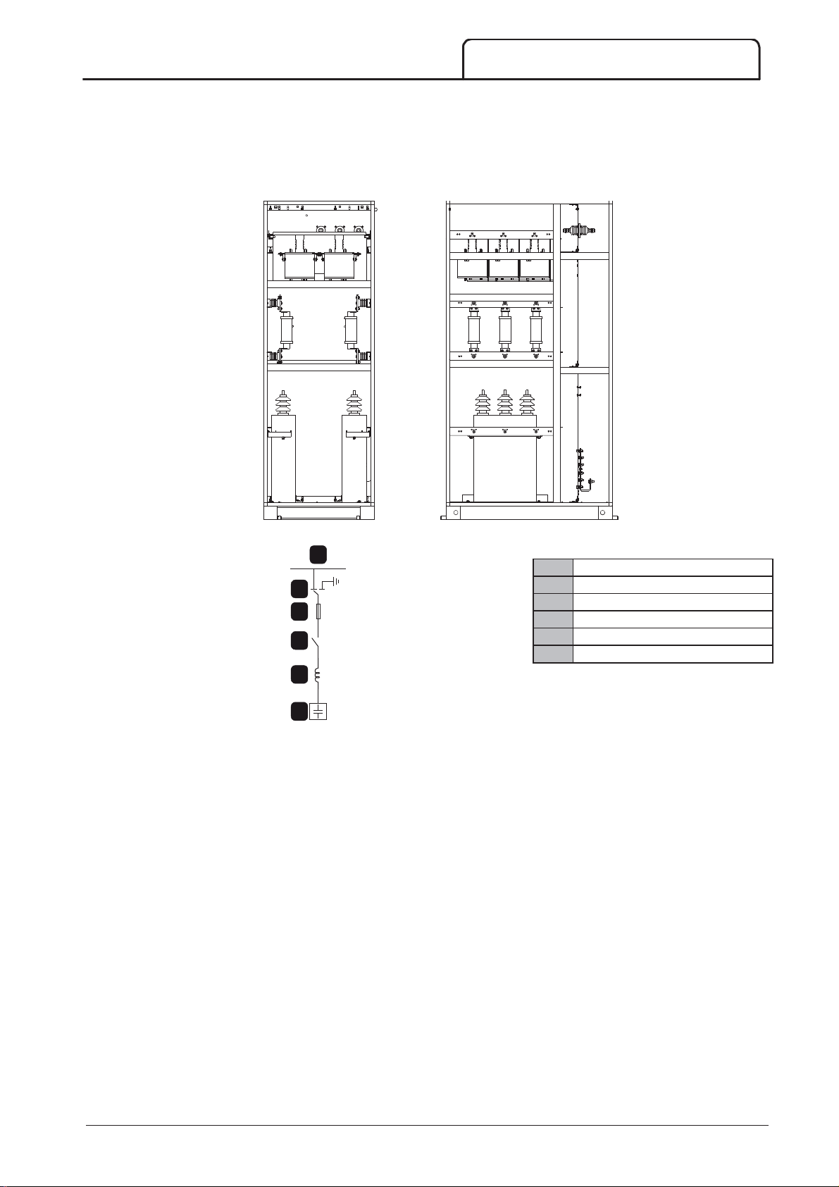
Power Factor Correction Panel (PFP)
A power factor correction panel consists of capacitor banks which are switched by means of a contactor. This
contactor is controlled by the soft starter or power factor controller, which measures power factor in an electrical
network.
Typical Power Factor Correction Panel
14123.A
Front view Side view
1
Incoming supply
2
3
4
Isolator/Earth switch
E-rated protection fuses
Line contactor
Inrush reactors (3x single phase)
1
2
2
2
PFC capacitor bank (3-phase)
5
6
1
Cables (top or bottom entry) or horizontal busbar system. Cables and busbars are not supplied with the standard
14081.A
product, but AuCom can supply a horizontal busbar system on request.
2
Not required when incoming supply is fed from the soft starter panel (SSP).
710-13937-00C MVS Panel User Manual 15
Page 17
RECEIVING AND STORAGE
NOTE
NOTE
5 Receiving and Storage
All AuCom panels are individually packed and securely braced for shipment. Depending on the size and weight, it
may be necessary to ship the equipment in several sections to facilitate handling.
Panels may include relatively delicate equipment. Handle all sections with care when unloading. Some electrical
components may be shipped separately and then installed on-site. The shipping inventory should account for all
individual components.
5.1 Receiving
Inspect equipment as soon as possible for any damage that may have occurred during transit. Before accepting
delivery, examine packaging for any signs of damage. A damaged package may indicate that the panel and internal
components may also be damaged.
Check that the shipping manifest accounts for all equipment delivered. Any missing or damaged equipment should
be noted on the freight bill and the carrier notified immediately. A record of the missing or damaged equipment
should also be sent to AuCom.
Avoid using heavy or sharp-edged tools while unpacking, as these may damage the equipment. Use nail
pliers to separate all four sides of the wooden packaging box.
5.2 Storage
If immediate installation is not possible, the equipment should be stored in its original packaging in a clean and dry
area indoors. Always store panels upright on their wooden pallets to keep them off the floor and allow air to pass
under it freely.
Equipment can be stored for a maximum of 12 months from the date of packaging as the quality of the
packaging material degrades over time.
The following storage conditions should be met (IEC 60721-3-1, classification 1K3):
Temperature -5 °C ~ 40 °C
Relative humidity 50 ~ 95%
Rate of change of temperature 0.5 °C/min
The following general precautions should be followed when storing equipment indoors:
Do not unpack the panel or other components until they are ready for installation.
If electrical components such as circuit breakers are to be stored for more than three months in humid
conditions, space heaters should be used in the storage area to limit condensation. Switchgear panels with
in-built anti-condensation heaters may be powered from an external supply during storage.
Rats and other vermin may cause considerable damage and periodic inspection is necessary to minimise
the danger they pose.
Ensure the floor of the storage area is smooth and level to prevent mechanical strain to the structure and
components.
16 MVS Panel User Manual 710-13937-00C
Page 18
NOTE
6 Installation
Site installation of panels should only be carried out by specially trained and skilled personnel. The location must be
adequately prepared with wall openings, ventilation ducts and cabling connections to the power supply.
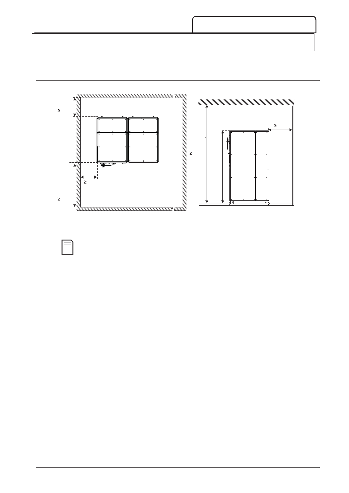
6.1 Clearance Requirements
While installing AuCom switchgear panels, ensure that minimum clearance requirements are met.
600
600
2800
INSTALLATION
600
2322
1200
14091.A
Plan view Side view
Standard panels may be mounted closer to the wall from the rear if required. Consult AuCom if closer
wall mounting is required.
710-13937-00C MVS Panel User Manual 17
Page 19
INSTALLATION
NOTE
1
2
3
NOTE
6.2 Foundation Requirements
The maximum tolerance for switchroom floor is ± 2 mm per metre (with a maximum of ± 5 mm over
the entire panel line-up). Failure to comply with these recommendations may impair the
electro-mechanical functionality of some components and the structural integrity of the entire panel
system.
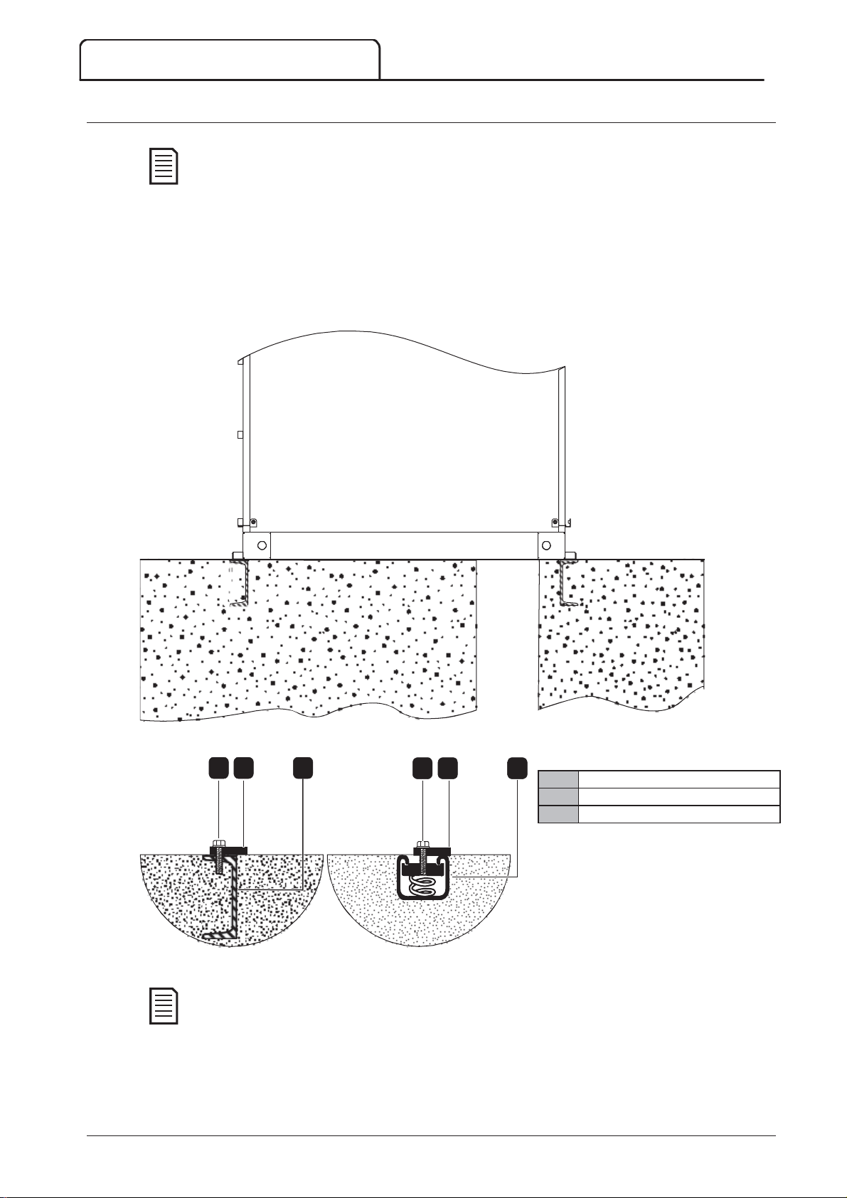
The base of the panels is suitable for mounting directly to the switchroom floor. It is recommended that buried steel
channels are installed in a level concrete floor to support the equipment. The surfaces of the buried steel channels
should be level with the finished floor and aligned with each other prior to final anchoring. The panel’s base should
be evenly supported by the concrete floor. If the panel is raised above the floor level by the mounting channels, the
entire base frame must be supported at the same level. If the panel is part of a line-up, all channels must be level
and aligned with each other.
The figure below illustrates typical methods for anchoring panels to buried steel channels.
1 2
Beam-type channel C-type channel
Anchor bolts, channels, and other materials are not supplied as part of the switchgear arrangement.
3
1 2 3
Anchor bolt
Panel connection
Buried steel channel
14083.A
14082.B
18 MVS Panel User Manual 710-13937-00C
Page 20
6.3 Fastening Panels to the Foundation
1
Width
mm (inch)
Depth
mm (inch)
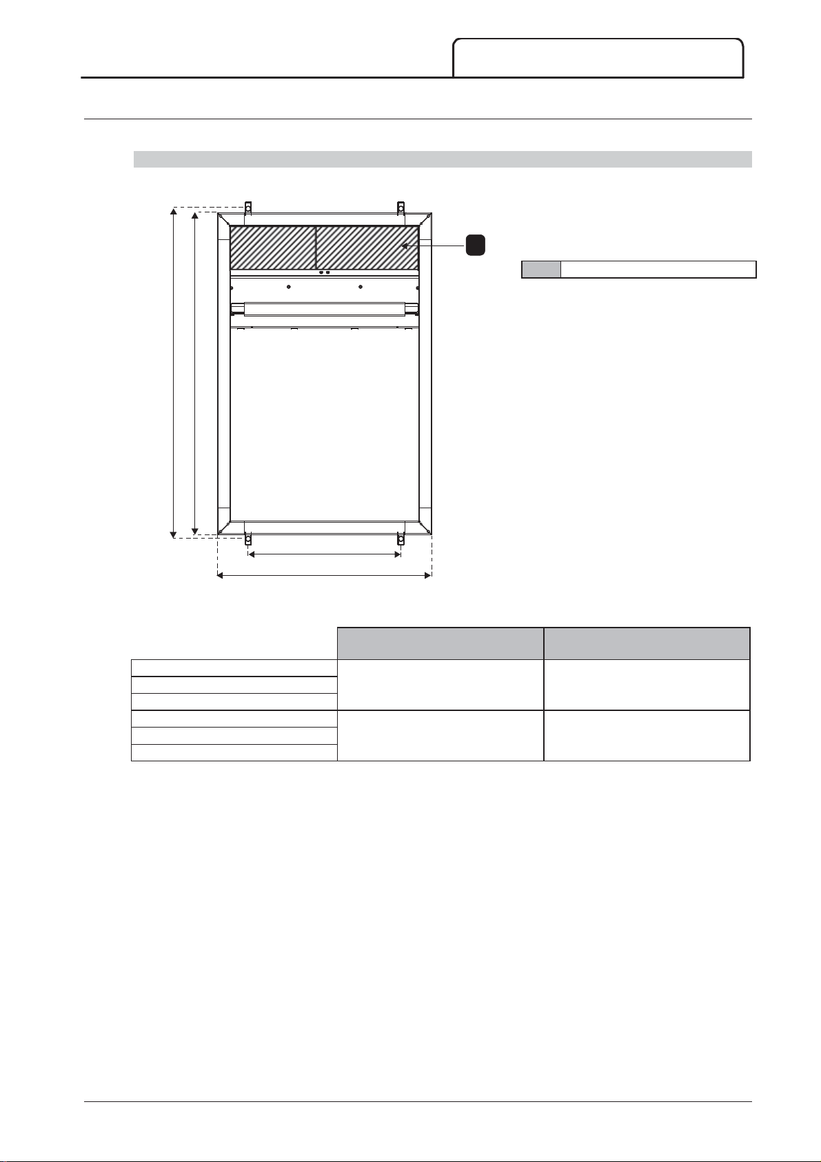
Switchgear panels must be fastened securely to a level floor which has been adequately prepared.
Soft Starter Panel (SSP)
It is recommended that all four bolt holes are used to securely bolt the panel to the floor using 10mm (0.39in) bolts.
1200
1230
INSTALLATION
1
Removable non-ferrous gland plate
570
800
14096.A
Plan view
MVSxxxx-V02
MVSxxxx-V03 800 (31.5) 1200 (47.2)
MVSxxxx-V04
MVSxxxx-V06
MVSxxxx-V07 1000 (39.3) 1200 (47.2)
MVSxxxx-V13
710-13937-00C MVS Panel User Manual 19
Page 21
INSTALLATION
1
Width
mm (inch)
Depth
mm (inch)
Standard Panels
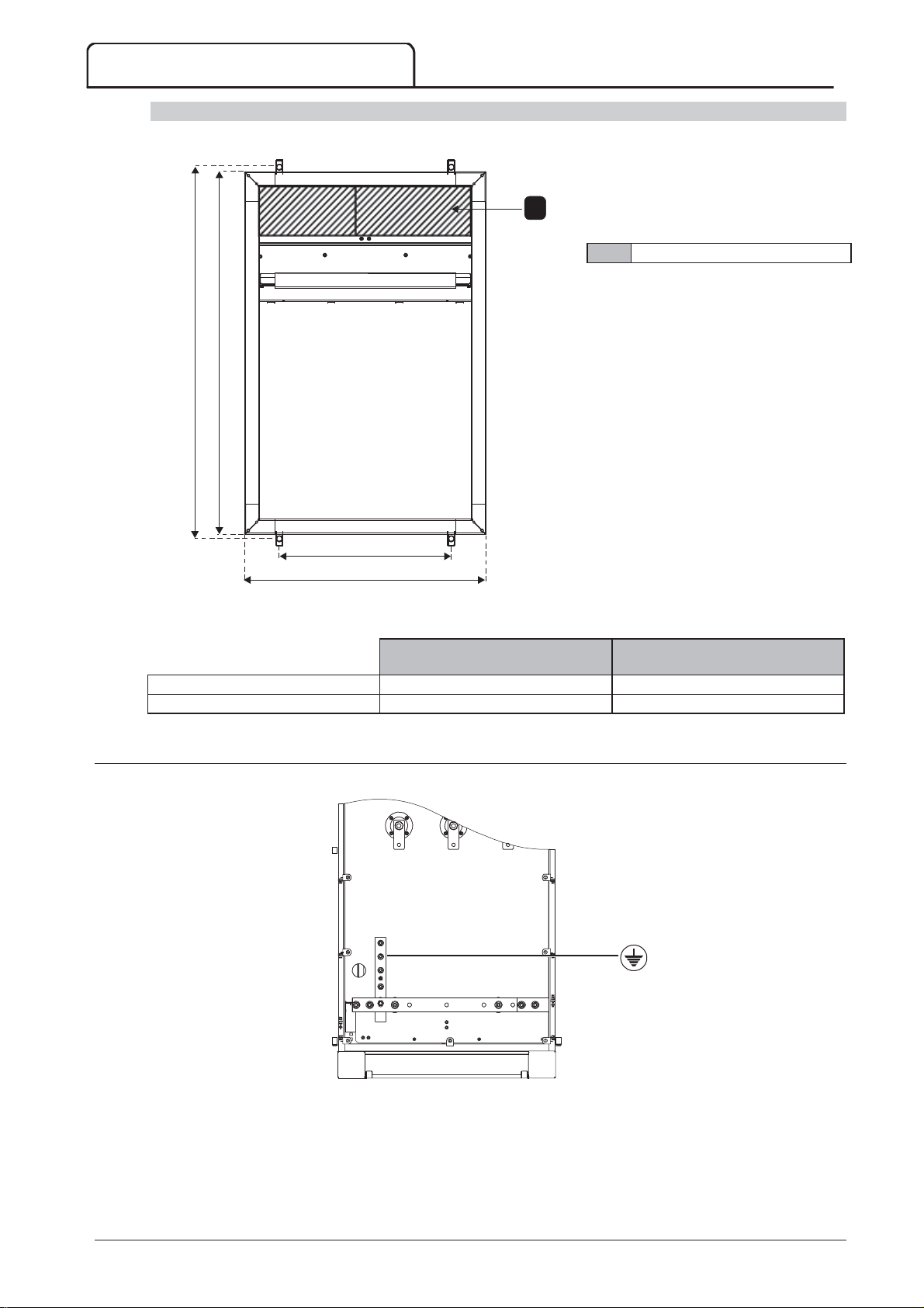
It is recommended that all four bolt holes are used to securely bolt the panel to the floor using 10mm (0.39in) bolts.
1230
1
Removable non-ferrous gland plate
1200
Transition Panel (TRP) 600 (23.6) 1200 (47.2)
Power Factor Panel (PFP) 800/1000 (31.5/39.2) 1200 (47.2)
6.4 Earth Termination
An earth bar is located at the rear of the panel.
427
600
Plan view
14096.A
14086.A
An earthing wire may be terminated anywhere along this bar using M10 high tensile grade 8.8 threaded fasteners for
all terminations.
20 MVS Panel User Manual 710-13937-00C
Page 22
6.5 Assembling the Switchgear Line-up
NOTE
1
2
NOTE
Switchgear panels may be connected together to form a panel line-up. Assembling the panel line-up includes the
following operations:
Aligning the panels
Fastening the panels together
Connecting the earth bus
Lifting and Moving
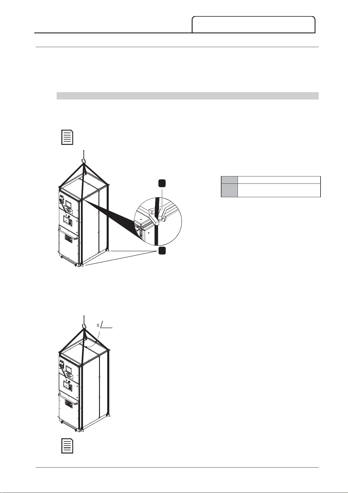
Panels can be moved in a number of ways. However, care should be taken to protect the panel sections or
enclosed electrical components from damage during moving. Provision has been made along the base of the panel
to fit lifting rods. Lifting cables can then be fitted for lifting with a crane.
The recommended method of moving the panel is using a crane. If height constraints prevent the use of
a crane, a forklift or jack may be used before removal of the wooden pallet.
INSTALLATION
1
Spreader bar
Lifting rods fitted through lifting
holes in base frame
14084.A
2
1. Locate the four lifting holes in the base frame of the panel.
2. Pass lifting rods through the lifting holes from one side of the panel to the other. Use lifting rods which are
approximately 30mm in diameter to ensure that rods are of sufficient tensile strength to bear the weight of the
panel.
3. Loop lifting cables around the ends of the lifting rods on both sides of the panel.
4. Fit spreader bars to the lifting cables at the top of the panel. The lifting cables must have spreaders from
front-to-rear and side-to-side to prevent twisting the lifting cables during transportation.
Before moving the panel:
60°
Ensure that the crane is tall enough that the angle formed between the
arms of the sling is no more than 60° when viewed from the front or rear
of the panel.
Always use lifting equipment that is rated for the prescribed load. Only
use a crane of sufficient lifting capacity to bear the weight of the
equipment to be lifted.
Identify the centre of gravity, physical dimensions, weight etc.
Plan the path along which the switchgear will be moved, ensuring that it is
free from obstructions.
If moving more than one unit at a time, disconnect bus connections
between panels to prevent damage to the busbars.
Ensure that adequate precautions have been taken to protect personnel
before moving the panel.
Only use AuCom recommended bolts and metal connectors. Never
replace or modify a manufactured lifting component.
14085.A
Spreader bar, lifting rods, and other materials are not supplied as part of the switchgear arrangement.
710-13937-00C MVS Panel User Manual 21
Page 23
INSTALLATION
1
2
3
Aligning the panels
Switchgear sections may be shipped individually to facilitate loading and transportation. At the installation site, the
shipping sections must be securely bolted together to form the switchgear line-up. Align the shipping sections side
by side on the foundation as follows:
Remove all packaging material from the first switchgear section to be installed, except the wooden pallet
on which each panel is mounted. The wooden pallet protects the switchgear and reduces risk of damage
during moving.
Move the panel to the desired location (refer to
bolts and discard the wooden pallet.
Line up the bolt holes in the base frame of the switchgear with the holes in the foundation steel channels
(refer to
Once the individual panels have been placed in position, use a level or plumb line to make sure the panel
line-up is level both across its depth and along its length. Draw an installation baseline the entire length of
the complete switchgear.
Install the other switchgear sections following the above steps, with reference to the installation base line.
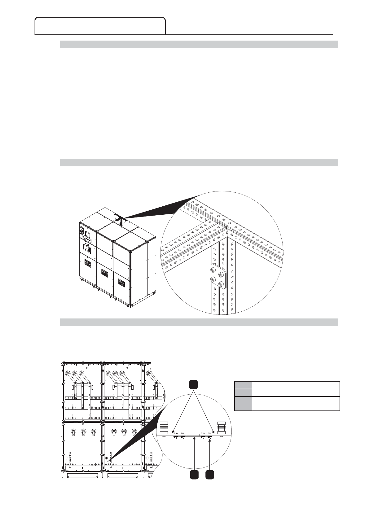
Fastening the panels together
Once the sections of the switchgear line-up have been aligned exactly, fasten adjacent panels together securely.
Use M6x10 screws to fasten panels together using the joining brackets supplied.
Fastening Panels to the Foundation
Lifting and Moving
for details).
on page 21 for details). Remove the
14097.A
Connecting the earth bus
The standard earth bus runs the entire length of the switchgear line-up. The earth bus in the switchgear line-up is
assembled in sections, with a bus joint in each panel. Terminals are provided on each joint for connecting the earth
bus to the earthing system of the switchgear building. Each panel is equipped with the facility to connect to the
building earth (refer to
Earth Termination
on page 20 for more information).
1
2 3
14117.A
Earth bus (30x5 mm)
Fish plate
M12x40 screws with Belleville
washers
22 MVS Panel User Manual 710-13937-00C
Page 24
INSTALLATION
NOTE
NOTE
NOTE
To connect the earth bus between panels in a line-up:
1. Slip the fish plate through the aperture in the panel.
2. Align the bolt holes of the fish plate with those in the bus joint of each panel and fasten together securely.
The MVS soft starter should only be installed in a restricted access location suitable for electrical equipment.
Ensure that the equipment room is clean and relatively duststarter. In particular, beware of concrete dust as it may cause corrosion.
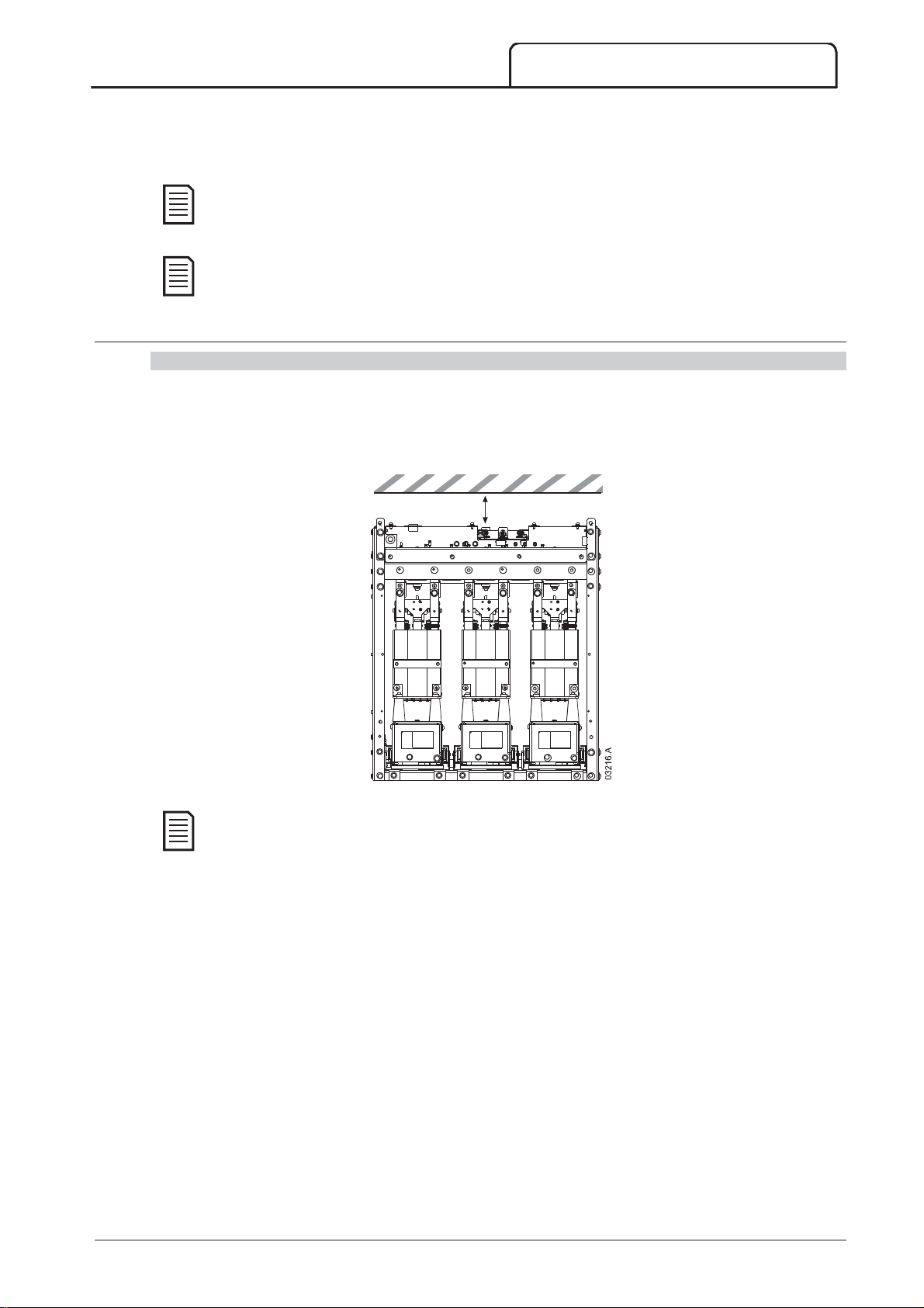
6.6 Mounting Instructions - Power Assembly
Clearances
The MVS power assembly is rated IP00 and must be installed inside an enclosure.
No clearance is required below or at the sides. For models V02 ~ V07, the power assembly should be installed
with 100 mm clearance above for isolation. Model V13 requires no additional clearance beyond the external
frame.
free before unpacking and installing the MVS soft
min 100 mm (3.93 inch)
Models with current ratings 500 A and above require forced air ventilation when installed in an
enclosure.
710-13937-00C MVS Panel User Manual 23
Page 25
INSTALLATION
1
2
3
A
mm (inch)
B
mm (inch)
C
mm (inch)
NOTE
Mounting Points
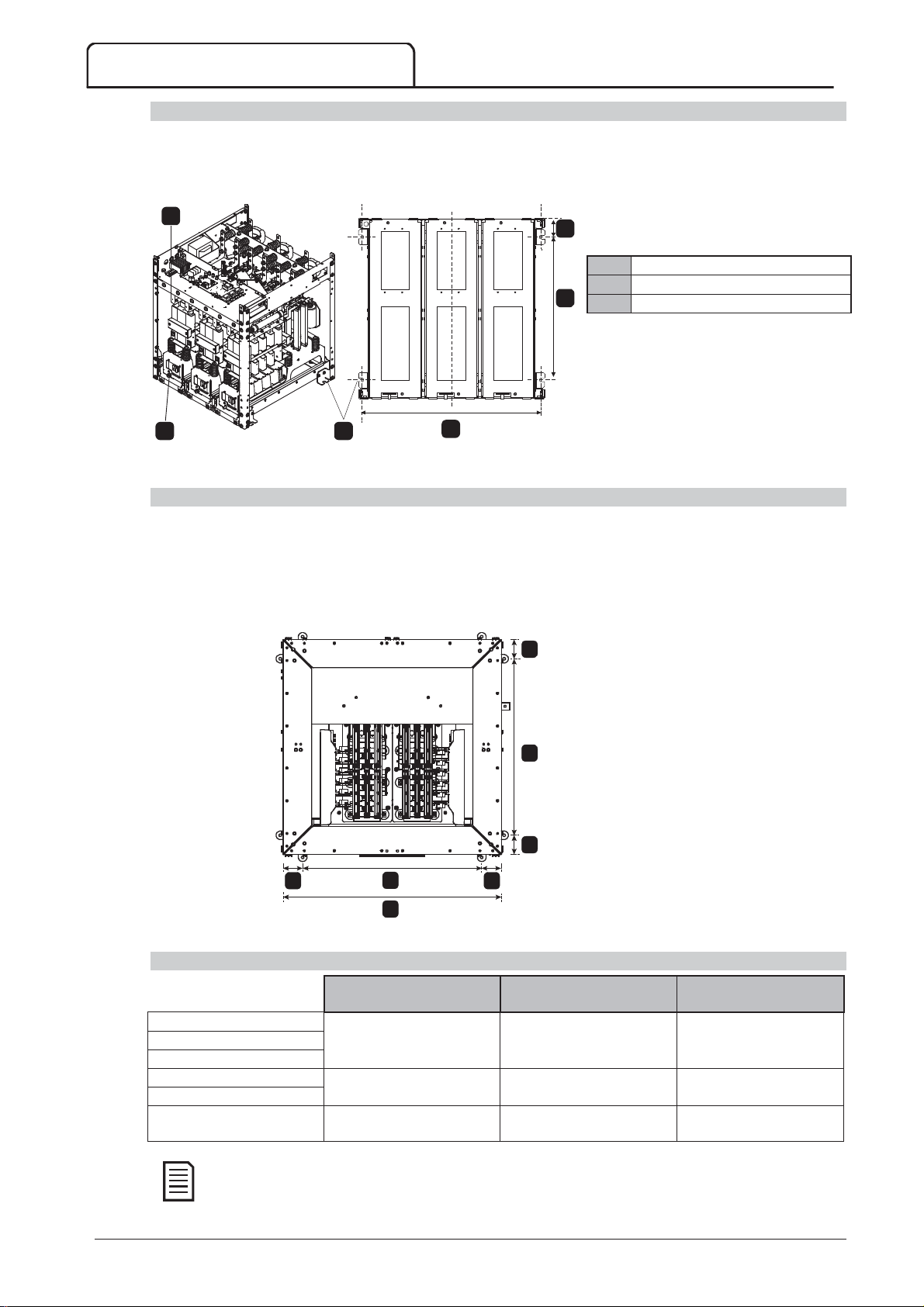
The power assembly is mounted in place using four M12 bolts. One bolt is required through each corner at the
base of the unit, tightened to a torque of 40 Nm. Individual phase arms are secured within the frame using one
M10 nut and two M10 high tensile grade 8.8 bolts complete with Belleville washers, all tightened to a torque of
28 ~ 30 Nm.
1
C
M10 bolts with belleville washers
M10 nut
2 3
B
A
10130.C
M12 mounting holes
Plan view
Front of unit
Mounting Points (model V13)
For V13 models, the power assembly is mounted in place using eight M12 bolts (two bolts per side at 944 mm
centres). Individual phase arms are secured within the frame using two locking rods and two lock nuts, tightened to
a torque of 10 Nm.
MVS model V13 comes with a travel plinth. For installation the frame should be bolted into a panel with eight M12
bolts, tightened to a torque of 28 ~ 30 Nm.
Plan view
C
07236.B
C C
B
A
Front of unit
Measurements
MVSxxxxV02 636
MVSxxxxV03
MVSxxxxV04
MVSxxxxV06 842
MVSxxxxV07
MVSxxxxV13
For models MVSxxxxV02 to MVSxxxxV04, these dimensions apply up to 321 A. For the same models with
current ratings of 500 A, the MVSxxxxV06 dimensions apply.
(25.04)
(33.15)
1150
(45.28)
B
C
513
(20.20)
663
(26.10)
944
(37.17)
68.5
(2.70)
68.5
(2.70)
103
(4.06)
24 MVS Panel User Manual 710-13937-00C
Page 26
6.7 Mounting Instructions - Controller
NOTE
1
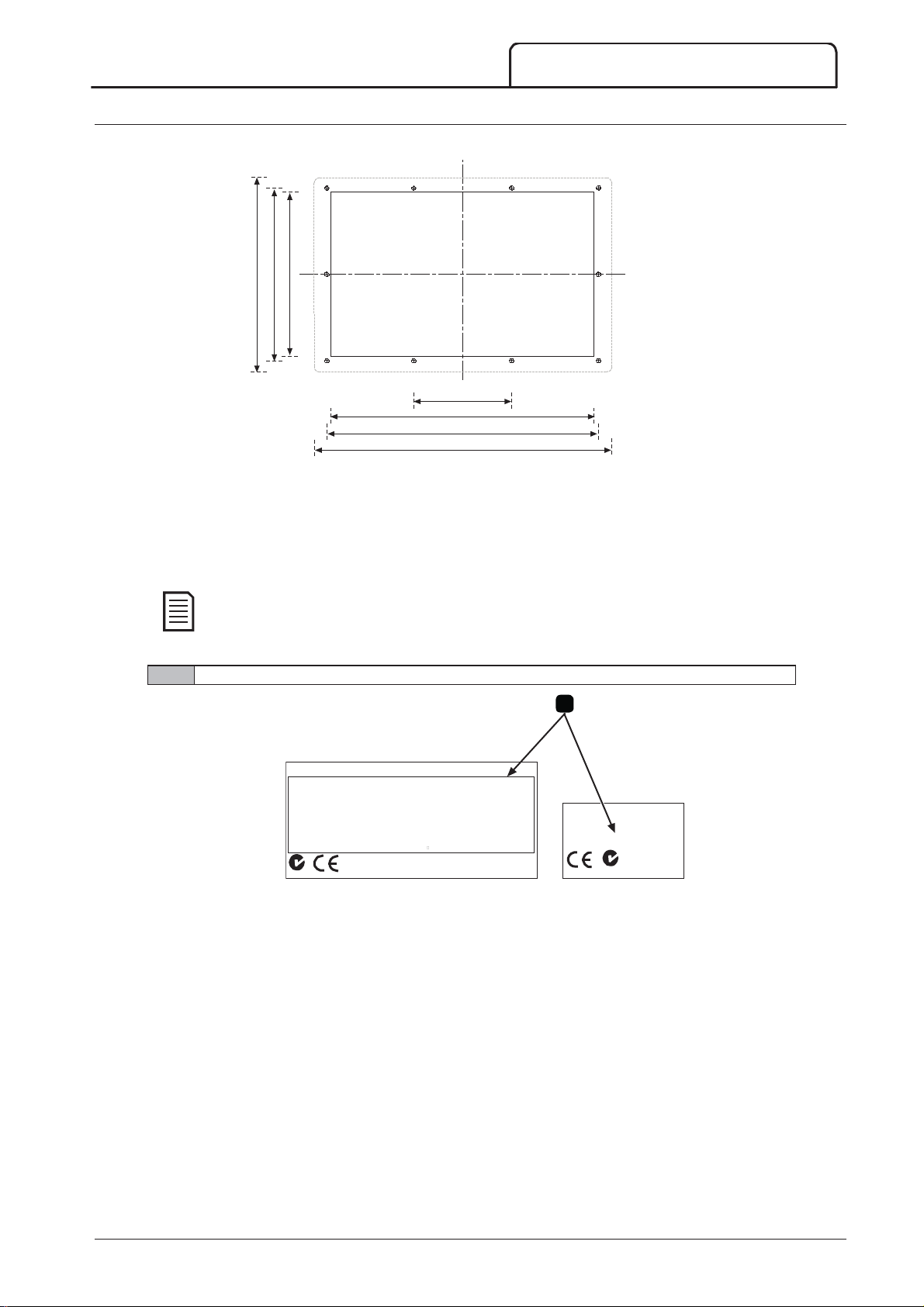
The controller is secured into place using ten M4 nuts, affixed to the studs on the back of the controller.
220 (8.66)
196 (7.72)
186 (7.32)
To mount the controller, make a 186 mm x 300 mm cutout at the desired mounting location. Ensure adequate
clearance (>85 mm) is available behind the mounting location. If you intend to use a communication module, allow
for a minimum clearance of 120 mm behind the mounting panel.
Drill 5 mm holes to accommodate the studs on the controller. Fit the MVS Controller through the cutout and
tighten the nuts onto the studs.
112 (4.41)
300 (11.81)
310 (12.20)
340 (13.39)
INSTALLATION
11073.A
Before installation, always ensure that you are using the correct controller for the soft starter. This can be
checked by comparing the serial number on the back of the controller with the serial number on the front
of the power assembly.
Serial number
1
MVS 0159-410
3-phase,
4.16kV AC, 50/60 Hz
S/C withstand:
Withstand Voltage:
Enclosur e r at ing:
Aux. terminals:
Aux. contacts:
Power terminals:
IEC 60047-4-2
Z79
Type 1 coordin ation, HR C fuses at prospective 48k A RMS
45000 VAC Cat II I
IP00, U L Open Type Pollution Degree 3
#24-#14 AWG, 0.2-2.5 mm2 (0.5 Nm, 4.5 l b- in)
10 A @ 250 V AC DF 10%, A300, AC-15 6 A @ 250 V AC
150mm2 at torque 28-30 Nm, 20-22 ft-lb
Copper or stranded 75
S/N: 822805-074
159A : AC53b 4-20: 1780, 1.16M VA
C conductors
Made in New Zealand
MAIN CONTROL M ODUL E
MVS-0159-410-V04-C12
S/N: 822805-074
T. E Q.
IN D. CON
32 AN
Z79
03530.F
710-13937-00C MVS Panel User Manual 25
Page 27
INSTALLATION
A
ABCDEFGHI
J
NOTE
6.8 Power Terminations
Models V02 ~ V07
T1B
T1
L1
T2B, T2, L2
T3B, T3, L3
13
(0.51)
25
(0.98)
6
(0.24)
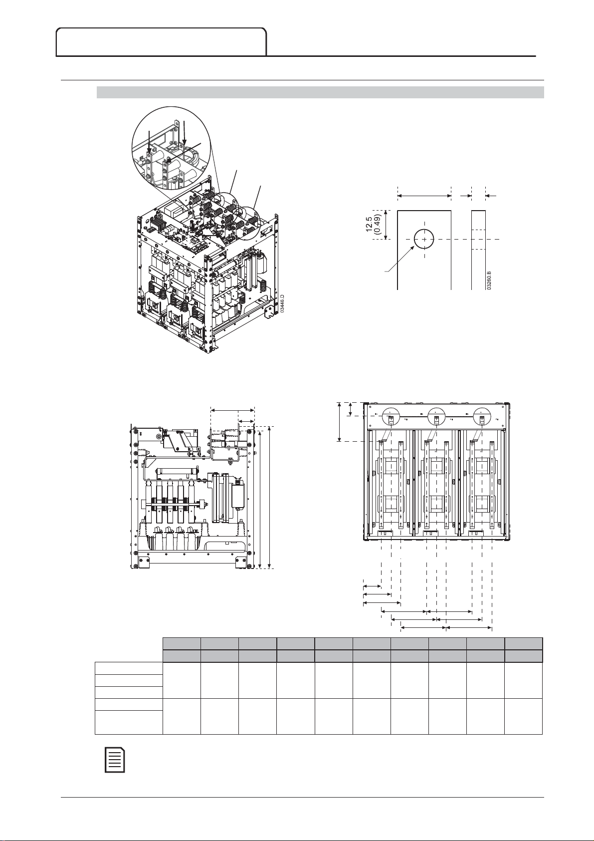
Use only M10 high tensile grade 8.8 threaded fasteners for all terminations. Use a pre-load torque setting between
28 ~ 30 Nm. Use only Belleville washers.
Side view Top view
A
B
B
CD
10131.B
L3L2L1 T3BT2BT1B
03217.D
mm (inch) mm (inch) mm (inch) mm (inch) mm (inch) mm (inch) mm (inch) mm (inch) mm (inch) mm (inch)
MVSxxxxV02*
MVSxxxxV03*
MVSxxxxV04*
MVSxxxxV06
MVSxxxxV07
228
(8.98)79(3.11)
228
(8.98)79(3.11)
744
(29.29)
792
(31.18)
760
(29.92)79(3.11)
806
(31.73)
107
(4.19)
E
F
129
(5.08)
164
(6.46)
T1
G
(7.05)
(8.72)
T2
H
I
JJ
179
200
(7.87)
222
268
(10.55)
T3
H
I
200
(7.87)
268
(10.55)
200
(7.87)
268
(10.55)
For models MVSxxxxV02 to MVSxxxxV04, these dimensions apply up to 321 A. For the same models with
current ratings of 500 A, the MVSxxxxV06 dimensions apply.
26 MVS Panel User Manual 710-13937-00C
Page 28
Model V13
abcdefghi
07237.B
T1B
T1
L1
T2B
T2
L2
T3B
T3
L3
INSTALLATION
Busbar termination detail
c
MVSxxxx-V13
d
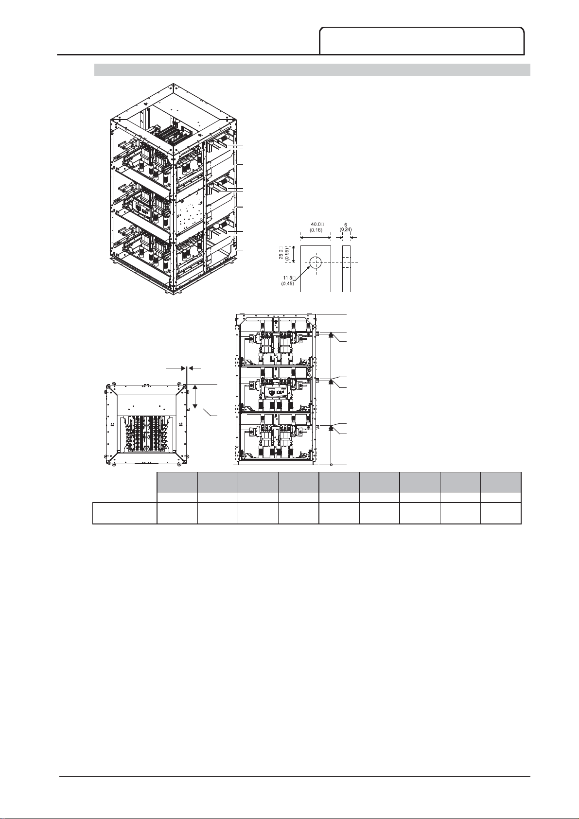
Use only M10 high tensile grade 8.8
e
threaded fasteners for all terminations.
Use a pre-load torque setting between
a
0.0
b
07238.B
mm (inch) mm (inch) mm (inch) mm (inch) mm (inch) mm (inch) mm (inch) mm (inch) mm (inch)
19.8
(0.78)
355.0
(13.98)
2200
(86.6)
1965.5
(77.4)
1936.5
(76.2)
28 ~ 30 Nm. Use only Belleville
washers.
f
g
h
i
0.0
1274.8
(50.2)
1245.8
(49.0)
584.1
(23.0)
555.1
(21.9)
710-13937-00C MVS Panel User Manual 27
Page 29
INSTALLATION
A
(mm)
B
(mm2)
C
(mm)
1
2
3
A
B
C
CAUTION
6.9 Earth Terminations
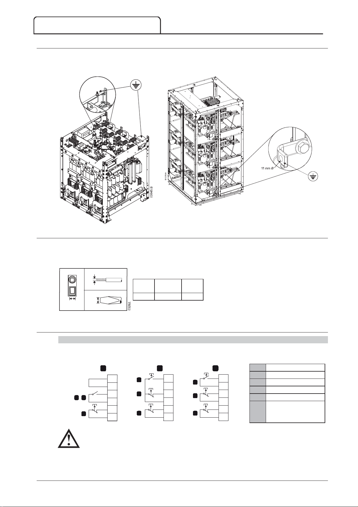
A 10 mm earth stud is located on each side of the power assembly, at the rear of the unit. Use only M10 high
tensile grade 8.8 threaded fasteners for all terminations. Use a pre-load torque setting between 28 ~ 30 Nm.
Use only Belleville washers.
6.10 Control Terminations
On the control voltage terminal block, control wiring is secured in place by 3 mm spring terminals. Use a
screwdriver to open the terminal clamp, then insert the wire into the terminal cage. Release the clamp by
removing the screwdriver.
B
(
32.53
A
C
C
(
6.11 Wiring Terminations on the Controller
Control Wiring
The MVS has three fixed inputs for remote control. These inputs should be controlled by contacts rated for low
voltage, low current operation (gold flash or similar).
1
C23
C24
A
B
C
C31
C32
C41
C42
A
B
C
2
C23
C24
C31
C32
C41
C42
(
3
A
B
C
C23
C24
C31
C32
C41
C42
03943.D
Two-wire control
Three-wire control
Four-wire control
Start
Stop
Reset
Do not apply voltage to the control input terminals. These are active 24 VDC inputs and must be
controlled with potential free contacts.
Cables to the control inputs must be segregated from mains voltage and motor cabling.
The reset input can be normally open or normally closed. Use parameter 6M to select the configuration.
28 MVS Panel User Manual 710-13937-00C
Page 30
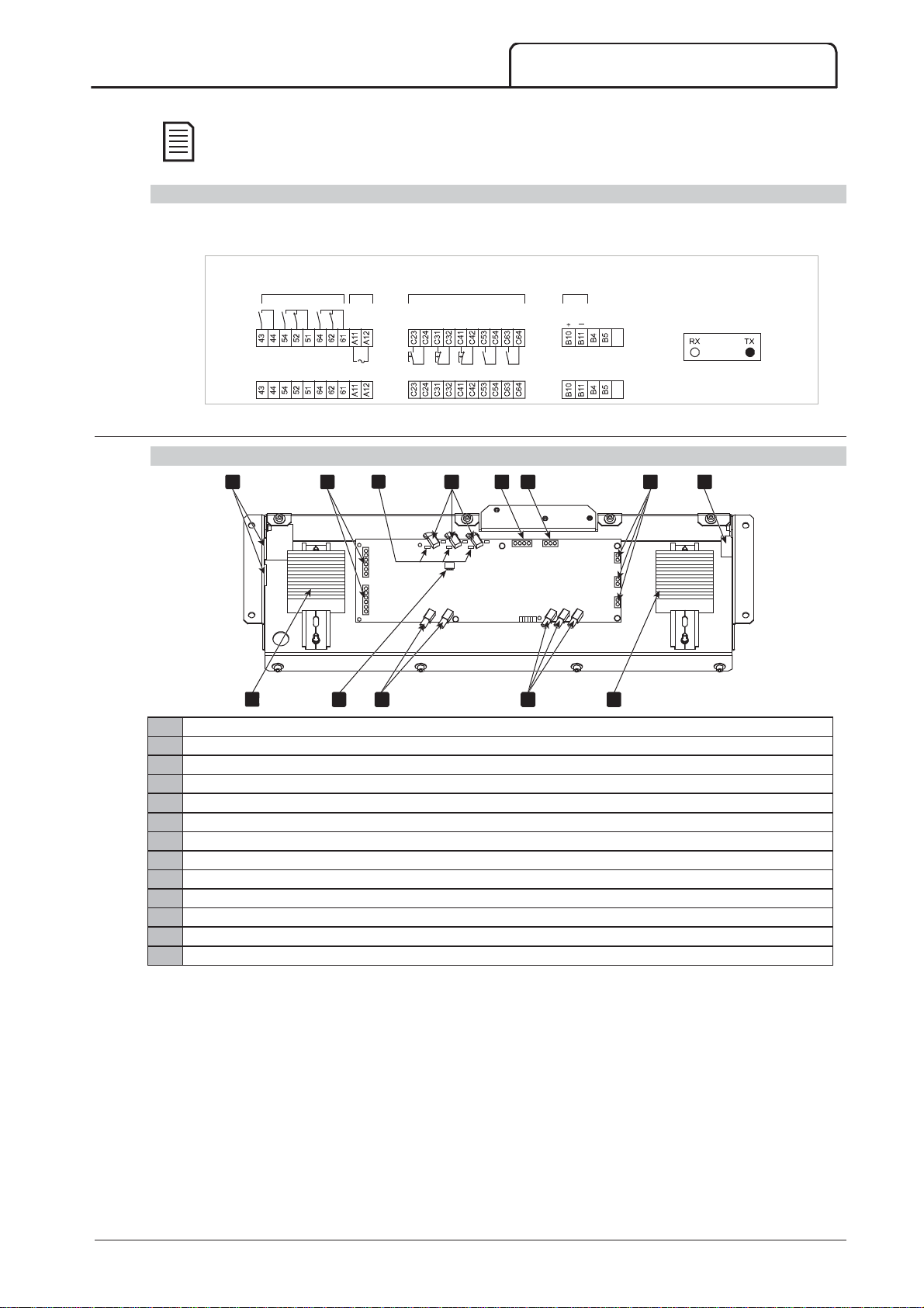
NOTE
Reset input is normally closed by default.
1
2
3
4
5
6
7
8
9
10
11
12
13
Terminal Block (controller)
Terminations on the controller use plug-in terminals. Unplug the terminal blocks, complete the wiring, then re-plug
the terminal blocks into the controller.
Analo
Out
Output A
lay Outputs
Re
Output B
Control
Supply
/DC
24 VAC
Output C
Control Inputs
Start
Stop
Reset
ProgA
Prog B
6.12 Wiring Terminations on the Power Interface Board
Models V02 ~ V07
1 4
2
3
5 6
INSTALLATION
g
put
on
Connecti
bre Optic
Motor
Thermistor
Fi
To P
7 8
ower Ass
embly
03948.B
C73
C74
13
14
23
24
33
34
43
44
V IN
9
10
11
1 2 3
TX RX
Access for LV wiring
Control terminals (refer to
Power Circuit Configuration (models V02 ~ V07)
Non-conduction LEDs (green)
Gate firing fibre optic connectors and firing LEDs (red)
Voltage sensing input connector
Ground fault CT connector
Line CT connectors
Access hole for CT wiring
LV terminal block X10
CT ratio selector DIP switch S1
Fibre optic connections to controller, and LEDs
Non-conduction readback fibre optic connectors
LV terminal block X11
V0 V1 V2 V3
12
1 2 3
CT3
CT2
CT1
07498.C
13
on page 32 for details)
710-13937-00C MVS Panel User Manual 29
Page 31
INSTALLATION
NOTE
Line CT ratio
Switch setting
NOTE
Line CT ratio
Switch setting
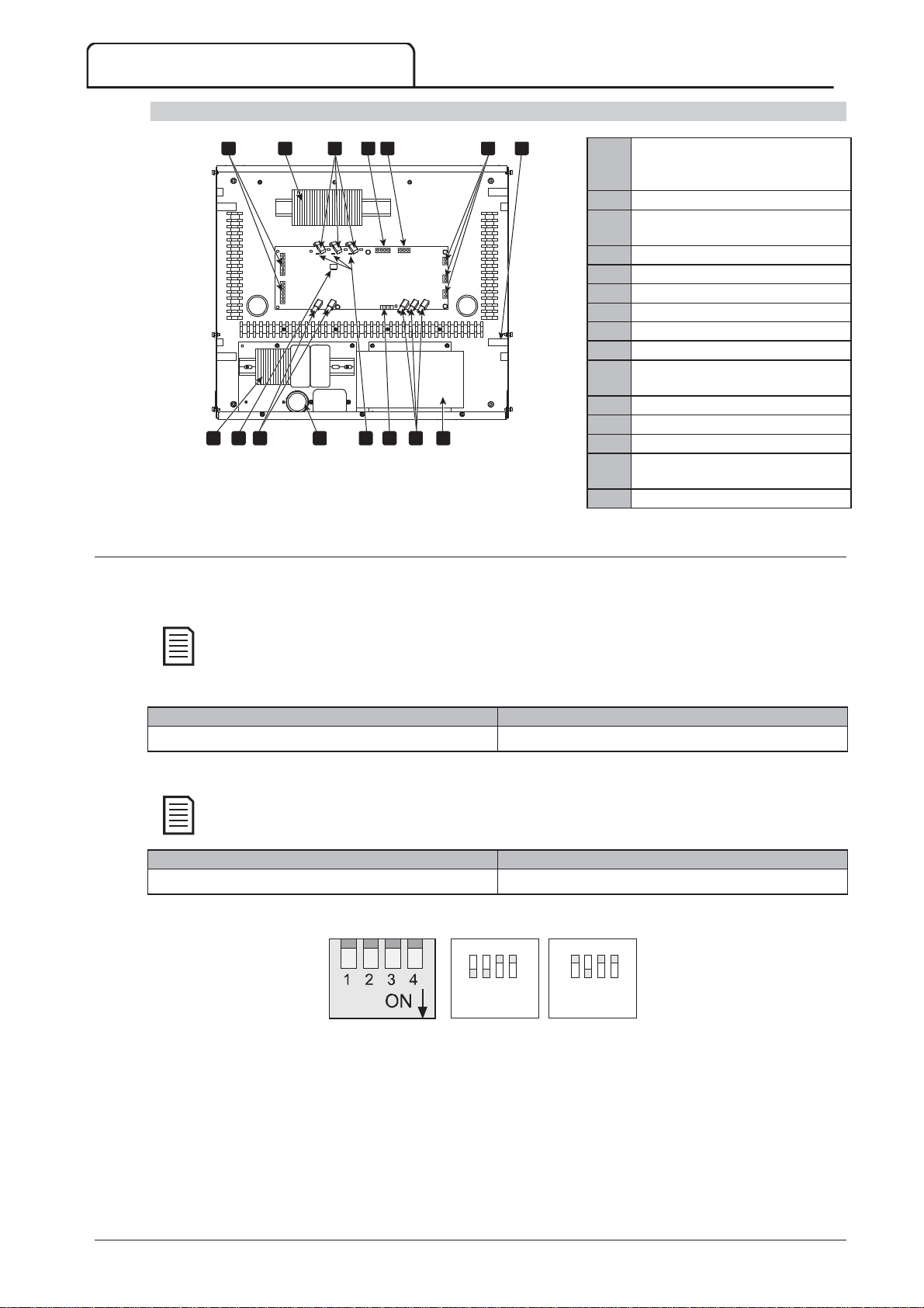
Model V13
1 4
9 1412 15
8
6.13 Ground Current
The ground current selector switches on the power interface board must be set to match the method for
calculating ground current and the ratio of the line current CTs.
2
3
5
6
7
11Control terminals (refer to
Power
Circuit Configuration (model V13)
on page 33 for details)
22LV terminal block X1 and X10
33Gate firing fibre optic connectors
and firing LEDs (red)
C73
1 2 3
C74
13
14
23
24
33
34
43
44
TX RX
V IN
V0 V1 V2 V3
C1 C2 C3 C4 C5 C6
1 2 3
CT3
CT2
CT1
44Voltage sensing input connector
55Ground fault CT connector
66Line CT connectors
77Access hole for CT wiring
88Control voltage terminal block
99CT ratio selector DIP switch S1
110Fibre optic connections to
controller, and LEDs
07234.E
1310 11
111Access for LV wiring
112Non-conduction LEDs (green)
113Alarm inputs
114Non-conduction readback fibre
optic connectors
115Switch mode power supply SMPS1
The soft starter will check the ground fault settings when control power is applied. If the switch settings
are changed, control power must be cycled for the new setting to take effect.
Switch settings for ground current summation method
1000:1 1100
Switch settings for ground current zero sequence method
Zero sequence ground fault measurement requires a customer-supplied ground fault CT. The CT must
be 1000:1, 1 VA, minimum protection class rating 5P10.
1000:1 1100
Example settings for S1
00
11
= 1100 = 0100
0100
16533.A
30 MVS Panel User Manual 710-13937-00C
Page 32
6.14 Power Circuits
Overview
MVS soft starters are designed to operate as part of a system including other components. A main contactor and
bypass contactor are required in all installations. MVS models V02 ~ V07 must be installed with fuses. MVS model
V13 must be installed with either contactor and fuses or a circuit breaker.
The following additional components may also be required:
main isolator/ earth switch
power factor correction
line inductors
transient/ overvoltage protection
MV/LV control supply transformer
Main Contactor
The MVS must always be installed with a main contactor. Select a contactor with an AC3 rating greater than or
equal to the full load current rating of the connected motor or there is an option for a circuit breaker above 7.2 kV.
The main contactor is associated with terminals L1, L2, L3 on the supply side of the soft starter. The coil is
associated with output terminals 13, 14 of the MVS (refer to
page 32).
To ensure that the potentially dangerous medium voltage area is isolated from the low voltage control area, power
is supplied to the main contactor coil from the control voltage terminal block (refer to
page 36).
INSTALLATION
Power Circuit Configuration (models V02 ~ V07)
Internal Wiring –X10
on
on
Bypass Contactor
The MVS must always be installed with a bypass contactor. Select a contactor with an AC1 rating greater than or
equal to the full load current rating of the connected motor or there is an option for a circuit breaker above 7.2 kV.
The bypass contactor is associated with terminals L1, L2, L3 on the supply side of the soft starter, and bypass
terminals T1B, T2B, T3B on the motor side. The coil is associated with output terminals 23, 24, and the auxiliary
Normally Open contact is associated with input terminals C73, C74 of the soft starter (refer to
Configuration (models V02 ~ V07)
To ensure that the potentially dangerous medium voltage area is isolated from the low voltage control area, power
is supplied to the bypass relay coil from the control voltage terminal block (refer to
36).
on page 32).
Internal Wiring –X10
Power Circuit
on page
710-13937-00C MVS Panel User Manual 31
Page 33
INSTALLATION
A1
A4
1
5
2
A2
6
3
A3
4
7
8
A5
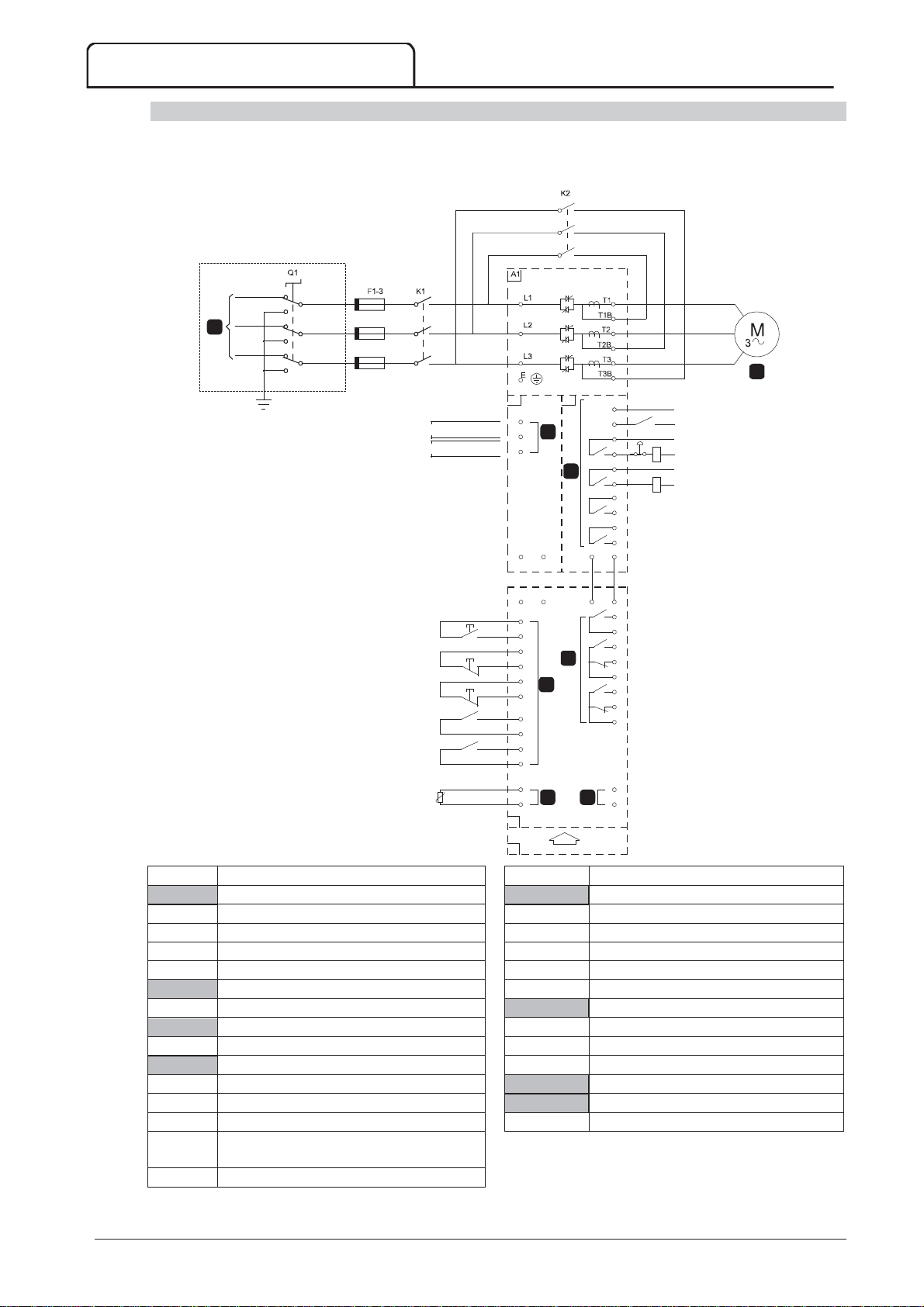
Power Circuit Configuration (models V02 ~ V07)
MVS power circuit with main contactor, bypass contactor, main isolator/ earth switch, R Rated fuses and control
supply. Configured for four-wire start/ stop control. Models V02 to V07 must be installed with backup/R-rated
fuses (refer to R-Rated Protection Fuses)
1
110-130V AC
220-240VAC
2
A1
A2
3
A3
A11 A12
A11
C23
C24
C31
C32
C41
5
C42
C53
C54
C63
C64
B4
7 8
B5
A12
A3
4
6
TX RX
(Bk)(Wh)
(Wh)(Bk)
RX TX
C73
C74
B10
B11
13
14
23
24
33
34
43
44
43
44
54
52
51
64
62
61
+
-
K2
K1
K2
A2
+10
-15
+10
-15
A4
A5
Power assembly A
3 Phase 50/60 Hz Supply
03223.H
Controller
Remote control inputs
Q1 Main isolator/Earth switch C23~C24 Start
F1-3 R-Rated protection fuses C31~C32 Stop
K1 Main contactor C41~C42 Reset
K2 Bypass contactor C53~C54 Programmable input A
To motor C63~C64 Programmable input B
Control voltage terminals
Programmable outputs
Control supply 43, 44 Programmable Relay output A
Power interface board 51, 52, 54 Programmable Relay output B
Relay outputs 61, 62, 64 Programmable Relay output C
C73~C74 Bypass readback signal
13~14 Main contactor (K1)
23~24 Bypass contactor (K2) A
Motor thermistor input
Analog output
Communications module (optional)
33~34 Run output (PFC)
(refer to
Internal Wiring –X10
on page 36).
43~44 Fan control output
32 MVS Panel User Manual 710-13937-00C
Page 34
INSTALLATION
A1
A4
1
5
2
A2
3
A3
6
4
7
8
A5
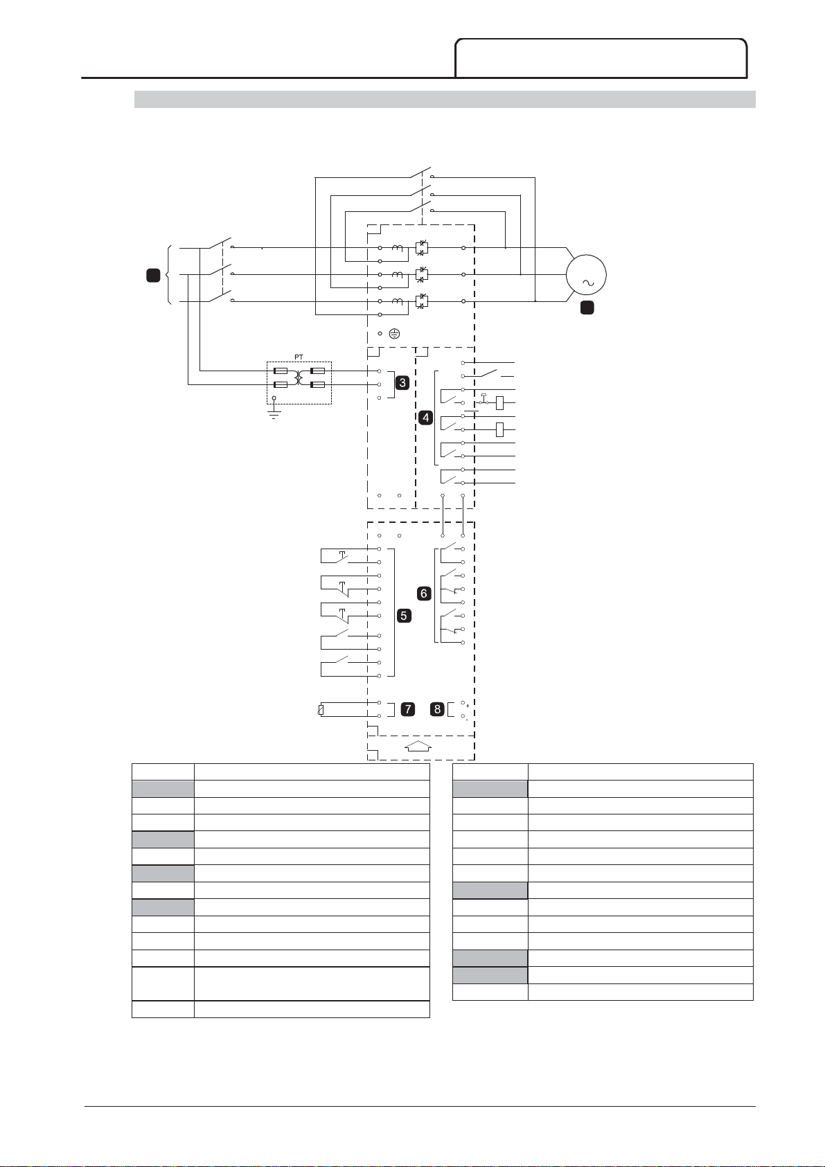
Power Circuit Configuration (model V13)
MVS power circuit with main contactor/circuit breaker and bypass contactor/circuit breaker. Configured for
four-wire start/ stop control with optional MV/LV potential transformer.
K2/Q2
130VAC
A1
A2
L1
L1B
L2
L2B
L3
L3B
E
+10
-15
A1
A2
A3
A11 A12
A11 A12
C23
C24
C31
C32
C41
C42
C53
C54
C63
C64
A3
TX
(Wh)RX(Bk)
(Bk)RX(Wh)
TX
C73
C74
T1
T2
T3
M
3
2
K2/Q2
13
14
23
24
33
34
43
44
43
44
54
52
51
64
62
61
K1/Q1
K2/Q2
K1/Q1
1
B4
B5
A4
A5
Power assembly A
3 Phase 50/60 Hz Supply
B10
B11
07458.D
Controller
Remote control inputs
K1/Q1 Main contactor or circuit breaker C23-24 Start
K2/Q2 Bypass contactor or circuit breaker C31-32 Stop
To motor C41-42 Reset
Control voltage terminals C53-54 Programmable input A
Control supply C63-64 Programmable input B
Power interface board
Programmable outputs
Relay outputs 43-44 Programmable Relay output A
C73-C74 Bypass readback signal 51, 52, 54 Programmable Relay output B
13-14 Main contactor K1 or circuit breaker Q1 61, 62, 64 Programmable Relay output C
23-24 Bypass contactor K2 or circuit breaker Q2
33-34 Run output (PFC)
(refer to
Internal Wiring (model V13)
). A
Motor thermistor input
Analog output
Communications module (optional)
43-44 Fan control output
710-13937-00C MVS Panel User Manual 33
Page 35
INSTALLATION
CAUTION
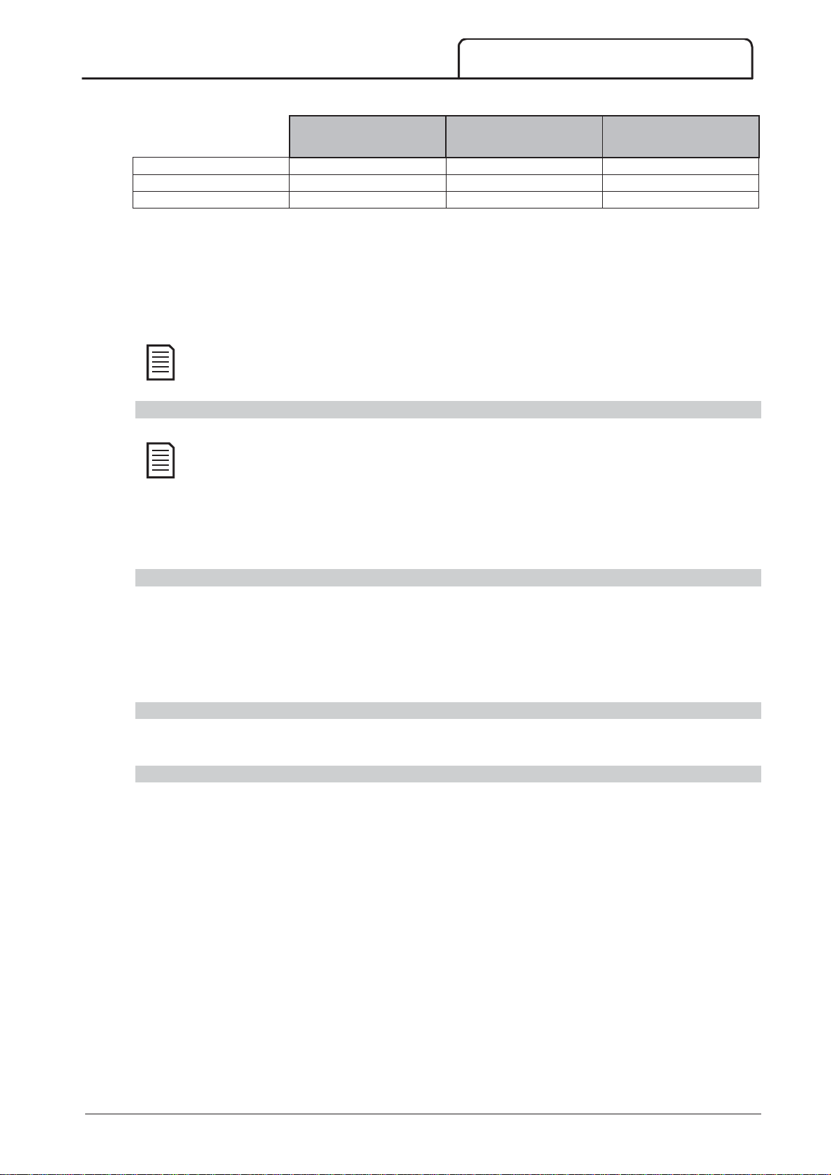
Fuse ratings:
Starter Rated FLC
Fuse
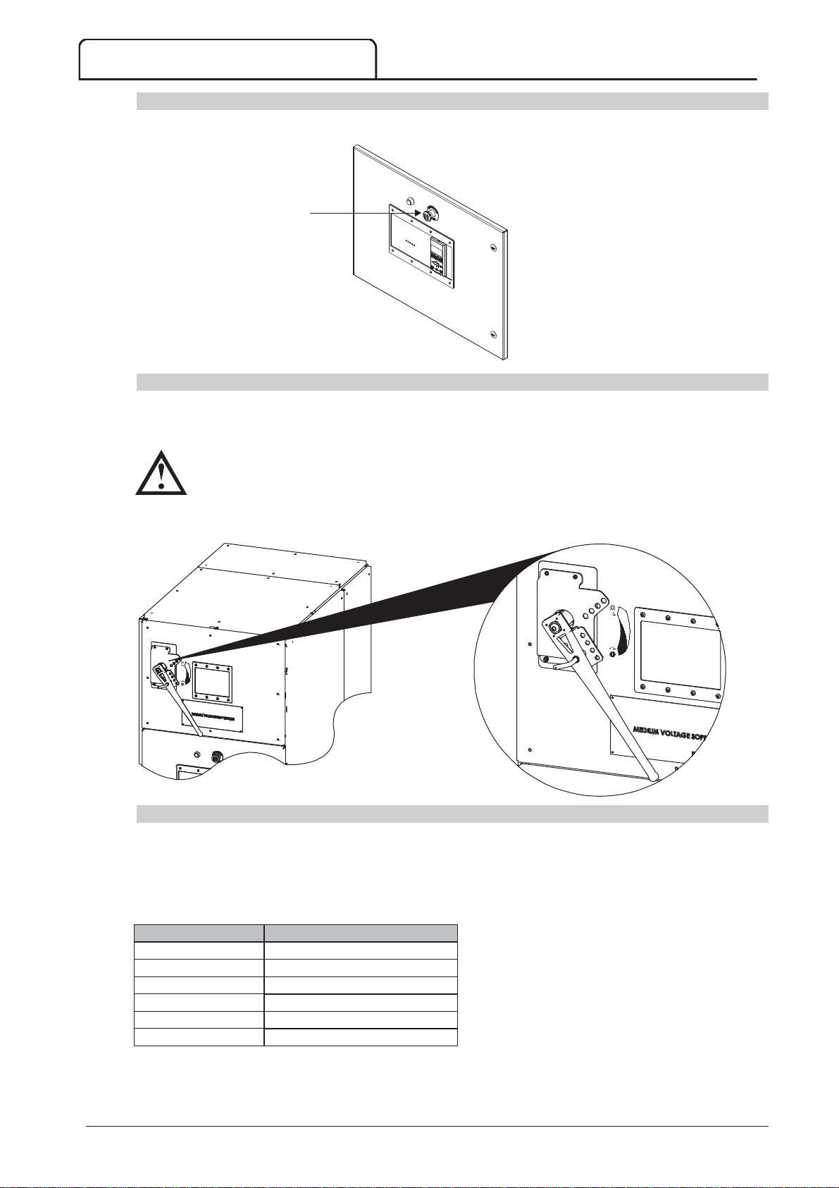
Emergency Stop Button
In the event of an emergency, press the emergency stop button located on the front of the panel.
Main Isolator/ Earth Switch (models V02 ~ V07)
Emergency stop
pushbutton
07620.C
A main isolator/ earth switch can be connected on the supply side of the main contactor (refer to
Configuration (models V02 ~ V07)
on page 32)
Power Circuit
The main isolator/ earth switch must only be operated when the motor is not running and the incoming
mains supply has been disconnected.
To open the isolator, pull out the pin and switch off. If the starter is operating, removing the pin will open the main
contactor.
R Rated Protection Fuses
07619.B
If specified, R Rated protection fuses can be installed on the supply side of the soft starter to provide Type 2
coordination and short circuit protection for the motor branch circuit. The appropriate fuse should be selected
from the table below, based on the motor's rated full load current. MVS models V02 ~ V07 must be installed with
fuses.
80 A 12R
159 A 12R
200 A 12R
230 A 24R
321 A 24R
500 A Selection based on motor current
34 MVS Panel User Manual 710-13937-00C
Page 36
F
Fuse type code formats:
System Voltage
2.3 kV
System Voltage
3.3 ~ 4.2 kV
System Voltage
6 ~ 7.2 kV
Examples:
NOTE
NOTE
INSTALLATION
Ferraz A240Rrr A480Rrr-1 A072xxDxRO-rr
Bussmann JCK-x-rr JCL-x-rr JCR-x-rr
Siba – 400RC315* 400RC315*
* two fuses in parallel
rr = R rating of the fuse
x = physical format of the fuse (select according to installation requirements)
12R fuse for 3.3 kV: A480R12R-1 or JCL-B-12R
24R fuse for 6.6 kV: A072B1DARO-24R or JCR-B-24R
Protection fuses are only required when the switching device used is a contactor.
Power Factor Correction
Do not connect power factor correction capacitors to the output of MVS soft starters. If static power
factor correction is employed, it must be connected to the supply side of the soft starter.
Power factor correction capacitors should be selected based on the motor data and the required final power factor.
If power factor correction capacitors are being used, select a contactor according to the required kVAr. The
contactor must be connected on the supply side of the soft starter. The power factor correction capacitor
contactor coil is associated with output terminals 33, 34 of the soft starter's Interface PCB.
Line Inductors
Output line inductors may be required if the cable run between the soft starter and the motor is greater than 200
metres. Line inductors are typically installed in a shielded caged enclosure at the soft starter end of the motor cable.
Factors which determine the requirement of line inductors are; the soft starter model, system operating voltage,
output cable length and cable type.
Contact your local supplier for advice when using motor output cables exceeding 200 metres. Cable data will be
required, including the capacitance per km of the cable to be used.
Transient/ Overvoltage Protection
Overvoltage protection should be installed if there is a risk of high voltage transients at the installation. Contact your
local supplier for details.
Control Supply Transformer (PT/VT)
The MVS requires a low voltage control supply. If low voltage is not available, a transformer is required. Use a
transformer with primary voltage matching the MV mains voltage, and secondary voltage to suit the MVS starter.
Use a single phase 550 VA transformer with protection fuses on both the primary and secondary sides.
710-13937-00C MVS Panel User Manual 35
Page 37
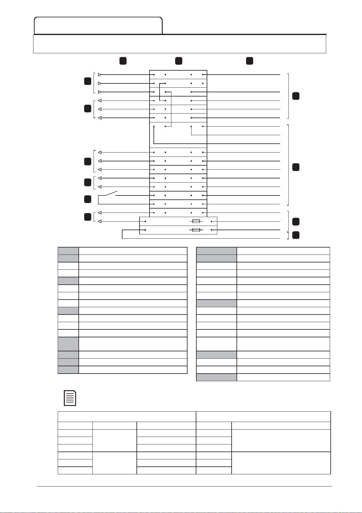
INTERNAL WIRING –X10
A
C
1
7
2
8
3
4
5
9
6
B
10
NOTE
7 Internal Wiring –X10
A
(110-130VAC)
1
(110-240VAC)
(220-240 VAC)
2
3
4
K2
5
(24 VAC)
6
(0 VAC)
16539.A
(1) (2) (3) (4)
A1
A2
A3
A2-1
A2-2
A2-3
13
14
24
34
43
44
C73
C74
A12
A11
A21
A2-1
A2-2
A2-3
C73
C74
A12
A10
A20
A21
A1
A3
CB
PT1-Bk
PT1-Bn
PT1-W1
PT1-W2
PT1-W3
13
23
33
14
24
34
43
44
A3-13
A3-23
A3-33
A3-14
A3-24
A3-34
A3-43
A3-44
A3-C73
A3-C74
PT1-Or5/2
PT1-Or5/1
PT1-Or4/1
A3-A1
7
8
9
10
External wiring
Control supply
Internal wiring
Power transformer (PT1)
A1, A2 110-130 VAC A1 110 V
A2, A3 220-240 VAC A3 220 V
0 VAC for contactor coils A2-1 0 V
A2-1 110/220 VAC coils A2-2 -10 V
A2-2 120/230 VAC coils A2-3 -20 V
A2-3 130/240 VAC coils
Power interface board (A3)
Phase supply for contactor coils A3-13, A3-14 Main contactor output
14 Main contactor coil (K1) A3-23, A3-24 Bypass contactor output
24 Bypass contactor coil (K2) A3-33, A3-34 Run relay output / PFC
34 PFC contactor coil (K3) A3-43, A3-44 Fan control output
Fan control output A3-C73,
Bypass readback signal
A3-C74
Bypass readback signal
24 VAC supply for Controller
24 VAC supply for Controller A10 24 VAC
Power assembly terminal rail (X10) A12 0 VAC
24 VAC supply for interface PCB
The control voltage terminal section (A2) has links fitted for 110 VAC external control and contactor coil
voltages. For other voltages, remove these links and refit as indicated.
External control supply Contactor coil supply (K1 - K3)
Voltage Connect into Link from Voltage Link from
110 VAC A2(2) to A2-1(2) 110 VAC
120 VAC A1, A2 A2(2) to A2-2(2) 120 VAC A1(2) to 13(2)
130 VAC A2(2) to A2-3(2) 130 VAC
220 VAC A2(2) to A2-1(2) 220 VAC
230 VAC A3, A2 A2(2) to A2-2(2) 230 VAC A3(2) to 13(2)
240 VAC A2(2) to A2-3(2) 240 VAC
36 MVS Panel User Manual 710-13937-00C
Page 38
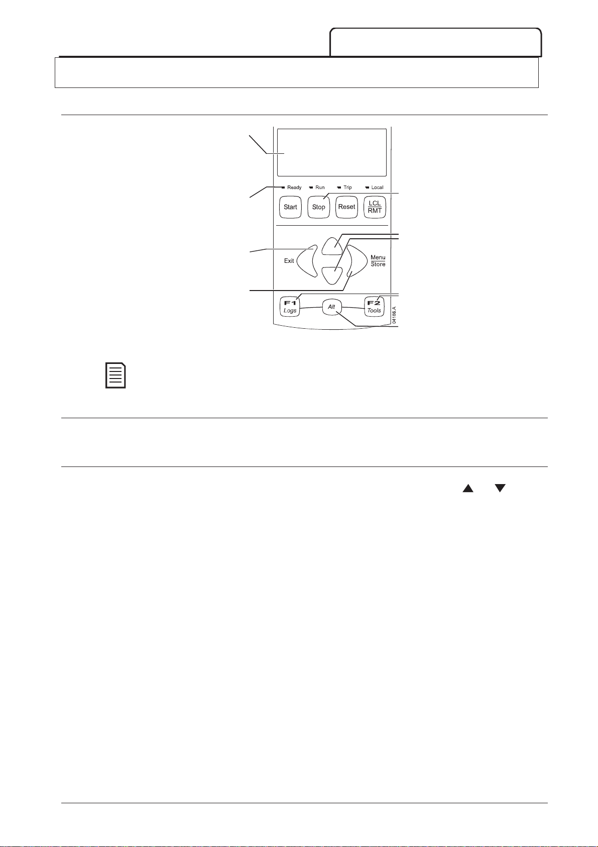
NOTE
8 Keypad and Feedback
8.1 The Controller
KEYPAD AND FEEDBACK
Four-line display for status and programming
Menu navigation buttons:
Exit the menu or parameter, or cancel a
Enter a menu or parameter, or save a
When the Controller is powered up, the Ready LED flashes for 5 seconds as part of the initialisation
routine.
8.2 Menu Shortcuts
details.
Status LEDs
parameter change.
parameter change.
Soft starter local control buttons
Menu navigation buttons:
Scroll to the next or previous menu or
parameter, or change the setting of the
current parameter.
Shortcut buttons for quick access to
common tasks.
Alt button. Use with F1 or F2 to open
performance logs or commissioning
tools.
The F1 and F2 buttons offer keyboard shortcuts to the Auto-Stop menu. Use parameters 8B and 8C (
and F2 Button Action
8.3 Displays
The controller displays a wide range of performance information about the soft starter. The top half of the screen
shows real-time information on current or motor power (as selected in parameter 8D). Use the
buttons to select the information shown on the bottom half of the screen.
Starter status
User programmable screen
Motor temperature
Current
Motor power
Voltage
Last start information
Date and time
Performance graphs
SCR conduction
Refer to
Operating Feedback
8B, 8C – F1
on page 52) to select the shortcut target.
and
on page 70, for further details.
710-13937-00C MVS Panel User Manual 37
Page 39
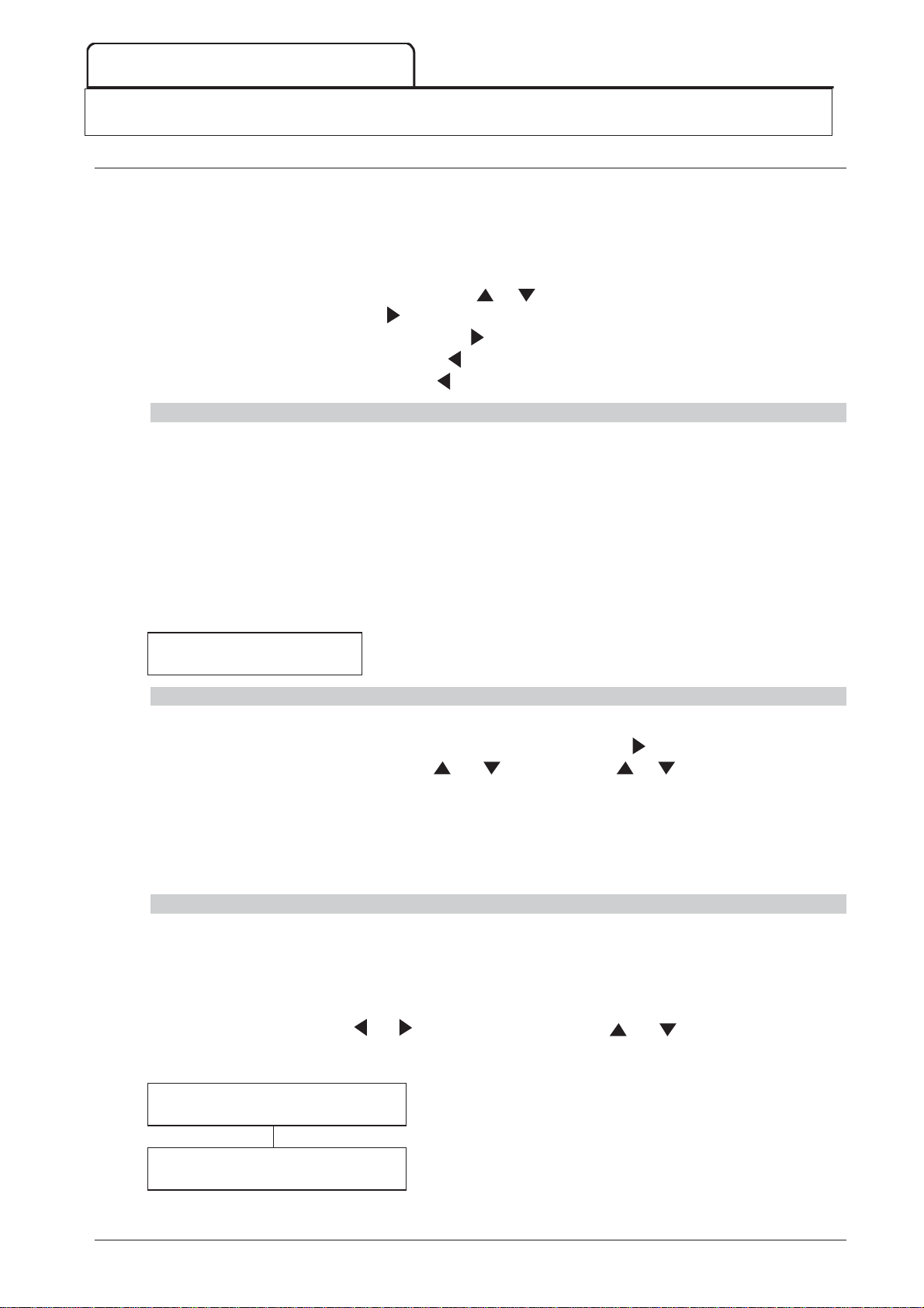
CONFIGURATION
MENU
STORE
EXIT
STORE
STORE
9 Configuration
9.1 Programming Menu
The Programming Menu lets you view and change programmable parameters that control how the MVS operates.
You can access the Programming Menu at any time, including while the soft starter is running. Any changes to the
start profile take effect immediately.
To open the Programming Menu, press the M
To navigate through the Programming Menu:
to scroll through parameter groups, press the
to open a submenu, press the
to view the parameters in a group, press the
to return to the previous level, press the
to close the Programming Menu, press
Adjustment Lock
You can lock the Programming Menu to prevent users from altering parameter settings. The adjustment lock can
be turned on and off using parameter 15B.
To lock the programming menu:
1. Open the Programming Menu.
2. Open the Extended Menu.
3. Select 'Advanced'.
4. Enter the Access Code.
5. Select parameter 15B
6. Select and store 'Read Only'.
If a user attempts to change a parameter value when the adjustment lock is active, an error message is displayed:
Adjustment Lock
button.
button while viewing the monitoring screens.
or button.
button.
button.
repeatedly.
Access Denied
Adj Lock is On
Altering Parameter Values
To change a parameter value:
scroll to the appropriate parameter in the Programming Menu and press
to alter the parameter setting, use the
decrease the value by one unit. If the button is held for longer than five seconds, the value will increase
or decrease at a faster rate.
to save changes, press S
return to the parameter list.
to cancel changes, press E
without saving changes.
. The setting shown on the display will be saved and the controller will
. The controller will ask for confirmation, then return to the parameter list
and buttons. Pressing or once will increase or
Access Code
Critical parameters (parameter group 15 and higher) are protected by a four-digit security access code, preventing
unauthorised users from viewing or modifying parameter settings.
When a user attempts to enter a restricted parameter group, the controller prompts for an access code. The
access code is requested once for the programming session, and authorisation continues until the user closes the
menu.
To enter the access code, use the
value. When all four digits match your access code, press
message before continuing.
and buttons to select a digit, and the and buttons to change the
. The controller will display an acknowledgement
to enter edit mode.
Enter Access Code
0###
Access Allowed
SUPERVISOR
To change the access code, use parameter 15A.
38 MVS Panel User Manual 710-13937-00C
Page 40
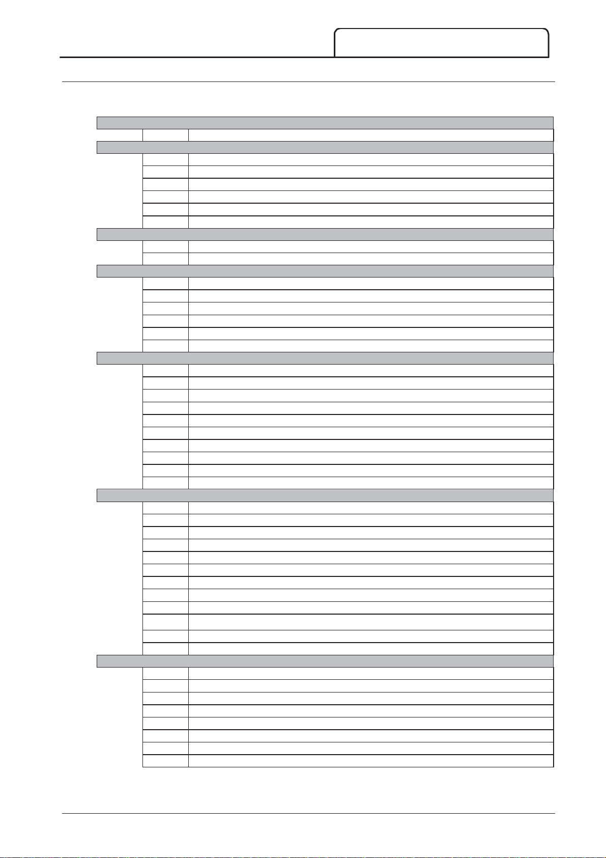
9.2 Standard Menu
1MMotor Data--11
2SStart/Stop Modes--11
3AAuto--SStart/Stop
4PProtection
6IInputs
7OOutputs
8DDisplay
The standard menu provides access to commonly used parameters, allowing the user to configure the MVS as
required for the application. For details of individual parameters, refer to
1
1A
2
2A
2B
2C
2D
2H
2I
3
3C
3D
4
4A
4C
4D
4E
4F
4G
6
6A
6B
6C
6D
6E
6F
6G
6H
6I
6J
7
7A
7B
7C
7D
7E
7F
7G
7H
7I
7M
7N
7O
8
8A
8B
8C
8D
8E
8F
8G
8H
Motor Full Load Current
Start Mode
Start Ramp Time
Initial Current
Current Limit
Stop Mode
Stop Time
Auto-Stop Type
Auto-Stop Time
Excess Start Time
Undercurrent
Undercurrent Delay
Instantaneous Overcurrent
Instantaneous Overcurrent Delay
Phase Sequence
Input A Function
Input A Name
Input A Trip
Input A Trip Delay
Input A Initial Delay
Input B Function
Input B Name
Input B Trip
Input B Trip Delay
Input B Initial Delay
Relay A Function
Relay A On Delay
Relay A Off Delay
Relay B Function
Relay B On Delay
Relay B Off Delay
Relay C Function
Relay C On Delay
Relay C Off Delay
Low Current Flag
High Current Flag
Motor Temperature Flag
Language
F1 Button Action
F2 Button Action
Display A or kW
User Screen - Top Left
User Screen - Top Right
User Screen - Bottom Left
User Screen - Bottom Right
CONFIGURATION
Parameter Descriptions
on page 43.
710-13937-00C MVS Panel User Manual 39
Page 41
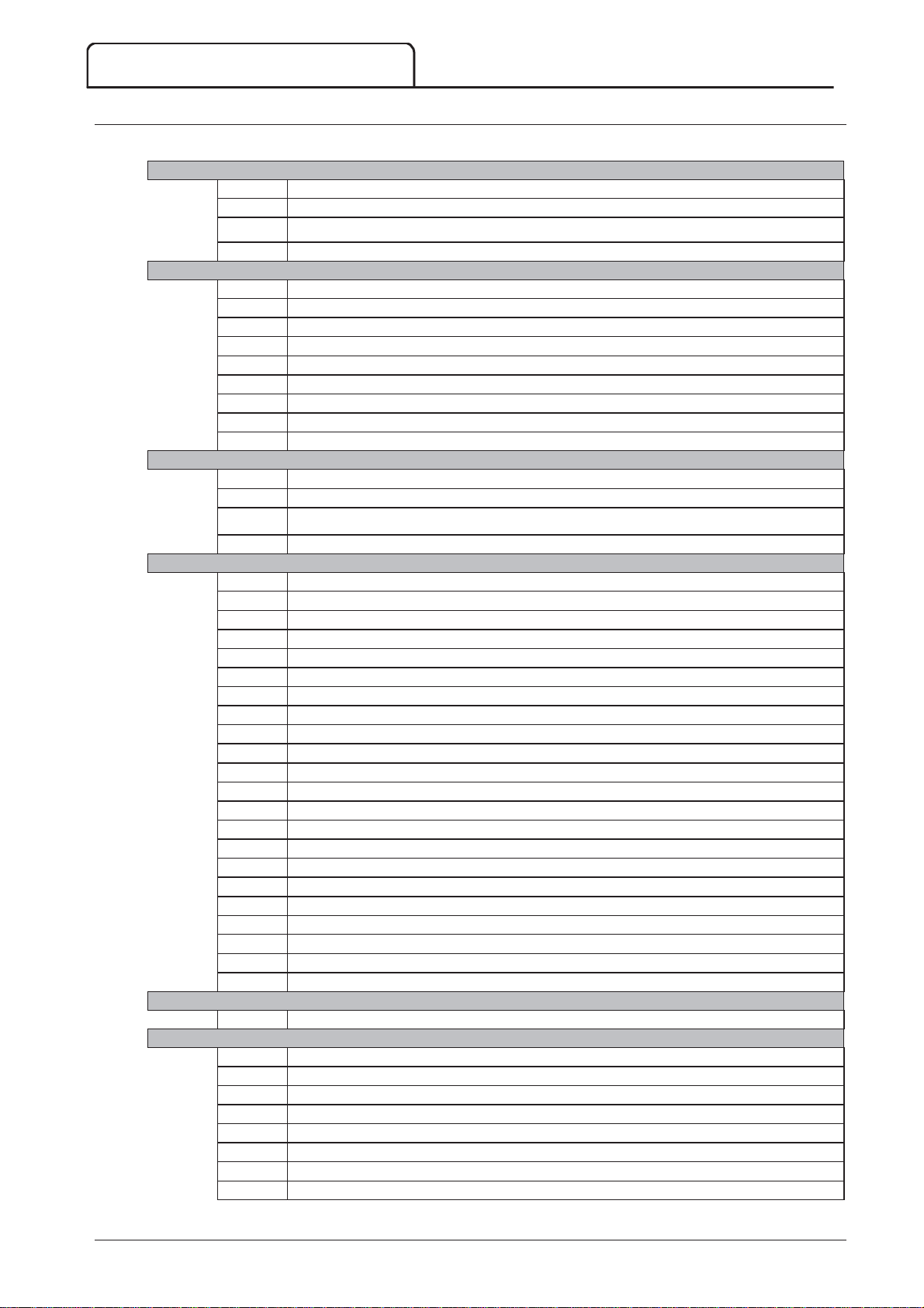
CONFIGURATION
1MMotor Data--11
2SStart/Stop Modes--11
3AAuto--SStart/Stop
4PProtection
5AAuto--RReset Trips (
Reserved
)
6IInputs
9.3 Extended Menu
The extended menu gives access to all of the MVS's programmable parameters.
1
1A
1B
1C
1D
2
2A
2B
2C
2D
2E
2F
2G
2H
2I
3
3A
3B
3C
Motor Full Load Current
Locked Rotor Time
Locked Rotor Current
Motor Service Factor
Start Mode
Start Ramp Time
Initial Current
Current Limit
Reserved
Kickstart Time
Kickstart Level
Stop Mode
Stop Time
Reserved
Reserved
Auto-Stop Type
3D
4
4A
4B
4C
4D
4E
4F
4G
4H
4I
4J
4K
4L
4M
4N
4O
4P
4Q
4R
4S
4T
4U
4V
5
5A
6
6A
6B
6C
6D
6E
6F
6G
6H
Auto-Stop Time
Excess Start Time
Excess Start Time-2
Undercurrent
Undercurrent Delay
Instantaneous Overcurrent
Instantaneous Overcurrent Delay
Phase Sequence
Current Imbalance
Current Imbalance Delay
Frequency Check
Frequency Variation
Frequency Delay
Restart Delay
Motor Temperature Check
Ground Fault Level
Ground Fault Delay
Undervoltage
Undervoltage Delay
Overvoltage
Overvoltage Delay
Instantaneous Overcurrent S2
Instantaneous Overcurrent Delay S2
R
)
Reserved
Input A Function
Input A Name
Input A Trip
Input A Trip Delay
Input A Initial Delay
Input B Function
Input B Name
Input B Trip
40 MVS Panel User Manual 710-13937-00C
Page 42
CONFIGURATION
7OOutputs
8DDisplay
9MMotor Data--22
10SStart/Stop Modes--22
6I
6J
6K
6L
6M
6N
6O
6P
6Q
6R
7
7A
7B
7C
7D
7E
7F
7G
7H
7I
7J
7K
7L
7M
7N
7O
7P
7Q
7R
7S
7T
7U
7V
7W
8
8A
8B
8C
8D
8E
8F
8G
8H
8I
8J
8K
8L
8M
9
9A
9B
9C
9D
9E
1
10A
10B
10C
Input B Trip Delay
Input B Initial Delay
Reserved
Reserved
Remote Reset Logic
Reserved
Reserved
Reserved
Local/Remote
Comms in Remote
Relay A Function
Relay A On Delay
Relay A Off Delay
Relay B Function
Relay B On Delay
Relay B Off Delay
Relay C Function
Relay C On Delay
Relay C Off Delay
Reserved
Reserved
Reserved
Low Current Flag
High Current Flag
Motor Temperature Flag
Analog Output A
Analog A Scale
Analog A Maximum Adjustment
Analog A Minimum Adjustment
Reserved
Reserved
Reserved
Reserved
Language
F1 Button Action
F2 Button Action
Display A or kW
User Screen - Top Left
User Screen - Top Right
User Screen - Bottom Left
User Screen - Bottom Right
Graph Data
Graph Timebase
Graph Maximum Adjustment
Graph Minimum Adjustment
Mains Reference Voltage
Reserved
Motor FLC-2
Reserved
Reserved
Reserved
Start Mode-2
Start Ramp-2
Initial Current-2
710-13937-00C MVS Panel User Manual 41
Page 43
CONFIGURATION
11RRTD/PT100 (
Reserved
)
12SSlip--RRing Motors
15AAdvanced
16PProtection Action
10D
10E
10F
10G
10H
10I
1
11A
1
12A
12B
12C
12D
1
15A
15B
15C
1
16A
16B
16C
16D
16E
16F
16G
16H
16I
16J
16K
16L
16M
16N
16O
16P
16Q
16R
16S
16T
16U
16V
16W
Current Limit-2
Reserved
Kickstart Time-2
Kickstart Level-2
Stop Mode-2
Stop Time-2
R
)
Reserved
Motor Data-1 Ramp
Motor Data-2 Ramp
Changeover Time
Slip Ring Retard
Access Code
Adjustment Lock
Emergency Run
Motor Overload
Excess Start Time
Undercurrent
Instantaneous Overcurrent
Current Imbalance
Frequency
Input A Trip
Input B Trip
Motor Thermistor
Starter Communication
Network Communication
Reserved
Battery/Clock
Ground Fault
Reserved
Reserved
Reserved
Reserved
Reserved
Reserved
Reserved
Undervoltage
Overvoltage
42 MVS Panel User Manual 710-13937-00C
Page 44
9.4 Load/Save Settings
STORE
1A – Motor FLC
Range:
Default:
Description:
1B – Locked Rotor Time
Range:
Default:
Description:
1C – Locked Rotor Current
Range:
Default:
Description:
1D – Motor Service Factor
Range:
Default:
Description:
2A – Start Mode
Options:
Description:
2B – Start Ramp Time
Range:
Default:
Description:
The Load/Save Settings menu requires an access code and allows users to:
Load the MVS's parameters with default values
Reload previously saved parameter settings from an internal file
Save the current parameter settings to an internal file
In addition to the factory default values file, the MVS can store two user-defined parameter files. These files contain
default values until a user file is saved.
To load or save settings:
CONFIGURATION
2. Open the Programming Menu
3. Scroll to Load/Save Settings and press the
4. Scroll to the required function and press the
access code when prompted.
5. At the confirmation prompt, select YES to confirm or NO to cancel
and then S
When the action has been completed, the screen will briefly display a
confirmation message, then return to the Load/Save Settings screen
to load/save the selection.
9.5 Parameter Descriptions
1 Motor Data-1
The parameters in Motor Data-1 configure the soft starter to match the connected motor. These parameters
describe the motor's operating characteristics and allow the soft starter to model the motor's temperature.
5 - 1200 A D
Matches the starter to the connected motor's full load current. Set to the full load
current (FLC) rating shown on the motor nameplate.
0:01 - 2:00 (minutes:seconds) D
Sets the maximum length of time the motor can sustain locked rotor current from cold
before reaching its maximum temperature. Set according to the motor datasheet.
button.
button. Enter the
Load Defaults
Load Backup
Load User Set 1
Load Defaults
No
Yes
100 A
10 seconds
400% - 1200% FLC D
Sets the locked rotor current of the connected motor, as a percentage of full load
current. Set according to the motor datasheet.
100% - 130% D
Sets the motor service factor used by the thermal model. If the motor runs at full load
current, it will reach 100%. Set according to the motor datasheet.
600%
105%
2 Start/Stop Modes-1
710-13937-00C MVS Panel User Manual 43
Constant Current (default)
Selects the soft start mode.
0:01 - 3.00 (minutes:seconds) D
Sets the ramp time for current ramp starting (from the initial current to the current
limit).
1 second
Page 45
CONFIGURATION
2C – Initial Current
Range:
Default:
Description:
2D – Current Limit
Range:
Default:
Description:
2E – Reserved
Description:
2F – Kickstart Time
Range:
Default:
Description:
2G – Kickstart Level
Range:
Default:
Description:
CAUTION
2H – Stop Mode
Options:
Description:
2I – Stop Time
Range:
Default:
Description:
WARNING
3A, 3B – Reserved
Description:
3C – Auto-Stop Type
Options:
Description:
3D – Auto-Stop Time
Range:
Default:
Description:
2
100% - 600% FLC D
Sets the initial start current level for current ramp starting, as a percentage of motor full
load current. Set so that the motor begins to accelerate immediately after a start is
initiated.
If current ramp starting is not required, set the initial current equal to the current limit.
100% - 600% FLC D
Sets the current limit for constant current and current ramp soft starting, as a
percentage of motor full load current.
This parameter is reserved for future use.
0 – 2000 milliseconds D
Sets the kickstart duration. A setting of 0 disables kickstart.
100% - 700% FLC D
Sets the level of the kickstart current.
400%
400%
0000 milliseconds
500%
Kickstart subjects the mechanical equipment to increased torque levels. Ensure the motor, load and
couplings can handle the additional torque before using this feature.
Coast To Stop (default)
TVR Soft Stop
Selects the stop mode.
0:00 - 4:00 (minutes:seconds) D
Sets the time for soft stopping the motor using timed voltage ramp.
If a main contactor is installed, the contactor must remain closed until the end of the
stop time.
0 second
3 Auto-Stop
The MVS can be programmed to stop automatically, after a specified delay or at a specified time of day.
This function should not be used in conjunction with remote two-wire control.
The soft starter will still accept start and stop commands from the remote inputs or serial communication
network. To disable local or remote control, use parameter 6Q.
These parameters are reserved for future use.
Off (default) The soft starter will not auto-stop.
Timer The soft starter will auto-stop after a delay from the next
start, as specified in parameter 3D.
Clock The soft starter will auto-stop at the time programmed in
parameter 3D.
Selects whether the soft starter will auto-stop after a specified delay, or at a time of day.
44 MVS Panel User Manual 710-13937-00C
00:01 - 24:00 (hours:minutes) D
Sets the time for the soft starter to auto-stop, in 24 hour clock format.
1 minute
Page 46
CONFIGURATION
CAUTION
4A – Excess Start Time
Range:
Default:
Description:
4B – Excess Start Time-2
Range:
Default:
Description:
4C – Undercurrent
Range:
Default:
Description:
4D – Undercurrent Delay
Range:
Default:
Description:
4E, 4F – Instantaneous Overcurrent
Range:
Default:
Description:
Range:
Default:
Description:
NOTE
4G – Phase Sequence
Options:
Description:
4 Protection Settings
These parameters determine when the soft starter's protection mechanisms will activate. The activation point for
each protection mechanism can be set to suit the installation.
The soft starter responds to protection events by tripping, warning, or writing the event to the event log. The
response is determined by the Protection Action settings. The default response is a trip.
C
The protection settings are vital for safe operation of the soft starter and motor. Defeating the
protection may compromise the installation and should only be done in the case of emergency.
4
Excess start time is the maximum time the MVS will attempt to start the motor. If the motor does not
transition to Run mode within the programmed limit, the starter will trip. Set for a period slightly longer
than required for a normal healthy start. A setting of 0 disables excess start time protection.
0:00 - 4:00 (minutes:seconds) D
Set as required.
0:00 - 4:00 (minutes:seconds) D
Set as required.
0% - 100% D
Sets the trip point for undercurrent protection, as a percentage of motor full load
current. Set to a level between the motor's normal working range and the motor's
magnetising (no load) current (typically 25% to 35% of full load current). A setting of
0% disables undercurrent protection.
20 seconds
20 seconds
20%
The MVS can be configured to trip if the average current of all three phases exceeds a specified level while
the motor is running. Refer to
information and examples.
Parameter 4E
Parameter 4F
This protection is only active during run and must be coordinated with
Stage 2
(parameters 4U, 4V).
0:00 - 4:00 (minutes:seconds) D
Slows the MVS's response to undercurrent, avoiding trips due to momentary
fluctuations.
Instantaneous Overcurrent
80% - 600% FLC D
Sets the trip point for instantaneous overcurrent protection, as a percentage of motor
full load current.
Instantaneous Overcurrent Delay
0:00 - 1:00 (minutes:seconds) D
Slows the MVS's response to overcurrent, avoiding trips due to momentary overcurrent
events.
Any Sequence
Positive Only (default)
Negative Only
Selects which phase sequences the soft starter will allow at a start. During its pre-start
checks, the starter examines the sequence of the phases at its input terminals and trips if
the actual sequence does not match the selected option.
4U, 4V – Instantaneous Overcurrent Stage 2
Instantaneous Overcurrent
5 seconds
on page 47 for more
400%
0 second
710-13937-00C MVS Panel User Manual 45
Page 47
CONFIGURATION
4H – Current Imbalance
Range:
Default:
Description:
4I – Current Imbalance Delay
Range:
Default:
Description:
NOTE
4J – Frequency Check
Options:
Description:
4K – Frequency Variation
Options:
Description:
4L – Frequency Delay
Range:
Default:
Description:
NOTE
4M – Restart Delay
Range:
Default:
Description:
4N – Motor Temperature Check
Options:
Description:
4O – Ground Fault Level
Range:
Default:
Description:
4P – Ground Fault Delay
Range:
Default:
Description:
NOTE
4
The MVS will display a Current Imbalance trip only when phase loss at the supply terminals occurs during
Run mode. When a phase loss occurs during other modes of operation, the MVS will trip on Motor
Connection.
10% - 50% D
30%
Sets the trip point for current imbalance protection.
0:00 - 4:00 (minutes:seconds) D
5 seconds
Slows the MVS's response to current imbalance, avoiding trips due to momentary
fluctuations.
Do Not Check
Start Only
Start/Run
Run Only (default)
Determines when and if the starter will monitor for a frequency trip.
± 2 Hz
± 5 Hz (default)
± 10 Hz
± 15 Hz
Selects the soft starter's tolerance for frequency variation.
0:01 - 4:00 (minutes:seconds) D
5 seconds
Slows the MVS's response to frequency disturbances, avoiding trips due to momentary
fluctuations.
If the mains frequency drops below 35 Hz or rises above 75 Hz, the starter will trip immediately,
irrespective of the settings for Frequency Trip parameters.
00:01 - 60:00 (minutes:seconds) D
The MVS can be configured to force a delay between the end of a stop and the
beginning of the next start. During the restart delay period, the display shows the time
remaining before another start can be attempted.
Do Not Check (default)
Check
Selects whether the MVS will verify the motor has sufficient thermal capacity for a
successful start. The soft starter compares the motor's calculated temperature with the
temperature rise from the last motor start and only operates if the motor is cool
enough to start successfully.
1A-40 A D
Sets the trip point for ground fault protection. Ground fault is a dynamic trip based on
phase current measurements every half-cycle.
0:01 - 4:00 (minutes:seconds) D
Slows the MVS's response to ground fault variation, avoiding trips due to momentary
fluctuations.
30 minutes
1A
3 seconds
Ground fault accuracy is within ± 1 A of the set value.
46 MVS Panel User Manual 710-13937-00C
Page 48
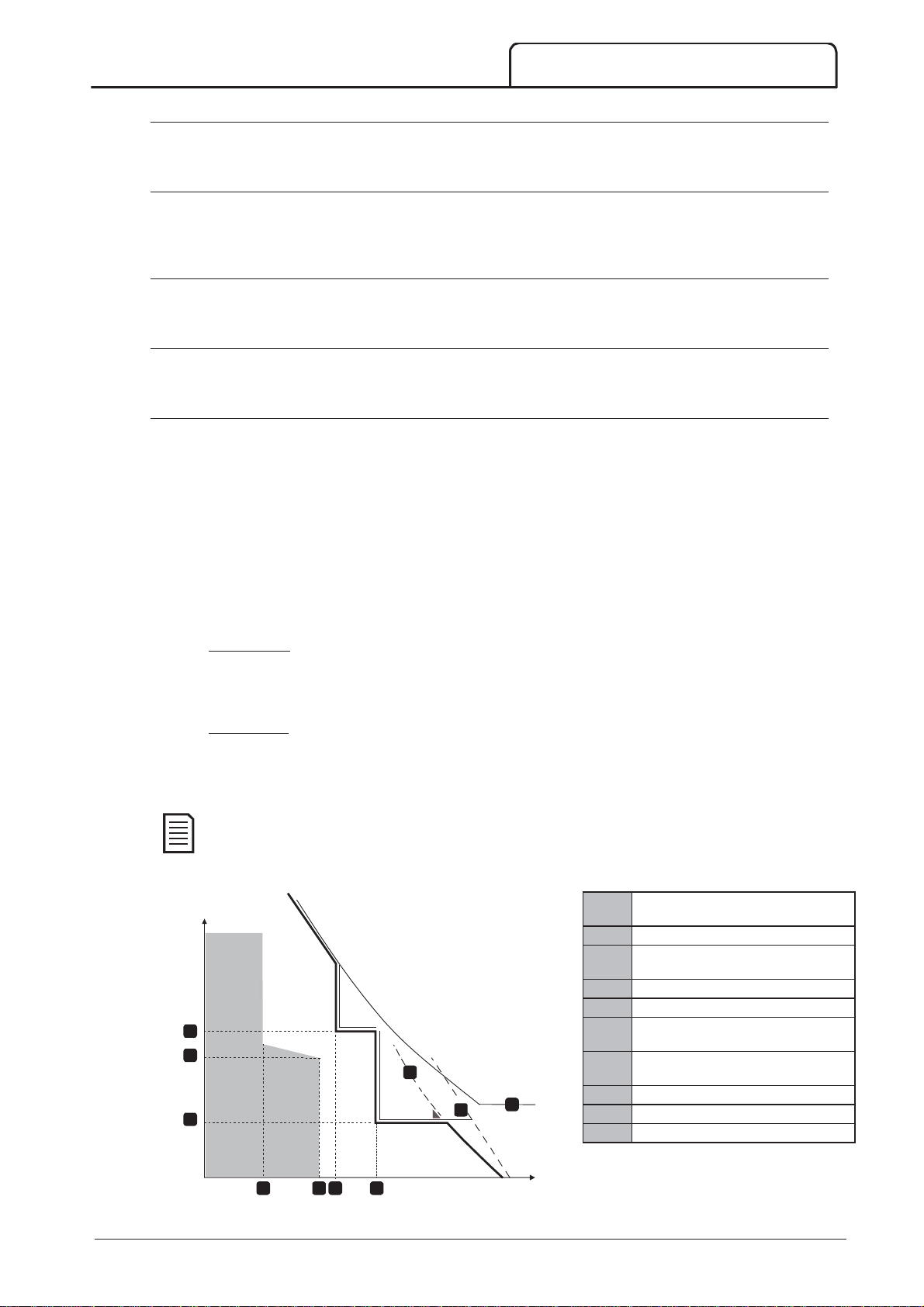
CONFIGURATION
4Q Undervoltage Level
Range:
Default:
Description:
4R Undervoltage Trip Delay
Range:
Default:
Description:
4S Overvoltage Level
Range:
Default:
Description:
4T Overvoltage Trip Delay
Range:
Default:
Description:
4U, 4V – Instantaneous Overcurrent Stage 2
Range:
Default:
Description:
Range:
Default:
Description:
NOTE
1
2
3
4
5
6
7
8
9
10
4
100 – 18000 V D
Sets the trip point for undervoltage protection. Set as required.
100 V
0:00 – 4:00 (minutes:seconds) D
Slows the MVS's response to undervoltage, avoiding trips due to momentary
5 seconds
fluctuations.
100 – 18000 V D
Sets the trip point for overvoltage protection. Set as required.
7200 V
0:00 – 4:00 (minutes:seconds) D
Slows the MVS's response to overvoltage, avoiding trips due to momentary fluctuations.
5 seconds
The MVS has two instantaneous trip functions, stage 1 and 2. These protection functions are configured to be
complementary.
Stage 1 must be configured to protect the motor against a locked rotor (shearpin) situation during run mode.
Stage 1 should trigger at lower current/higher time values than Stage 2.
Stage 2 must be configured to protect the main switching device. When Stage 2 triggers, the starter opens the
main switching device.
If the main switching element is a contactor (protected by a fuse), then this function must be coordinated with the
fuse to ensure that the contactor does NOT open until the fuse ruptures.
If the main switching element is a breaker, then the delay must be minimised to provide the best possible protection
to the SCR.
Parameter 4U
Instantaneous Overcurrent S2
30 A – 4400 A D
4400 A
Sets the trip point for instantaneous overcurrent stage 2 protection in amperes. Set as
required.
Parameter 4V
Instantaneous Overcurrent Delay S2
10 – 1000 ms D
10 milliseconds
Sets the duration required for current to exceed the level set in parameter 4U before a
trip occurs. Set as required.
This protection is active during starting, running and stopping. It must be coordinated with
Overcurrent
(parameters 4E, 4F).
Instantaneous
Example: Contactor and Fuse
Instantaneous Overcurrent Delay Stage 1 (4F)
Motor start time
Instantaneous Overcurrent Delay -
Stage 2 (4V)
FLC
Motor start current
1
2
Time
8
3
4
6 75
9
Current
710-13937-00C MVS Panel User Manual 47
10
07248.E
Shaded area indicates motor operation
Instantaneous Overcurrent- Stage 1
(4E)
Instantaneous Overcurrent - Stage 2
(4U) to trip external upstream breaker
Fuse
SCR
Thermal model curve
Page 49
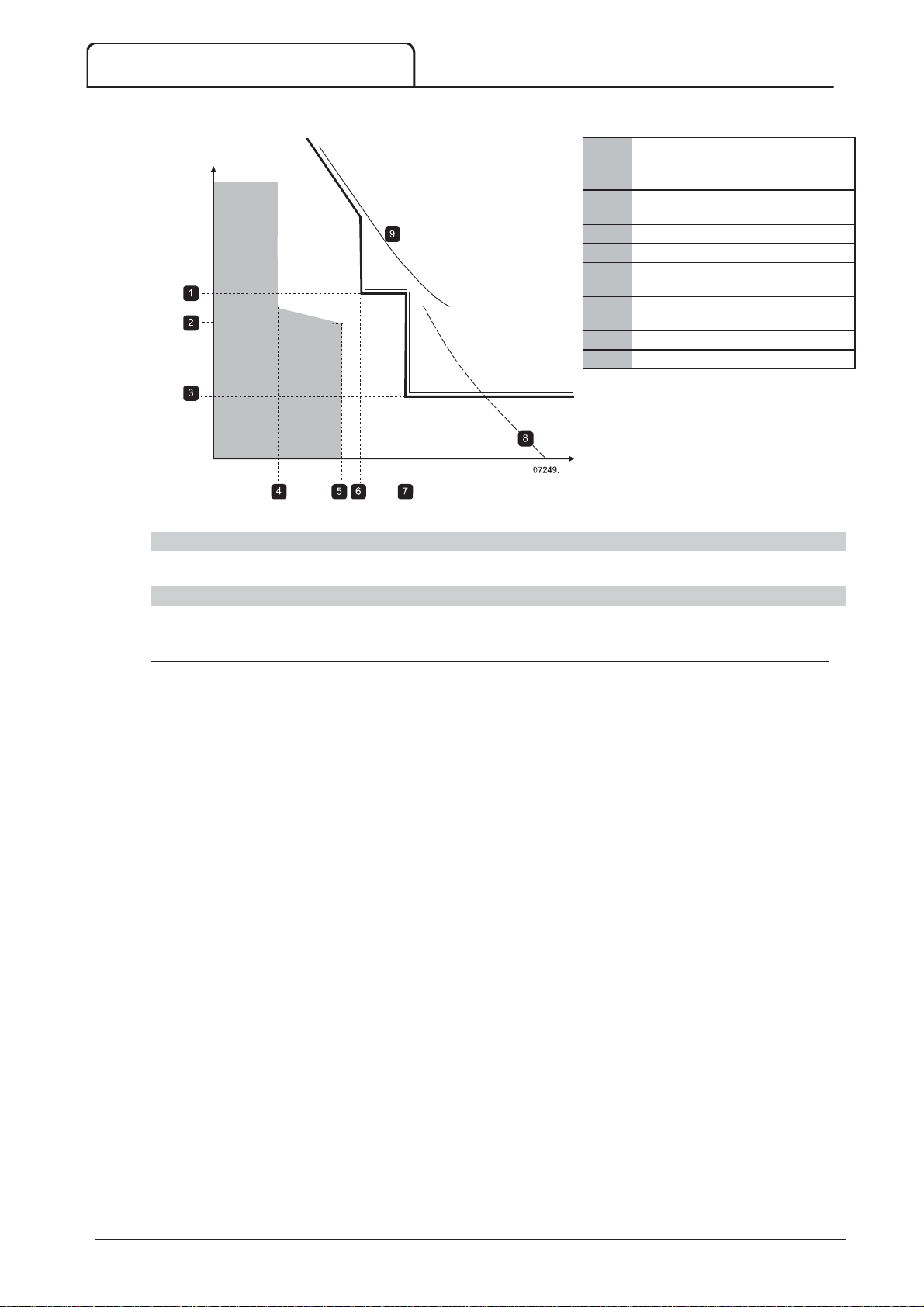
CONFIGURATION
1
2
3
4
5
6
7
8
9
6A – Input A Function
Options:
LCL/RMT
START
LCL/RMT
Example: Circuit Breaker
Time
Instantaneous Overcurrent Delay Stage 1 (4F)
Motor start time
Instantaneous Overcurrent Delay -
Stage 2 (4V)
FLC
Motor start time
Instantaneous Overcurrent -Stage 1
(4E)
Instantaneous Overcurrent -Stage 2
(4U) to trip main breaker
SCR
Thermal model curve
C
Current
Shaded area indicates motor operation
5 Auto-Reset Trips (Reserved)
This parameter group is reserved for future use.
6 Inputs
The MVS has two programmable inputs, which allow remote control of the soft starter.
Motor Set Select The MVS can be configured with two separate sets of
motor data.
To use the secondary motor data, parameter 6A must be
set to 'Motor Set Select' and C53, C54 must be closed
when a start command is given. The MVS checks which
motor data to use at a start, and will use that motor data
for the entire start/stop cycle.
Input Trip (N/O) (default) Input A can be used to trip the soft starter. When
parameter 6A is set to Input Trip (N/O), a closed circuit
across C53, C54 trips the soft starter.
(Refer to parameters 6C, 6D, 6E)
Input Trip (N/C) When parameter 6A is set to Input Trip (N/C), an open
circuit across C53, C54 trips the soft starter.
(Refer to parameters 6C, 6D, 6E)
Local/Remote Select Input A can be used to select between local and remote
control, instead of using the L
controller. When the input is open, the starter is in local
mode and can be controlled via the controller. When the
input is closed, the starter is in remote mode. The
and L
starter will ignore any Local/Remote select command from
the serial communications network.
To use Input A to select between local and remote
control, parameter 6Q must be set to 'LCL/RMT Anytime'
or 'LCL/RMT When Off'.
Emergency Run In emergency run the soft starter continues to run until
stopped, ignoring all trips and warnings (refer to parameter
15C for details).
Closing the circuit across C53, C54 activates emergency
run.
Opening the circuit ends emergency run and the MVS
stops the motor.
buttons are disabled, and the soft
button on the
48 MVS Panel User Manual 710-13937-00C
Page 50
D
Description:
6B – Input A Name
Options:
Description:
6C – Input A Trip
Options:
Description:
6D – Input A Trip Delay
Range:
Default:
Description:
6E – Input A Initial Delay
Range:
Default:
Description:
6F, 6G, 6H, 6I, 6J – Input B Trip
Default:
Default:
Default:
Default:
Default:
6K, 6L – Reserved
6M – Remote Reset Logic
Options:
Description:
6N, 6O, 6P – Reserved
CONFIGURATION
Starter Disable The MVS can be disabled via the control inputs. An open
circuit across C53, C54 will disable the starter. The MVS
will not respond to start commands. If running, the soft
starter will allow the motor to coast to stop, ignoring the
soft stop mode set in parameter 2H.
Selects the function of Input A.
Input Trip (default) Controller
Low Pressure PLC
High Pressure Vibration
Pump Fault Field Trip
Low Level Interlock Trip
High Level Motor Temp
No Flow Motor Prot
Starter Disable Feeder Prot
Selects a message for the controller to display when Input A is active.
Always Active (default) A trip can occur at any time when the soft starter is
receiving power.
Operating Only A trip can occur while the soft starter is running, stopping
or starting.
Run Only A trip can only occur while the soft starter is running.
Selects when an input trip can occur.
Parameters 6F~6J configure the operation of Input B, in the same way as parameters 6A~6E configure
Input A. Refer to Input A for details.
Input B Function
6F
6G
6H
6I
6J
These parameters are reserved for future use.
Input B Name
Input B Trip (
Input B Trip Delay
Input B Initial Delay
0:00 - 4:00 (minutes:seconds) D
Sets a delay between the input activating and the soft starter tripping.
00:00 - 30:00 (minutes:seconds) D
Sets a delay before an input trip can occur. The initial delay is counted from the time a
start signal is received. The state of the input is ignored until the initial delay has
elapsed.
(D
(D
(D
(D
Normally Closed (default)
Normally Open
Selects whether the MVS's remote reset input (terminals C41, C42) is normally open or
normally closed.
Input Trip (N/O))
Input Trip)
Always Active)
0:00)
0:00)
0 second
0 second
These parameters are reserved for future use.
710-13937-00C MVS Panel User Manual 49
Page 51
CONFIGURATION
6Q – Local/Remote
Options:
LCL/RMT
LCL/RMT
LCL/RMT
START
RESET
LCL/RMT
Description:
LCL/RMT
STOP
WARNING
STOP
6R – Comms in Remote
Options:
Description:
7A – Relay A Function
Options:
6
LCL/RMT Anytime (default) L
LCL/RMT When Off L
Local Control Only The L
Remote Control Only Local control buttons (S
disabled.
Selects when the L
control, and enables or disables the local control buttons and remote control inputs.
The
button on the controller is always enabled.
button can be used to switch between local and remote
selection is always enabled.
selection is enabled when the starter is off.
button and all remote inputs are disabled.
, R
, L
) are
The
starter will restart if the remote start/stop and reset inputs are still active.
button on the controller is always enabled. When using two-wire remote control, the soft
Disable Control in RMT
Enable Control in RMT (default)
Selects whether the starter will accept Start, Stop and Reset commands from the serial
communication network when in Remote mode. The Force Comms Trip and
Local/Remote commands are always enabled.
7 Outputs
The MVS has three programmable outputs, which can be used to signal different operating conditions to associated
equipment.
Off Relay A is not used.
Main Contactor (default) The relay closes when the MVS receives a start command,
and remains closed as long as the motor is receiving
voltage.
Run The relay closes when the starter changes to run state.
Trip The relay closes when the starter trips (refer to parameter
16A to 16X).
Warning The relay closes when the starter issues a warning (refer
to parameter 16A to 16X).
Low Current Flag The relay closes when the low current flag activates while
the motor is running (refer to parameter 7M
Flag
).
High Current Flag The relay closes when the high current flag activates while
the motor is running (refer to parameter 7N
Flag
).
Motor Temperature Flag The relay closes when the motor temperature flag
activates (refer to parameter 7O
Flag
).
Input A Trip The relay closes when Input A activates to trip the soft
starter.
Input B Trip The relay closes when Input B activates to trip the soft
starter.
Motor Overload The relay closes when the starter trips on Motor
Overload.
Current Imbalance The relay closes when the starter trips on Current
Imbalance.
Undercurrent The relay closes when the starter trips on Undercurrent.
Instantaneous overcurrent The relay closes when the starter trips on Instantaneous
Overcurrent.
Frequency The relay closes when the starter trips on Frequency.
Ground Fault The relay closes when the starter trips on Ground Fault.
Heatsink Overtemperature Not applicable to this product.
Phase Loss The relay closes when the starter trips on Phase Loss.
Motor Thermistor The relay closes when the starter trips on Motor
Thermistor.
Motor Temperature
Low Current
High Current
50 MVS Panel User Manual 710-13937-00C
Page 52
Changeover Contactor The relay closes when the high rotor resistance current
Description:
7B – Relay A On Delay
Range:
Default:
Description:
7C – Relay A Off Delay
Range:
Default:
Description:
7D~7I – Output Relays B and C
Default:
Default:
Default:
Default:
Default:
Default:
7J, 7L – Reserved
7M – Low Current Flag
Range:
Default:
Description:
7N – High Current Flag
Range:
Default:
Description:
7O – Motor Temperature Flag
Range:
Default:
Description:
Undervoltage The relay closes when the mains voltage drops below the
Ready The relay closes when the starter transitions into Ready
D
Parameters 7D~7I configure the operation of Relays B and C in the same way as parameters 7A~7C
configure Relay A. Refer to Relay A for details.
Relay B is a changeover relay.
Selects the function of Relay A (normally open).
0:00 - 5:00 (minutes:seconds) D
Sets the delay for closing Relay A.
0:00 - 5:00 (minutes:seconds) D
Sets the delay for re-opening Relay A.
CONFIGURATION
ramp has reached full voltage, allowing use with a slip-ring
motor.
level set in parameter 4Q.
mode.
0 second
0 second
7D
7E
7F
Relay C is a changeover relay.
7G
7H
7I
These parameters are reserved for future use.
The MVS has low and high current flags to give early warning of abnormal operation. The current flags can be
configured to indicate an abnormal current level during operation, between the normal operating level and the
undercurrent or instantaneous overcurrent trip levels. The flags can signal the situation to external equipment via
one of the programmable outputs.
The flags clear when the current returns within the normal operating range by 10% of the programmed
flag value.
Relay B Function
Relay B On Delay
Relay B Off Delay
Relay C Function
Relay C On Delay
Relay C Off Delay
1% - 100% FLC D
Sets the level at which the low current flag operates, as a percentage of motor full load
current.
50% - 600% FLC D
Sets the level at which the high current flag operates, as a percentage of motor full load
current.
Run
0 second
0 second
Trip
0 second
0 second
50%
100%
The MVS has a motor temperature flag to give early warning of abnormal operation. The flag can indicate
that the motor is operating above its normal operating temperature but lower than the overload limit. The
flag can signal the situation to external equipment via one of the programmable outputs.
710-13937-00C MVS Panel User Manual 51
0% - 160% D
Sets the level at which the motor temperature flag operates, as a percentage of the
motor's thermal capacity.
80%
Page 53
CONFIGURATION
7P, 7Q, 7R, 7S – Analog Output A
Options:
Description:
Range:
Description:
Range:
Default:
Description:
Range:
Default:
Description:
7T~7W – Reserved
8A – Language
Options:
Description:
8B, 8C – F1 and F2 Button Action
Options:
Description:
Default:
Default:
8D – Display A or kW
Options:
Description:
7
The MVS has an analog output, which can be connected to associated equipment to monitor motor
performance.
Parameter 7P
Parameter 7Q
Parameter 7R
Parameter 7S
Analog Output A
Current (% FLC) (default) Current as a percentage of motor full load current.
Motor Temp (%) Motor temperature as a percentage of the motor rated
current (calculated by the soft starter's thermal model).
Motor kW (%) Motor kilowatts. 100% is motor FLC (parameter 1A)
multiplied by mains voltage. Power factor is assumed to
be 1.0.
3 . V . I
. pf
FLC
1000
Motor kVA (%) Motor kilovolt amperes. 100% is motor FLC (parameter
1A) multiplied by mains voltage.
3 . V . I
FLC
1000
Motor pf Motor power factor, measured by the soft starter.
Voltage (%Mains) The average voltage measured on three phases as a
percentage of the mains voltage.
Selects which information will be reported via Analog Output A.
Analog A Scale
0-20 mA
4-20 mA (default)
Selects the range of the analog output.
Analog A Maximum Adjustment
0% - 600% D
100%
Calibrates the upper limit of the analog output to match the signal measured on an
external current measuring device.
Analog A Minimum Adjustment
0% - 600% D
0%
Calibrates the lower limit of the analog output to match the signal measured on an
external current measuring device.
These parameters are reserved for future use.
8 Display
These parameters allow the controller to be tailored to individual users' requirements.
8B
8C
F1 Button Action
F2 Button Action
English (default) Português
Chinese Français
Español Italiano
Deutsch Russian
Selects which language the controller will use to display messages and feedback.
None
Setup Auto-Start/Stop
Selects the function of the FF1and FF2buttons on the controller.
Setup Auto-Start/Stop
None
Current (default)
Motor kW
Selects whether the MVS will display current (amperes) or motor kilowatts on the main
monitoring screen.
52 MVS Panel User Manual 710-13937-00C
Page 54

8
8E, 8F, 8G, 8H – User-Programmable Screen
Options:
Description
:
Default:
Default:
Default:
Default:
8I, 8J, 8K, 8L – Performance Graphs
Options:
Description:
Options:
Description:
Range:
Default:
Description:
Range:
Default:
Description:
Blank Displays no data in the selected area, allowing long
Starter State The starter's operating state (starting, running, stopping or
Motor Current The average current measured on three phases.
Motor pf The motor's power factor, measured by the soft starter.
Mains Frequency The average frequency measured on three phases.
Motor kW The motor's running power in kilowatts.
Motor HP The motor's running power in horsepower.
Motor Temp The motor's temperature, calculated by the thermal
kWh The number of kilowatt hours the motor has run via the
Hours Run The number of hours the motor has run via the soft
Analog Input n/a
Mains Voltage The average voltage measured on three phases.
8E
8F
8G
8H
User Screen - Top Left
User Screen - Top Right
User Screen - Bottom Left
User Screen - Bottom Right
Selects which information will be displayed on the programmable monitoring screen.
The MVS has a real-time performance graph to report the behaviour of critical operating parameters.
Parameter 8I
Graph Data
CONFIGURATION
messages to be shown without overlapping.
tripped). Only available for top left and bottom left
positions on the screen.
model.
soft starter.
starter.
Starter State
Blank
kWh
Hours Run
Parameter 8J
Parameter 8K
Parameter 8L
Current (% FLC) (default) Current as a percentage of motor full load current.
Motor Temp (%) Motor temperature as a percentage of the motor rated
current (calculated by the soft starter's thermal model).
Motor kW (%) Motor kilowatts. 100% is motor FLC (parameter 1A)
multiplied by mains voltage. Power factor is assumed to
be 1.0.
3 . V . I
. pf
FLC
1000
Motor kVA (%) Motor kilovolt amperes. 100% is motor FLC (parameter
1A) multiplied by mains voltage.
3 . V . I
FLC
1000
Motor pf Motor power factor, measured by the soft starter.
Voltage (%Mains) The average voltage measured on three phases as a
percentage of the mains voltage.
Selects which information the graph will display.
Graph Timebase
10 seconds (default) 10 minutes
30 seconds 30 minutes
1 minute 1 hour
5 minutes
Sets the graph time scale. The graph will progressively replace the old data with new
data.
Graph Maximum Adjustment
0% – 600% D
400%
Adjusts the upper limit of the performance graph.
Graph Minimum Adjustment
0% – 600% D
0%
Adjusts the lower limit of the performance graph.
710-13937-00C MVS Panel User Manual 53
Page 55
CONFIGURATION
8M – Mains Reference Voltage
Range:
Default:
Description:
NOTE
9A ~ 9E – Secondary Motor Settings
Range:
Default:
Description:
10A ~ 10I – Start/Stop-2
Options:
Description:
Range:
Default:
Description:
Range:
Default:
Description:
Range:
Default:
Description:
Description:
Range:
Default:
Description:
8
9 Motor Data-2
The MVS can support two different starting and stopping motor data sets.
To select the secondary motor data set, a programmable input must be configured to parameter set selection
(parameters 6A and 6F) and the input must be active when the soft starter receives a start signal.
You can only choose which motor data set to use while the soft starter is stopped.
Parameter 9A
This parameter is reserved for future use.
Parameter 9B
Parameter 9C
This parameter is reserved for future use.
Parameter 9D
This parameter is reserved for future use.
Parameter 9E
This parameter is reserved for future use.
10 Start/Stop-2
100 – 14000 V D
Provides the reference voltage for the analog output and performance graphs.
400 V
Reserved
Motor FLC-2
5 - 1000 A D
Sets the secondary motor's full load current.
100 A
Reserved
Reserved
Reserved
Refer to Start/Stop-1 (parameters 2A~2I) for details.
Parameter 10A
Parameter 10B
Parameter 10C
Parameter 10D
Parameter 10E
Parameter 10F
Start Mode-2
Constant Current (default)
Selects the soft start mode.
Start Ramp-2
0:01 - 3.00 (minutes:seconds) D
Sets the ramp time for current ramp starting (from the initial current to the current
limit).
1 second
Initial Current-2
100% - 600% D
Sets the initial start current level for current ramp starting, as a percentage of motor full
load current. Set so that the motor begins to accelerate immediately after a start is
initiated.
If current ramp starting is not required, set the initial current equal to the current limit.
400%
Current Limit-2
100% - 600% FLC D
Sets the current limit for constant current and current ramp soft starting, as a
percentage of motor full load current.
400%
Reserved
This parameter is reserved for future use.
Kickstart Time-2
0 - 2000 (milliseconds) D
Sets the kickstart duration. A setting of 0 disables kickstart.
0000 milliseconds
54 MVS Panel User Manual 710-13937-00C
Page 56
CONFIGURATION
Range:
Default:
Description:
Options:
Description:
Range:
Default:
Description:
12A – Motor 1 Ramp
Options:
Description:
12B – Motor 2 Ramp
Options:
Description:
12C – Changeover Time
Range:
Default:
Description:
12D – Slip-Ring Retard
Range:
Default:
Description:
15A – Access Code
Range:
Default:
Description:
STORE
NOTE
Parameter 10G
R
Parameter 10H
Parameter 10I
Kickstart Level-2
100% - 700% FLC D
Sets the level of the kickstart current.
Stop Mode-2
Coast To Stop (default)
TVR Soft Stop
Selects the stop mode.
Stop Time-2
0:00 - 4:00 (minutes:seconds) D
Sets the stop time.
11 RTD/PT100 (Reserved)
This parameter group is reserved for future use.
12 Slip-Ring Motors
These parameters allow the soft starter to be configured for use with a slip-ring motor.
Single Ramp (default)
Dual Ramp
Selects whether to use a single or dual current ramp profile for soft starting. Set to
single ramp for non-slip ring induction motors, or dual ramp for slip-ring induction
motors.
500%
0 second
15 Advanced
Single Ramp (default)
Dual Ramp
Selects whether to use a single or dual current ramp profile for soft starting. Set to
single ramp for non-slip ring induction motors, or dual ramp for slip-ring induction
motors.
Parameter 12B selects the ramp configuration for the secondary motor.
100 - 500 (milliseconds) D
Sets the delay between the rotor resistance relay closing and the low resistance current
ramp starting. Set so that the contactor has enough time to close, but the motor does
not slow down.
Parameter 12C only applies if parameter 12A or 12B is set to 'Dual Ramp', and an
output relay is set to 'Changeover Contactor'.
10% - 90% D
Sets the level of conduction after the rotor resistance contactor closes, as a percentage
of full conduction.
Set so that no current pulse occurs, but the motor retains enough speed to start
correctly.
0000 - 9999 D
Sets the access code to control access to restricted sections of the menus.
Use the
buttons to change the value. After the last digit is set press
and buttons to select which digit to alter and use the and
150 milliseconds
50%
0000
.
In the event of a lost access code, contact your supplier for master access code that allows you
to re-program a new access code.
710-13937-00C MVS Panel User Manual 55
Page 57
CONFIGURATION
15B – Adjustment Lock
Options:
Description
:
15C – Emergency Run
Options:
Description:
CAUTION
CAUTION
16A~16W – Protection Actions
Options:
Description:
1
Continued use of Emergency Run is not recommended. Emergency Run may compromise the starter life as
all protections and trips are disabled.
Using the starter in 'Emergency Run' mode will void the product warranty.
16 Protection Action
Read & Write (default) Allows users to alter parameter values in the Programming
Menu.
Read Only Prevents users altering parameter values in the
Programming Menu. Parameter values can still be viewed.
Selects whether the controller will allow parameters to be changed via the Programming
Menu.
Disable (default)
Enable
Selects whether the soft starter will permit emergency run operation. In emergency
run, the soft starter will start (if not already running) and continue to operate until
emergency run ends, ignoring stop commands and trips.
Emergency run is controlled using a programmable input.
These parameters define how the soft starter will respond to different protection events. The soft starter can trip,
issue a warning, or ignore different protection events as required. All protection events are written to the event
log. The default action for all protections is to trip the soft starter.
Defeating the protection may compromise the starter and motor, and should only be done in the case of
emergency.
Trip Starter (default)
Warn and Log
Log Only
Selects the soft starter's response to each protection.
16A
16B
16C
16D
16E
16F
16G
16H
16I
16J
16K
16L
16M
16N
16O~16U
16V
16W
Motor Overload
Excess Start Time
Undercurrent
Instantaneous Overcurrent
Current Imbalance
Frequency
Input A Trip
Input B Trip
Motor Thermistor
Starter Communication
Network Communication
Reserved
Battery/Clock
Ground Fault
Reserved
Undervoltage
Overvoltage
20 Restricted
These parameters are restricted for Factory use and are not available to the user.
56 MVS Panel User Manual 710-13937-00C
Page 58
ALT
TOOLS
NOTE
10 Commissioning
10.1 Commissioning Menu (Tools)
The Commissioning Menu provides access to commissioning and testing tools.
Press A
The Commissioning Menu is protected by the access code.
The default access code is 0000.
To navigate through the Commissioning Menu:
then T
to open the Tools.
COMMISSIONING
to scroll to the next or previous item, press the
to open an item for viewing, press the
to return to the previous level, press the
to close the Commissioning Menu, press
10.2 Set Date and Time
To set the date and time:
1. Open the Commissioning Menu.
2. Scroll to the date/time screen.
3. Press the
4. Press the
5. Use the
6. To save changes, press the
To cancel changes, press the
button to enter edit mode.
and buttons to select which part of the date or time to edit.
and buttons to change the value.
10.3 Simulation Tools
Software simulation functions let you test the soft starter's operation and control circuits without connecting the
soft starter to mains voltage.
The simulation tools are accessed via the Commissioning Menu. The simulations are only available when the soft
starter is in Ready state, control voltage is available and the controller is active.
Access to the simulation tools is protected by the security access code.
The default access code is 0000.
or button.
button.
button.
repeatedly.
button. The MVS will confirm the changes.
button.
710-13937-00C MVS Panel User Manual 57
Page 59
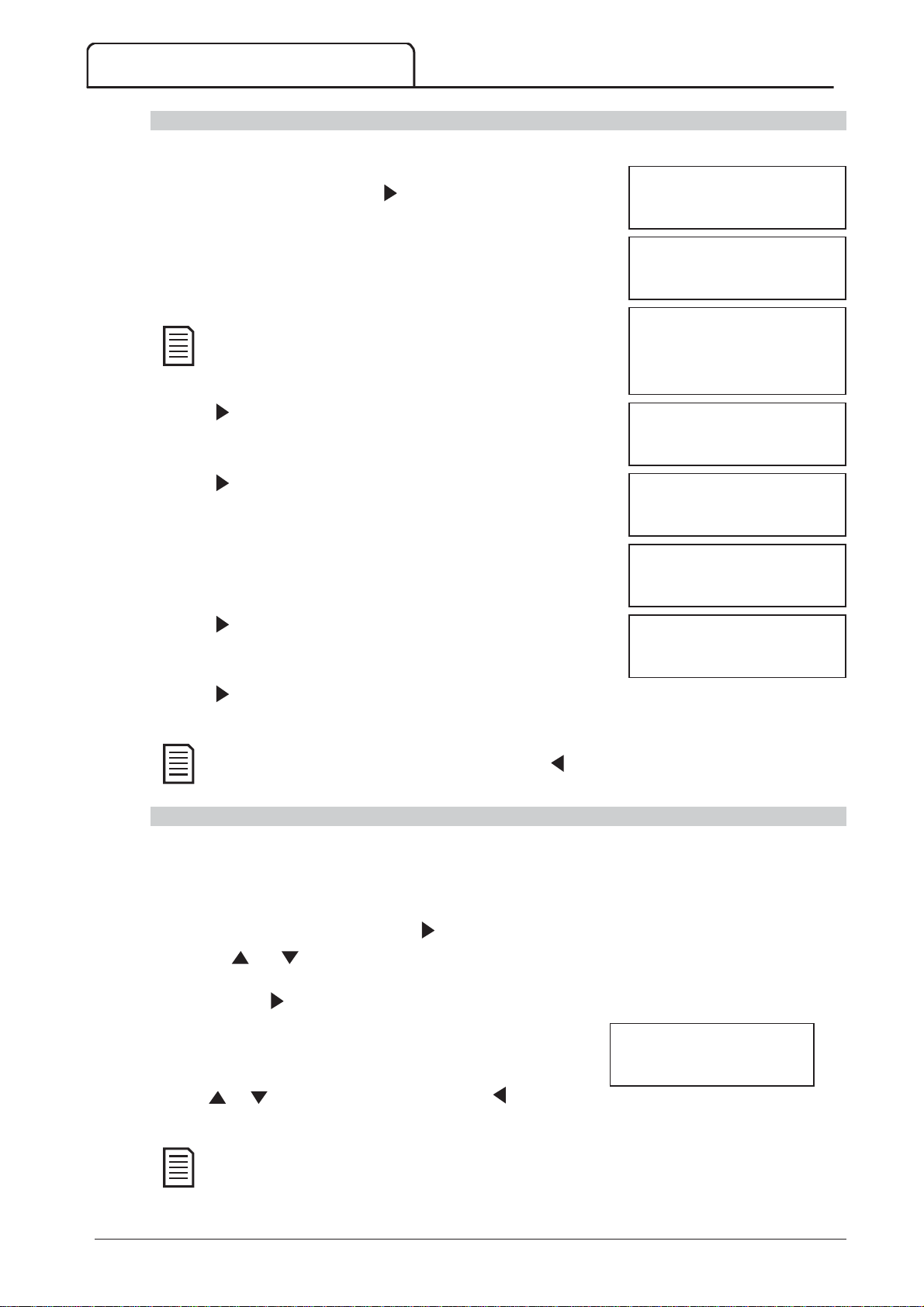
COMMISSIONING
START
STORE
NOTE
STORE
STORE
STOP
STORE
STORE
NOTE
protection simulation
NOTE
Run Simulation
To use the run simulation:
1. Open the Commissioning Menu.
2. Scroll to Run Simulation and press
3. Press S
checks and closes the main contactor relay. The Run LED flashes.
4. Press . The MVS simulates starting. The Run LED flashes.
5. Press . The MVS simulates running. The Run LED stays on without
flashing and the bypass contactor relay closes.
6. Press S
Run LED flashes and the bypass contactor relay opens.
or activate the start input. The MVS simulates its pre-start
If mains voltage is connected, an error message is shown. Remove
mains voltage and proceed to the next step.
or activate the stop input. The MVS simulates stopping. The
.
Run Simulation
Ready
Apply Start Signal
Run Simulation
Pre-Start Checks
S
to Continue
Run Simulation
ATTENTION!
Remove Mains Volts
to Continue
Run Simulation
Starting X:XXs
to Continue
Run Simulation
Running
Apply Stop Signal
Run Simulation
Stopping X:XXs
to Continue
7. Press . The Ready LED flashes and the main contactor relay opens.
8. Press to return to the commissioning menu.
Run simulation can be exited at any stage by pressing the
.
.
Protection Simulation
The p
associated control circuits are responding correctly.
To use the protection simulation:
1. Open the Commissioning Menu.
2. Scroll to Protection Simulation and press
3. Use the
simulate.
4. Press and hold
5. The screen is displayed momentarily. The soft starter's response
depends on the Protection Action setting (parameter group 16).
6. Use or to select another simulation, or press to exit.
and buttons to select the protection you want to
simulates activation of each protection mechanism to confirm that the soft starter and
.
to simulate the selected protection.
Run Simulation
Stopped
to Continue
0.0A
Tripped
Selected Protection
If the protection trips the soft starter, reset before simulating another protection. If the protection action is
set to 'Warn and Log', no reset is required.
58 MVS Panel User Manual 710-13937-00C
Page 60
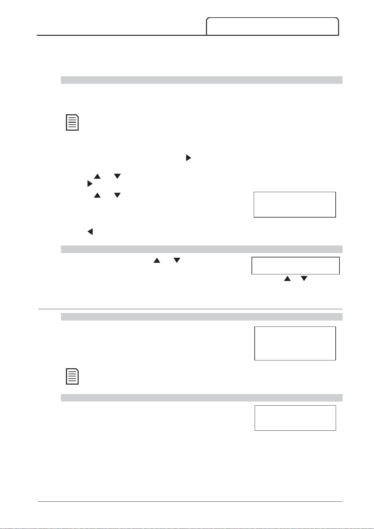
COMMISSIONING
STORE
output signal simulation
NOTE
NOTE
If the protection is set to 'Warn and Log', the warning message can be viewed only while the S
button is pressed.
If the protection is set to 'Log only', nothing appears on the screen but an entry will appear in the log.
Output Signal Simulation
The o
operating correctly.
To test operation of the flags (motor temperature and low/high current), set an output relay to the
appropriate function and monitor the relay's behaviour.
To use the output signal simulation:
1. Open the Commissioning Menu.
2. Scroll to Output Signalling Simulation and press
3. Use the
press
4. Use the
To confirm correct operation, monitor the state of the output.
and buttons to select a function to simulate, then
.
and buttons to turn the signal on and off.
simulates output signalling to confirm that outputs and associated control circuits are
.
Prog Relay A
Off
On
5. Press to return to the simulation list.
Analog Output Simulation
The analog output simulation uses the and buttons to change the
analog output current at terminals B10, B11 of the controller.
Attach an external current measuring device to terminals B10, B11 of the controller. Use the or button to
adjust the percentage value in the lower left hand corner of the display. The current measuring device should
indicate the same level of current as shown at the lower right corner of the display.
10.4 Input/Ouput Status
Temperature Sensors State
This screen shows the state of the motor thermistors and RTD/PT100s.
The use of RTDs is not supported by this product and this screen will always indicate 0 (ie Open) for
RTDs A->G.
Digital I/O State
This screen shows the current status of the digital inputs and outputs.
The top line of the screen shows the start, stop, reset and programmable inputs A and B, then '00'. The screen
shows input C23~C24 closed with all other inputs open.
The bottom line of the screen shows programmable output A, the fixed Run output, programmable outputs B and
C, then '000'. The screen shows all outputs open.
Analog Output
0% 4 mA
Temp Sensors State
Thermistor: O
RTDs A–>G:OOOOOOO
S = Shrt H=Hot C=Cld O=Opn
Digital I/O State
Inputs: 1000000
Outputs: 0000000
710-13937-00C MVS Panel User Manual 59
Page 61
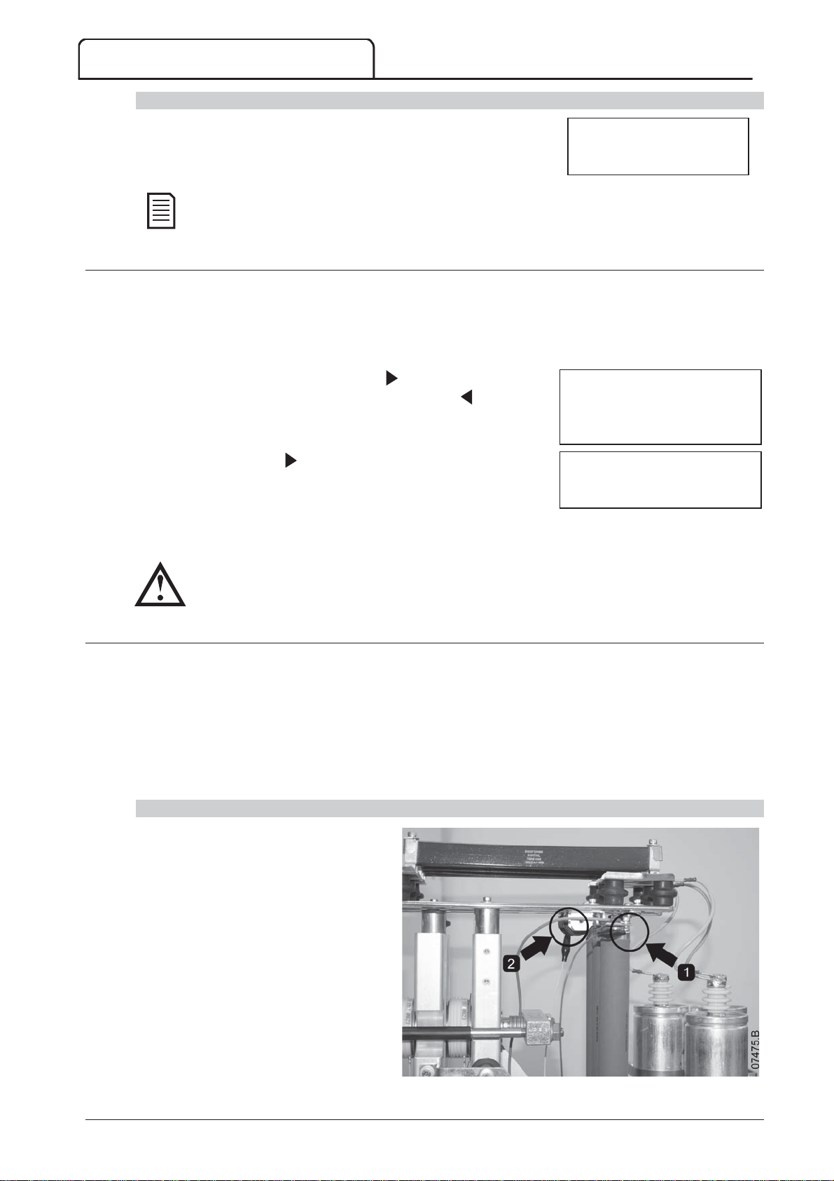
COMMISSIONING
NOTE
STORE
CAUTION
Analog I/O State
This screen shows the current status of the Analog I/O
Input is not supported by this product and this screen will always indicate Input: - - - - %
10.5 Reset Thermal Models
The MVS's advanced thermal modelling software constantly monitors the motor's performance. This allows the
MVS to calculate the motor's temperature and ability to start successfully at any time.
The thermal model for the active motor can be reset if required.
1. Open the Commissioning Menu.
2. Scroll to Reset Thermal Models and press
3. At the confirmation prompt press S
the action. You may have to enter your access code.
4. Select Reset and press .
Selecting Do Not Reset returns to previous screen.
When the thermal model has been reset, the screen will display a
confirmation message then return to the previous screen.
.
to confirm or to cancel
Analog I/O State
Input: ----%
Output A: 04.0mA
Reset Thermal Models
M1 X%
M2 X%
Store to Reset
Reset Thermal Models
Do Not Reset
Reset
Resetting the motor thermal model may compromise motor life and should only be done in the case of
emergency.
10.6 Low Voltage Test Mode
The MVS can be connected to a low voltage motor ( 500 VAC) for testing. This allows the user to thoroughly
test the soft starter and its associated power and control circuits. The low voltage test mode provides a means of
testing the soft starter's configuration without requiring a full medium voltage test facility.
For models V06 and higher, one non-conduction resistor assembly must be connected to each phase arm (three
assemblies are supplied with the soft starter). The non-conduction resistor assembly is not required for models
V02 ~ V04.
During the low voltage test, the soft starter's control input, relay output and protection settings can be tested. Low
voltage mode is not suitable for testing soft starting or soft stopping performance.
MVSxxxx-V06, V07
1. Clip one end of the resistor assembly to
the bolt on the non-conduction PCB.
The nonside of the phase arm, at the top of the
long round grading resistor (on the left
hand side of the phase arm when viewed
from the back). There is a small steel
bracket just in front of the PCB.
2. Pass the other end of the assembly
through the phase arm, in front of the
three grading resistors, and clip it to the
steel bracket in front of the grading
resistor on the other side of the phase
arm (this bracket looks the same as the
bracket in front of the non-conduction
PCB).
conduction PCB is located on the
60 MVS Panel User Manual 710-13937-00C
Page 62
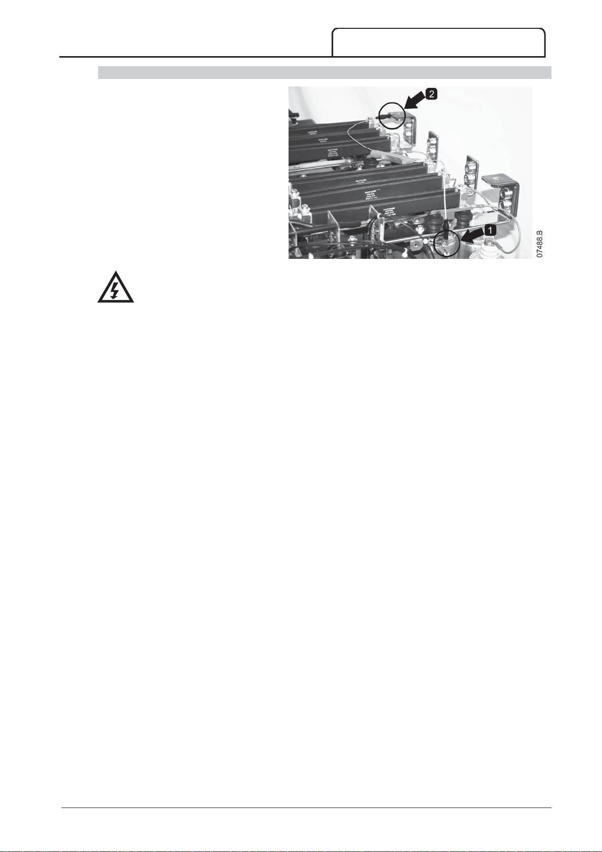
COMMISSIONING
WARNING
MVSxxxx-V13
1. Clip one end of the resistor assembly to
the bolt on the non-conduction PCB (do
not connect to earth bolt, ie
green/yellow wire). The
non-conduction PCB is located on the
side of the phase arm, at the top of the
long round grading resistor (on the left
hand side of the phase arm when
viewed from the back).
2. Pass the other end of the assembly over
the phase arms and clip it to the busbar
at the other side of the phase arm.
W
After low voltage mode testing, ensure that the non-conduction resistor assembly is removed from each
phase arm before connecting the soft starter to a medium voltage motor. If the non-conduction resistor
assemblies remain on the phase arms, the soft starter may suffer severe damage.
To operate the MVS in low voltage test mode:
2. Isolate the soft starter from the motor and the mains supply.
3. Connect one non-conduction resistor assembly to each phase arm.
4. Connect T1, T2, T3 of the soft starter to a three phase motor with full load current of 5 ~ 20 A. Connect L1,
L2, L3 of the soft starter to three phase mains supply with voltage less than 500 VAC (frequency 50 Hz or
60 Hz).
5. Set parameter
6. Switch on control and mains supply, and use the MVS to start the motor. The start command can be sent
from the controller or via the remote input. Monitor the soft starter's display and verify the line current and
voltage readings.
7. Stop and restart the motor several times to confirm correct and consistent operation.
8. When testing is complete, isolate the soft starter from the mains supply. Disconnect the soft starter from the
motor and then remove control voltage. Remove the non-conduction resistor assembly from each phase arm.
1A Motor Full Load Current
to the value shown on the motor name plate.
710-13937-00C MVS Panel User Manual 61
Page 63
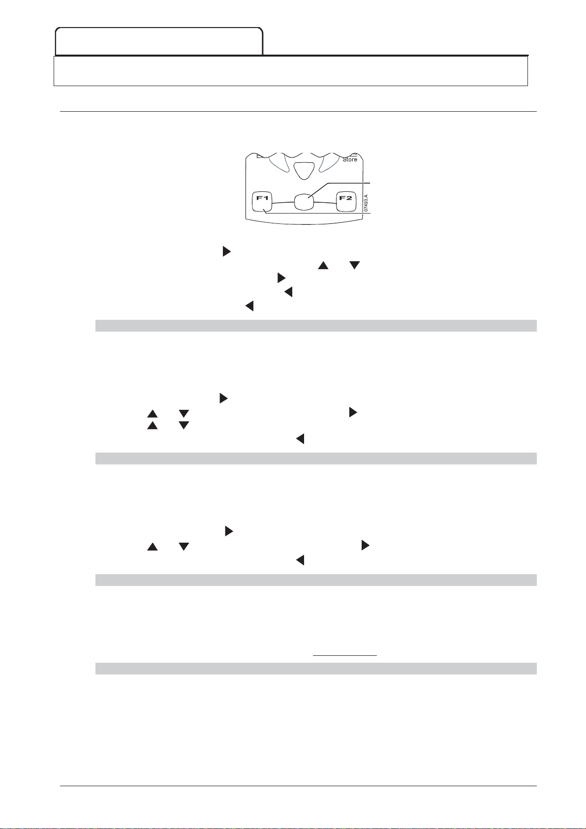
MONITORING
ALT
LOGS
ALT
LOGS
ALT
LOGS
ALT
LOGS
11 Monitoring
11.1 Logs Menu
The Logs Menu provides information on events, trips and starter performance.
To open the Logs Menu, press A
then L
while viewing the metering screens.
Logs
To navigate through the Logs Menu:
to open a log, press the
to scroll through the entries in each log, press the
to view details of a log entry, press the
to return to the previous level, press the
to close the Logs Menu, press
button.
repeatedly.
Alt
button.
button.
Tools
L
and buttons.
Trip Log
The Trip Log stores details of the eight most recent trips, including the date and time the trip happened. Trip 1 is
the most recent and trip 8 is the oldest stored trip.
To open the Trip Log:
1. Press A
2. Scroll to Trip Log and press
3. Use the
4. Use the
To close the log and return to the main display, press
then L
and buttons to select a trip to view, and press to display details.
and buttons to scroll through available details.
to open the Logs.
.
repeatedly.
Event Log
The Event Log stores time-stamped details of the starter's 99 most recent events (actions, warnings and trips),
including the date and time of the event. Event 1 is the most recent and event 99 is the oldest stored event.
To open the Event Log:
1. Press A
2. Scroll to Event Log and press
3. Use the
To close the log and return to the main display, press
then L
and buttons to select an event to view, and press to display details.
to open the Logs.
.
repeatedly.
Starter Trip and Event Logger Software
The Starter Trip and Event Logger Software allows you to download the trip and event logs from the soft starter,
for separate analysis.
The software is compatible with all AuCom medium voltage soft starters using control software version 1.29 or
later.
For further information, or to download the software, visit www.aucom.com.
Performance Counters
The performance counters store statistics on the starter's operation:
Hours run (lifetime and since counter last reset)
Number of starts (lifetime and since counter last reset)
Motor kWh (lifetime and since counter last reset)
Number of times the thermal model has been reset
The resettable counters (hours run, starts and motor kWh) can only be reset if the
15B) is set to Read & Write.
62 MVS Panel User Manual 710-13937-00C
Adjustment Lock
(parameter
Page 64
To view the counters:
STORE
STORE
1. Open the Logs Menu.
.
(enter access code if required) then use the button to select Reset.
2. Scroll to Counters and press
3. Use the
and buttons to scroll through the counters. Press to view details.
4. To reset a counter, press S
Press
to confirm the action.
To close the counters and return to the main display, press the
MONITORING
repeatedly.
710-13937-00C MVS Panel User Manual 63
Page 65
OPERATION
CAUTION
LCL/RMT
STOP
START
STOP
RESET
STOP
RESET
12 Operation
C
We recommend testing the soft starter's setup on a low voltage motor before beginning operation on a
medium voltage motor. This allows the operator to test that the soft starter is correctly connected to
the auxiliary equipment.
12.1 Start, Stop and Reset Commands
The soft starter can be controlled in three ways:
using the buttons on the controller
via remote inputs
via a serial communication link
The L
(via the remote inputs).
The Local LED on the controller is on when the soft starter is in local control mode and off when the soft starter is
in remote control mode.
Control via the fieldbus communication network is always enabled in local control mode, and can be enabled or
disabled in remote control mode (parameter 6R
network requires an optional communication module.
The S
button controls whether the MVS will respond to local control (via the controller) or remote control
button on the controller is always enabled.
Comms in Remote
). Control via the serial communication
12.2 Using the Soft Starter to Control a Motor
To soft start the motor, press the S
will start using the start mode selected in parameter 2A.
To stop the motor, press the S
stop using the stop mode selected in parameter 2H.
To reset a trip on the soft starter, press the R
To stop the motor with a coast to stop, regardless of the setting of parameter 2H
and
contactor, and the motor will coast to stop.
buttons at the same time. The soft starter will remove power from the motor and open the main
button on the controller or activate the Start remote input. The motor
button on the controller or activate the Stop remote input. The motor will
button on the controller or activate the Reset remote input.
Stop Mode
, press the local S
64 MVS Panel User Manual 710-13937-00C
Page 66
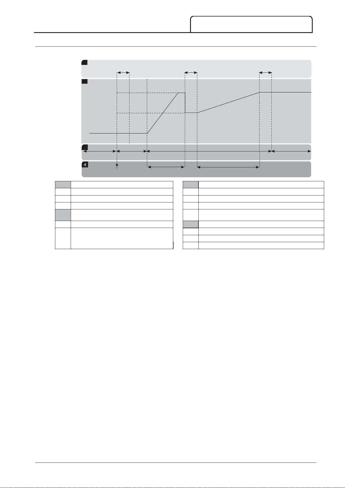
12.3 Using the MVS to Control a Slip-Ring Motor
1
3
2
4
The MVS can be used to control a slip-ring motor, using rotor resistance.
1
t1 t2 t3
2
V1
V2
3
S
1
S2 S3 S4
P1 P2 P3
OPERATION
03986.C
Sub-states
States
t1 Main contactor close time S1 Ready
t2 Rotor resistance contactor close time S2 Pre-start tests
t3 Bypass contactor close time S3 Starting
Output voltage S4 Running
V1 100% voltage
Phases of operation
V2 Slip-ring retard voltage P1 Start command
P2 Rotor resistance current ramp
P3 Shorted rotor current ramp
710-13937-00C MVS Panel User Manual 65
Page 67
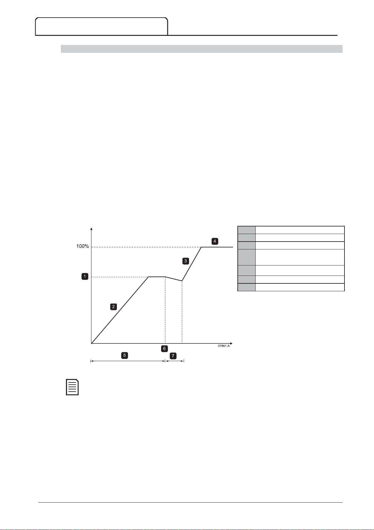
OPERATION
1
2
3
4
5
6
7
NOTE
Commissioning
1. Configure the MVS as follows:
Parameter settings:
Parameter 7A
Select 'Changeover Contactor'
Parameter 7B
Set this to the maximum time (5m:00s).
Parameter 12A
Select 'Dual Ramp' (for slip-ring induction motor control)
Parameter 12C
Default setting is 150 milliseconds. Set this to a value just greater than the changeover contactor
(K3) pole closing time.
Parameter 12D
Default setting is 50%. Set this parameter to a value which is high enough to cause the motor to
instantly accelerate once the rotor resistance (R1) has been bridged out and low enough to avoid a
motor current pulse.
2. Start the motor under normal load conditions and record the time it takes to reach a constant speed with
external rotor resistance (R1) in the circuit. Stop the motor soon after a constant speed has been reached.
Change parameter 7B to the recorded time value.
3. Start the motor under normal load conditions and monitor the motor speed behaviour and motor current
when the changeover contactor (K3) switches in to short-out the rotor resistance (R1)
If the motor does not start to accelerate immediately after changeover, increase the setting of parameter 12D.
If there is a pulse in motor current immediately after changeover, reduce the setting of parameter 12D.
Relay A Function
Relay A On Delay
Motor Data-1 Ramp
Changeover Time
Slip Ring Retard
R1 constant speed
First ramp
Second ramp
Run mode (I < 120% FLC)
3
Parameter 7B
K3 closes
Parameter 12C
Speed
Time
For this installation to function correctly, only use the constant current start method (parameter 2A
Mode
). To use the secondary motor settings, parameter 12B
Ramp'.
Motor Data-2 Ramp
must be set to 'Dual
Start
66 MVS Panel User Manual 710-13937-00C
Page 68
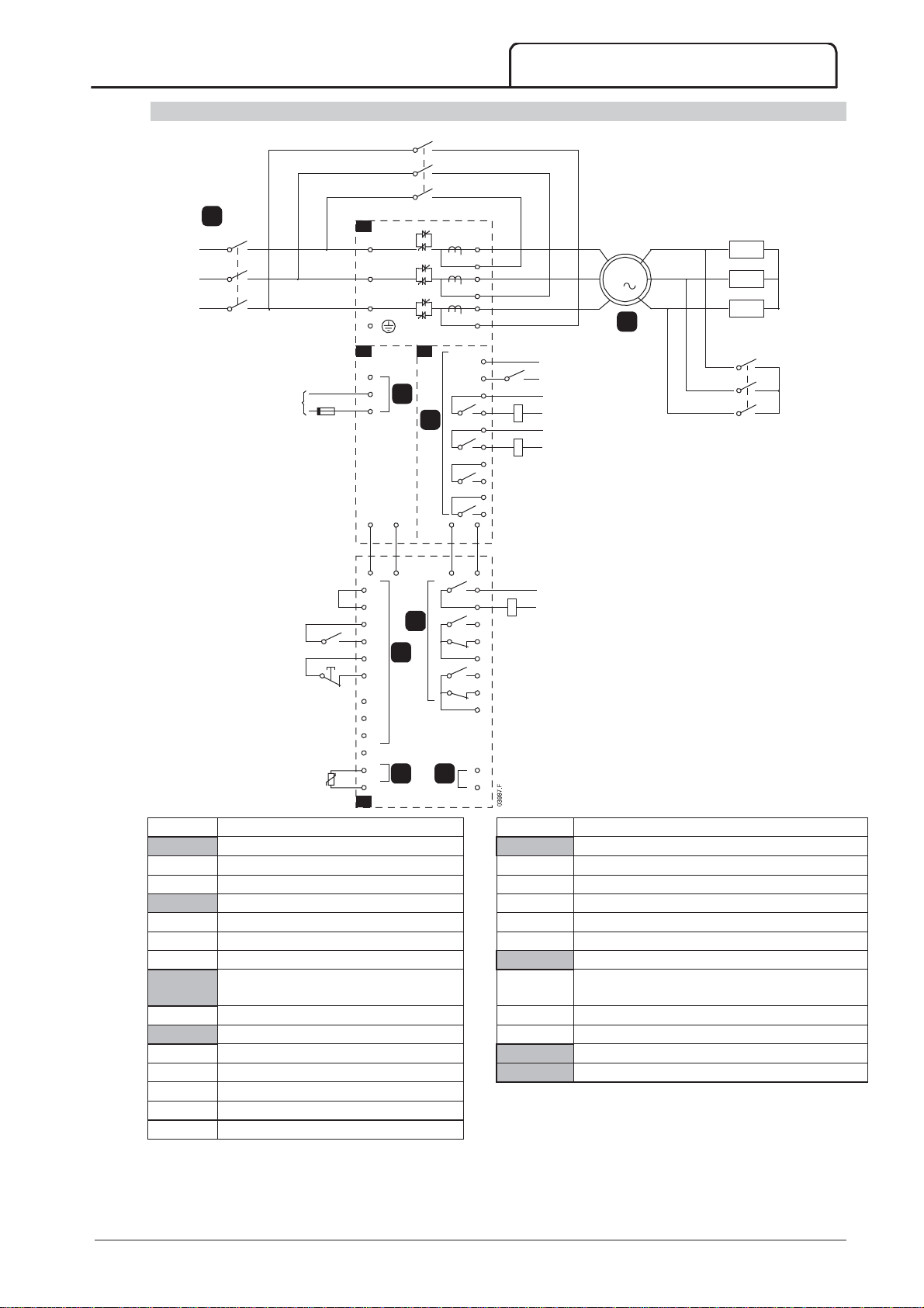
Slip-Ring Motor Connection
A1
A4
1
5
2
A2
6
3
A3
4
7
8
OPERATION
K2
1
K1
220~240VAC
+10
-15
A1
L1
L2
L3
E
A3A2
A1
A2
3
A3
F1
A11 A12
A11 A12
C23
C24
C31
S1
S2
C32
C41
C42
C53
C54
C63
C64
B4
B5
A4
6
5
7 8
4
TX RX
RX TX
T1
T1B
T2
T2B
T3
T3B
C73
C74
K2
13
14
23
24
33
34
43
44
(Bk)(Wh)
(Wh)(Bk)
43
44
54
52
51
64
62
61
B10
+
B11
-
K1
K2
K3
3
M
2
R1
K3
Power assembly A
3 Phase 50/60 Hz Supply
Controller
Remote control inputs
K1 Main contactor C23~C24 Control Input - Start
K2 Bypass contactor C31~C32 Control Input - Stop
Motor C41~C42 Control Input - Reset
R1 Slip-ring rotor resistance C53~C54 Control Input - Programmable input A
K3 Changeover contactor C63~C64 Control Input - Programmable input B
Control voltage terminals
Programmable outputs
Control supply 43, 44 Relay output A
Functionality = Changeover contactor
Power interface board 51, 52, 54 Relay output B
Relay outputs 61, 62, 64 Relay output C
C73~C74 Bypass contactor feedback signal
13~14 Main contactor K1
Motor thermistor input
Analog output
23~24 Bypass contactor K2
33~34 Run relay output
43~44 Fan control output
710-13937-00C MVS Panel User Manual 67
Page 69
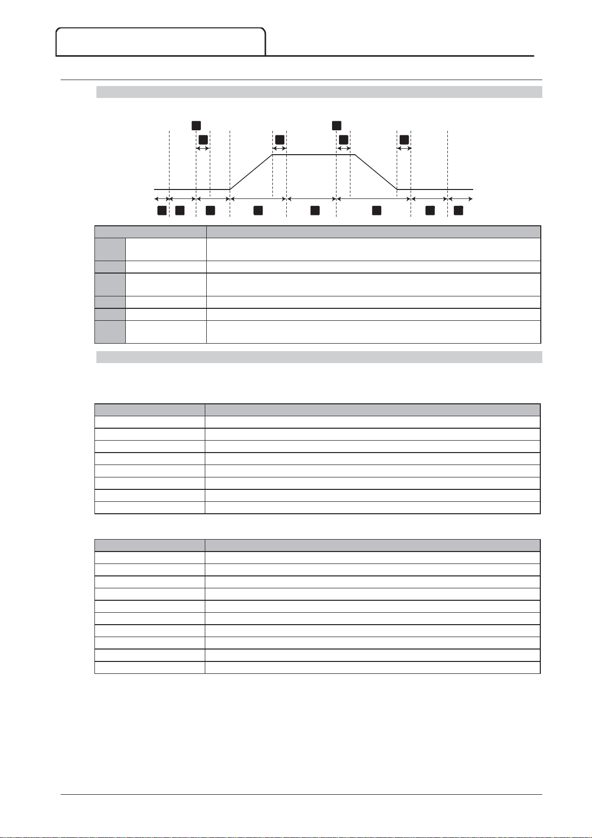
OPERATION
State
Starter actions
1
2
3
4
5
6
State
Function
State
Starter action
12.4 Operating States
Start and Run States
The MVS soft starter has six operating states, and performs the following actions in each state:
a d
b
c fe
321 4 65
1 2
Not ready Control power is on and the starter performs system checks. The starter may be
waiting for the motor to cool before allowing a start.
Ready The starter is initialised and waiting for a start command.
Pre-start checks A start command has been received (a). The main contactor closes (b) and the starter
performs connection checks.
Starting The starter ramps the SCRs up to full conduction and closes the bypass contactor (c).
Running The motor is running normally.
Stopping A stop command has been received (d). The starter opens the bypass contactor (e),
ramps the SCRs down to no conduction, then opens the main contactor (f).
Trip States
The starter's response to a trip depends on the starter's state when the trip occurs.
Trip while starting (bypass contactor not yet closed)
Not ready Perform system checks.
Ready Wait for start command.
Start command received Main contactor closes.
Pre-Start Checks Perform connection checks.
Starting Ramp up SCR firing angles.
Trip command Turn SCRs off then open main contactor.
Tripped Wait for reset command.
Reset command received Trip cleared and starter returns to Not Ready state or Ready state.
07717.A
Trip while running (bypass contactor closed)
Not ready Perform system checks.
Ready Wait for start command.
Start command received Main contactor closes.
Pre-Start Checks Perform connection checks.
Starting Ramp up SCR firing angles.
Full conduction SCRs at 100% conduction. Verify current is < 120% FLC then close bypass contactor.
Running Normal motor run state (bypassed mode).
Trip command Open bypass contactor. Turn SCRs off then open main contactor.
Tripped Wait for reset command.
Reset command received Trip cleared and starter returns to Not Ready or Ready state.
Instantaneous Overcurrent Stage 2 trip
The main contactor opens immediately, regardless of the starter's state.
68 MVS Panel User Manual 710-13937-00C
Page 70
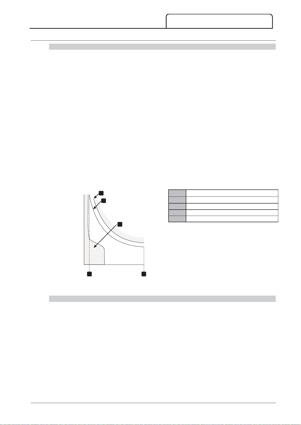
12.5 Motor Protection
1
2
3
4
5
Motor, System and Soft Starter Protection Mechanisms
The MVS incorporates extensive protection features to ensure safe operation of the motor, system and soft starter.
Most protection features can be customised to suit the installation. Use parameter group 4 Protection Settings to
control the situation where the protections will activate and parameter group 16 Protection Action to select the
soft starter's response. The default response is to trip the soft starter.
Protection Coordination
Check protection settings on the supply side of the starter to ensure correct coordination with the parameters of
the soft starter. .
When using fuse and main contactors, set the upstream circuit breaker protection parameters according to the
ratings for fuse and contactor. The contactor must not open if the current is above its maximum breaking current
value. The fuse must act first or the upstream breakers instantaneous trip level must be less than the contactor's
maximum breaking current level.
If using circuit breakers only, set the soft starter's maximum instantaneous trip time < 150 ms. Always use a suitable
external protection relay with a circuit breaker to ensure instantaneous overcurrent trip functionality.
Voltage must not be continuously maintained on the phase arms while the motor is off. Short circuit protective
equipment must be installed in all cases.
Motor Overload Protection
The MVS offers thermal model motor overload protection which monitors the performance of the motor and
calculates its temperature in all states. This protection is based on the motor information programmed in
parameter groups 1 and 9, and the thermal model adjusts itself according to the motor's recent operating history
(including temperature rise from previous operation).
OPERATION
3
4
Motor service factor
Locked rotor current
Motor failure curve
Motor thermal model protection curve
Typical motor operating current
5
Time
04013.C
1
2
Current
Motor Thermal Model Protection Set-up
To enable motor and starter protection using the motor thermal model, the soft starter must be programmed with
accurate information on the motor's characteristics.
1. Set parameters 1B
the motor datasheet.
2. Use instantaneous overcurrent protection (parameters 4E, 4F) to provide protection for locked rotor
situations. Refer to individual parameters for details.
3. Use instantaneous overcurrent protection stage 2 (parameters 4U, 4V) to trip circuit breaker or main contactor
in the event of extreme overcurrent situations.
Locked Rotor Time
, 1C
Locked Rotor Current
and 1D
Motor Service Factor
according to
710-13937-00C MVS Panel User Manual 69
Page 71
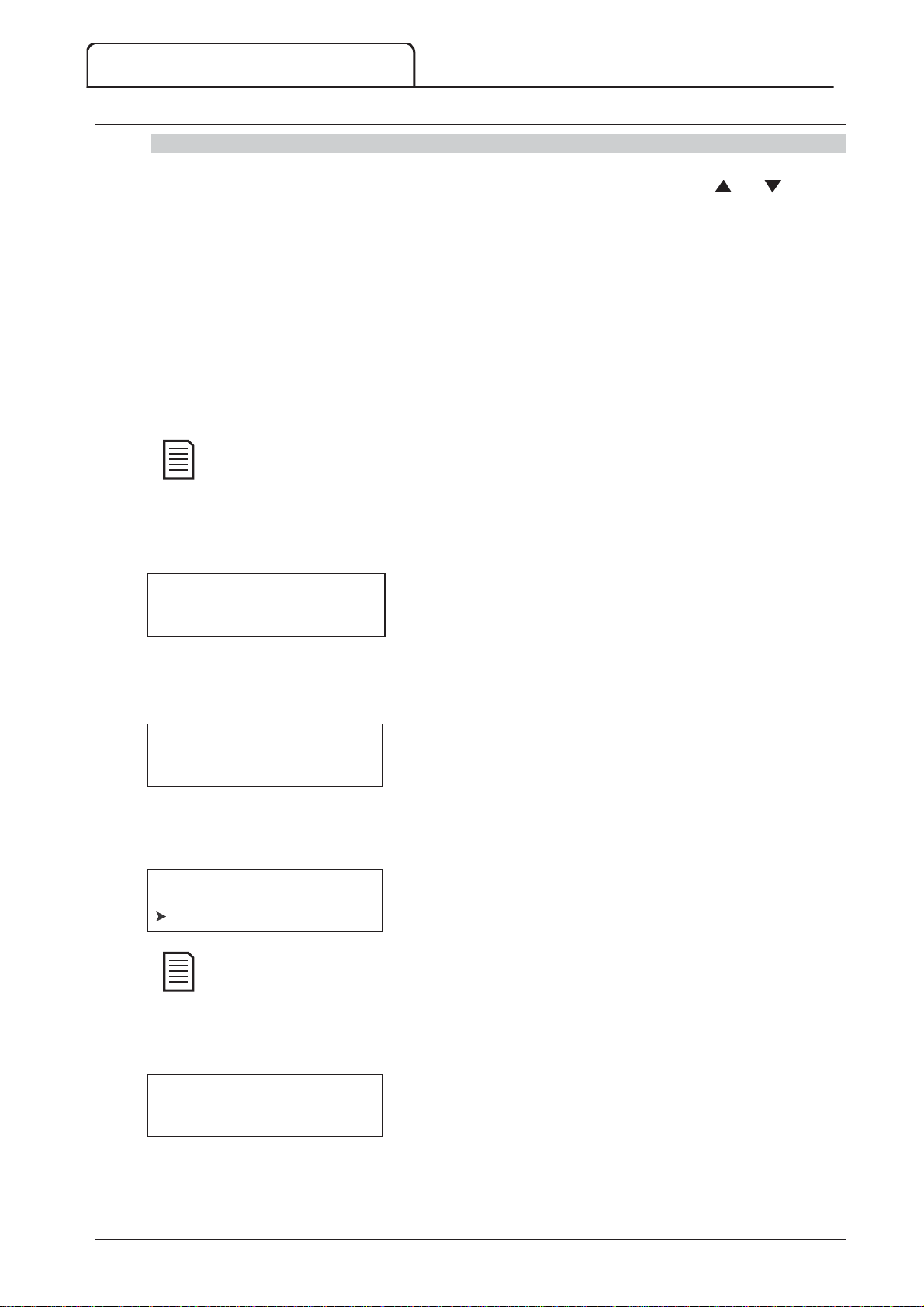
OPERATION
NOTE
NOTE
12.6 Operating Feedback
Displays
The controller displays a wide range of performance information about the soft starter. The top half of the screen
shows real-time information on current or motor power (as selected in parameter 8D). Use the
buttons to select the information shown on the bottom half of the screen.
Starter status
User programmable screen
Motor temperature
Current
Motor power
Voltage
Last start information
Date and time
Performance graphs
SCR conduction
Screens shown here are with the default settings.
and
Starter Status
The starter status screen shows details of the starter's operating status, including motor current, power and
temperature.
0A
Ready
M1 000% 000.0kW
Programmable screen
The MVS's user-programmable screen can be configured to show the most important information for the particular
application. Use parameters 8E to 8H to select which information to display.
0A
Ready
00000 kWh 00000hrs
Motor Temperature
The temperature screen shows which motor data set is in use, and the temperature of the motor as a percentage
of total thermal capacity.
0A
Primary Motor Set
M1 000% M2 000%
M2 xxx% temperature is not applicable to this product.
Current monitoring screen
The current screen shows real-time line current on each phase.
0A
Phase Currents (Gnd Crnt XX.XA)
000.0A 000.0A 000.0A
70 MVS Panel User Manual 710-13937-00C
Page 72
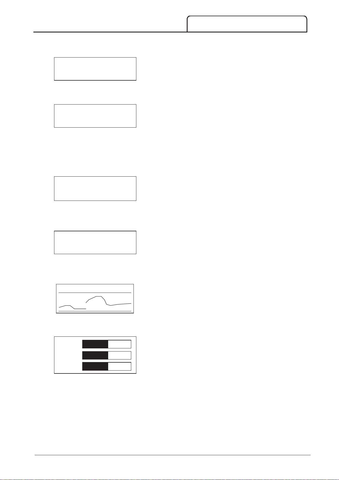
Motor Power
The motor power screen shows motor power (kW, HP and kVA) and power factor.
0A
000.0kW 0000HP
0000kVA -. - - pf
Voltage
The voltage screen shows real-time line voltage across each phase.
0A
Line Voltages
00000 00000 00000
Last Start Information
The last start information screen shows details of the most recent successful start:
start duration (seconds)
maximum start current drawn (as a percentage of motor full load current)
calculated rise in motor temperature
0A
Last start 000 s
000 % FLC Temp 0%
OPERATION
Date and Time
The date/time screen shows the current system date and time (24 hour format). For details on setting the date
and time, refer to
Set Date and Time
on page 57.
0A
DD MMM YYYY
HH:MM:SS
Performance Graph
The performance graph provides a real-time display of operating performance. Use parameters 8I~8L to select
which information to display.
0000 A 0%-400%
10166.A
SCR Conduction Bargraph
The SCR conduction bargraph shows the level of conduction on each phase.
L1 Cond
L2 Cond
L3 Cond
710-13937-00C MVS Panel User Manual 71
Page 73
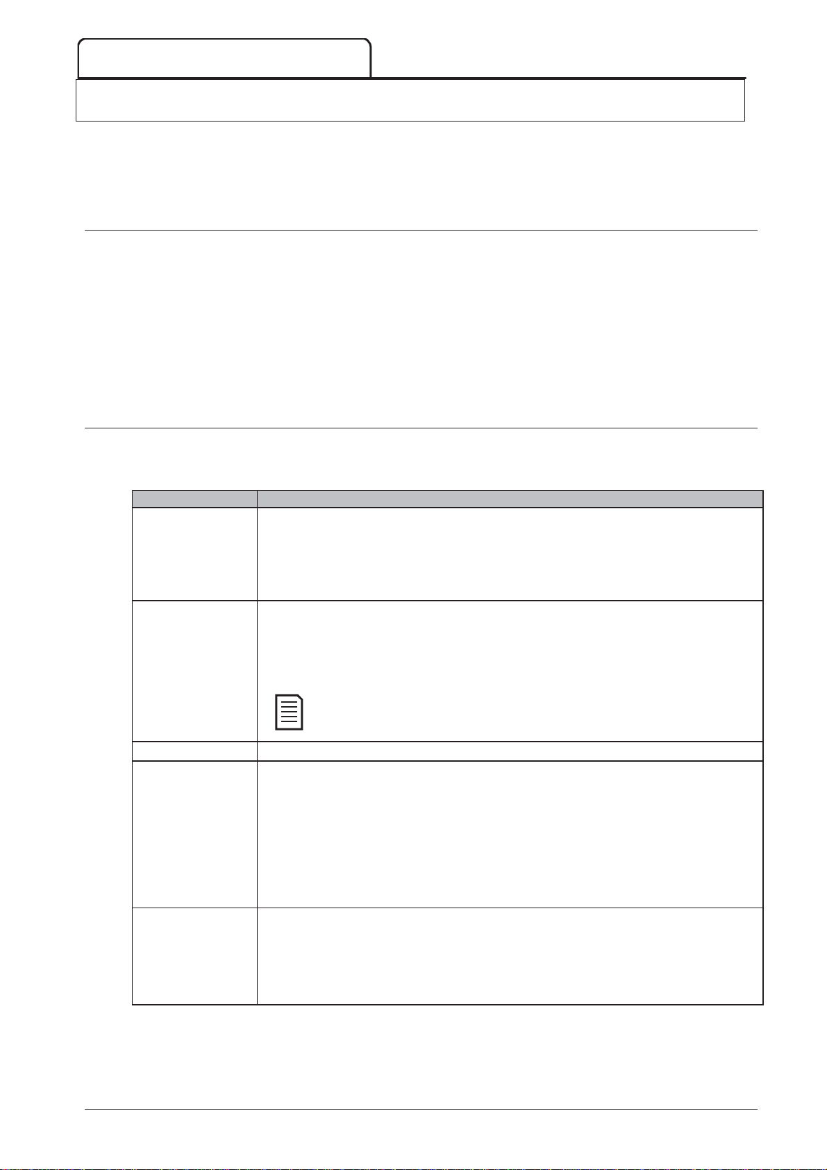
TROUBLESHOOTING
RESET
Display
Possible cause/Suggested solution
NOTE
13 Troubleshooting
The MVS provides extensive information to help the operator diagnose and remedy any operating difficulties.
In addition to the motor and load protection features already described, the MVS reports in detail on the starter's
own state. Any internal failure will cause the soft starter to trip, and full details will be recorded in the Trip Log and
Event Log.
13.1 Protection Responses
When a protection condition is detected, the MVS will write this to the event log and may also trip or issue a
warning. The soft starter's response depends on the Protection Action setting (parameter group 16).
Some protection responses cannot be adjusted by the user. These trips are usually caused by external events (such
as phase loss) or by a fault within the soft starter. These trips do not have associated parameters and cannot be set
to Warn or Log.
If the MVS trips you will need to identify and clear the condition that triggered the trip, then reset the soft starter
before restarting. To reset the starter, press the
input.
If the MVS has issued a warning, the soft starter will reset itself once the cause of the warning has been resolved.
13.2 Trip Messages
This table lists soft starter's protection mechanisms and the probable cause of the trip. Some of these can be
adjusted using parameter group 4 Protection Settings and parameter group 16 Protection Action, other settings are
built-in system protections and cannot be set or adjusted.
R
button on the controller or activate the Reset remote
Battery/clock
Bypass fail (bypass
contactor)
Controller
Current imbalance
A verification error has occurred on the real time clock, or the backup battery voltage is low. If
the battery is low and the power is off, date/time settings will be lost. The MVS will continue
to soft start and soft stop correctly. Reprogram the date and time.
The battery is not removable. In order to replace the battery, the main control PCB must be
replaced.
Related parameters: 16M
The bypass contactor has welded closed or is not operating correctly. There may be a
problem with the control circuit or the contactor coil.
Check the condition of the bypass contactor's main poles. Check the operation of the
contactor control circuitry and contactor coil.
This trip is not adjustable.
You can use the Run Simulation to check the bypass contactor's operation
without mains voltage connected.
This is a name selected for a programmable input. Refer to Input A trip.
Current imbalance can be caused by problems with the motor, the environment or the
installation, such as:
An imbalance in the incoming mains voltage
A problem with the motor windings
A light load on the motor
A phase loss on input terminals L1, L2 or L3 during Run mode
An SCR that has failed open circuit. A failed SCR can only be definitely diagnosed by replacing
the SCR and checking the starter's performance.
Related parameters: 4H, 4I, 16E
EEPROM fail An error occurred loading data from the EEPROM to RAM when the controller powered
up.
"Load User Set" has been selected but no saved file is available.
Reset the fault and then reload the default settings. If the problem persists, contact your local
distributor.
Related parameters: None
72 MVS Panel User Manual 710-13937-00C
Page 74
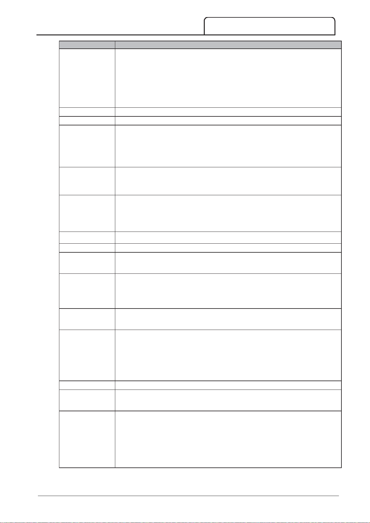
TROUBLESHOOTING
Display
Possible cause/Suggested solution
D
Excess start time
Feeder Prot
Field Trip
Frequency
Ground fault
Heatsink
overtemperature
High Level
P
The motor was unable to accelerate to full speed in the time allowed.
Excess start time trip can occur in the following conditions:
parameter 1A
parameter 2D
parameter 2B
Time
setting
The motor may have experienced an abnormal increase in loading or might be jammed.
Related parameters:1A, 2A-2D, 4A, 16B
This is a name selected for a programmable input. Refer to Input A trip.
This is a name selected for a programmable input. Refer to Input A trip.
The mains frequency has gone beyond the specified range.
Check for other equipment in the area that could be affecting the mains supply, particularly
variable speed drives and switch mode power supplies (SMPS).
If the MVS is connected to a generator set supply, the generator may be too small or could
have a speed regulation problem.
Related parameters: 4J, 4K, 4L, 16F
Ground current (monitored through a dedicated current transformer) has exceeded the
selected level. Test the insulation of the output cables and the motor. Identify and resolve the
cause of any ground fault.
Related parameters: 4O, 4P, 16N
The soft starter is operating at a dangerously high temperature.
Check if ventilation and cooling are adequate.
Reduce the number of consecutive starts by increasing the value set in parameter 4M
Restart Delay
Related parameters: 4M
This is a name selected for a programmable input. Refer to Input A trip.
Motor Full Load Current
Current Limit
Start Ramp Time
.
has been set too low
has been set greater than the setting for 4A
is not appropriate for the motor
Excess Start
High Pressure
Input A trip
Instantaneous
overcurrent
Instantaneous
overcurrent S2
Int Comms Fail
Interlock Trip
Internal fault 94 ~
Internal fault 98
Internal fault 99 Internal fault 101
This is a name selected for a programmable input. Refer to Input A trip.
The soft starter's programmable input is set to a trip function and has activated. Resolve the
trigger condition.
Related parameters: 6A, 6B, 6C, 6D, 6E, 6F, 6G, 6H, 6I, 6J, 16G, 16H
There has been a sharp rise in motor current, probably caused by a locked rotor condition
(shearpin) while running. This may indicate a jammed load.
A trip may also occur when a medium level fault current has been detected. This may indicate
a system short circuit.
Related parameters: 4E, 4F, 16D
There has been a sharp rise in output current, possibly caused by a short circuit condition.
Identify and resolve the cause of the fault.
Related parameters: 4U, 4V, 16D
Communication has failed between the controller and the power interface board.
Check that the controller is receiving control voltage within the specified range (terminals
A11, A12).
Check that the fibre-optic cables between the controller and the interface board are firmly
connected.
Check that each fibre-optic cable is emitting light at the Rx end.
This trip is not adjustable.
This is a name selected for a programmable input. Refer to Input A trip.
There has been an internal communication error within the soft starter. Remove then restore
control power.
This trip is not adjustable.
There is a problem with the non-conduction fibre-optic connections. Internal Fault 99
corresponds to phase 1, Internal Fault 100 corresponds to phase 2, Internal Fault 101
corresponds to phase 3.
Check that the fibre-optic cable is properly connected between the non-conduction PCB
on the phase arm and the non-conduction readback connector on the power interface
board.
If the problem persists, replace the fibre-optic cable.
This trip is not adjustable.
710-13937-00C MVS Panel User Manual 73
Page 75
TROUBLESHOOTING
Display
Possible cause/Suggested solution
D
Internal fault 104
Internal fault 105
Internal fault 106
Internal fault X
L1 phase loss
L2 phase loss
L3 phase loss
L1-T1 shorted
L2-T2 shorted
L3-T3 shorted
Low Control Volts
Low Level
Low Pressure
Motor connection
Motor Connection
Tx
Motor overload
Motor Prot
Motor Temp
P
The power fail input is open circuit.
Check that control voltage is available.
There may be a wiring fault.
This trip is not adjustable.
The power interface board is faulty or damaged. Replace the board.
This trip is not adjustable.
The selected configuration for the CT ratio selection switches on the power interface board is
not valid.
Check the DIP switch settings on the interface PCB. Refer to
This trip is not adjustable.
The MVS has tripped on an internal fault. Contact your local supplier with the fault code (X).
Related parameters: None
During pre-start checks the starter has detected a phase loss as indicated.
In run state, the starter has detected that the current on the affected phase has dropped below
2% of the programmed motor FLC for more than 1 second, indicating that either the incoming
phase or connection to the motor has been lost.
Check the supply and the input and output connections at the starter and at the motor end.
Phase loss can also be caused by a failed SCR, particularly an SCR that has failed open circuit.
A failed SCR can only be definitely diagnosed by replacing the SCR and checking the starter's
performance.
Related parameters: None
During prestart checks the starter has detected a shorted power assembly or a short within the
bypass contactor as indicated.
This trip is not adjustable.
Control voltage to the controller has dropped below the required level.
This trip is not adjustable.
This is a name selected for a programmable input. Refer to Input A trip.
This is a name selected for a programmable input. Refer to Input A trip.
There is a problem with the soft starter's connection to the motor. If only one phase is
affected, the error message will indicate which phase (T1, T2, T3).
Ensure the motor is connected to terminals T1, T2, T3 using in-line (three wire)
connection. The MVS does not support inside delta (six wire) connection.
Check that the fibre-optic cables between the power interface board and the MVS are
firmly connected.
Check each output phase of the soft starter for power circuit continuity.
This trip will also occur when there is a phase imbalance across the soft starter’s input terminals
L1, L2, L3, during starting and stopping.
Related parameters: None
Where 'X' is 1, 2 or 3.
The motor is not connected correctly to the soft starter.
Check individual motor connections to the soft starter for power circuit continuity.
Check connections at the motor terminal box.
This trip is not adjustable.
Related parameters: None
The motor has reached its maximum thermal capacity. Overload can be caused by:
The soft starter protection settings not matching the motor thermal capacity
Excessive starts per hour
Excessive throughput
Damage to the motor windings
Resolve the cause of the overload and allow the motor to cool.
Related parameters: 1A, 1B, 1C, 1D, 9B, 16A
This is a name selected for a programmable input. Refer to Input A trip.
This is a name selected for a programmable input. Refer to Input A trip.
Ground Current
.
74 MVS Panel User Manual 710-13937-00C
Page 76
TROUBLESHOOTING
Display
Possible cause/Suggested solution
D
Motor thermistor
Network
communication
(between module
and network)
No Flow
Overvoltage
Phase sequence
PLC
Power loss
Pump Fault
Starter
communication
(between module
and soft starter)
Starter Disable
Undercurrent
Undervoltage
Vibration
VZC Fail Px
P
The external resistance across the motor thermistor input (terminals B4, B5) has exceeded
2.4 kɏ.
If the starter tripped at power-up, no thermistor is present at terminals B4, B5. If you are
not using a thermistor, you must attach a link across terminals B4-B5.
If the starter tripped during operation, the temperature of the motor winding has
increased. Resolve the cause of the overheating.
Related parameters: 16I
The network master has sent a trip command to the starter, or there may be a network
communication problem.
Check the network for causes of communication inactivity.
Related parameters: 16K
This is a name selected for a programmable input. Refer to Input A trip.
There has been a voltage surge on the mains. Causes can include problems with a transformer
tap regulator or off-loading of a large transformer load.
Check that the starter is configured appropriately for local conditions.
Monitor the mains voltage to determine the cause of the voltage fluctuation, and resolve
the cause.
Related parameters: 4S, 4T, 16W
The phase sequence on the soft starter's input terminals (L1, L2, L3) is not valid.
Check the phase sequence on L1, L2, L3 and ensure the setting in parameter 4G is suitable for
the installation.
Related parameters: 4G
This is a name selected for a programmable input. Refer to Input A trip.
The starter is not receiving mains supply on one or more phases when a start command is
given.
Check that the main contactor closes when a start command is given, and remains closed
until the end of a soft stop.
Check MVS fuses and confirm that all three mains supply phases are present.
This trip is not adjustable.
This is a name selected for a programmable input. Refer to Input A trip.
There could be a problem with the connection between the soft starter and the optional
communications module. Remove and reinstall the module. If the problem persists, contact
your local distributor.
The communications module has been powered down while the soft starter remains powered
up.
Related parameters: 16J
This is a name selected for a programmable input. Refer to Input A trip.
The motor has experienced a sharp drop in current, caused by loss of load. Causes can
include broken components (shafts, belts or couplings), or a pump running dry.
Related parameters: 4C, 4D, 16C
Mains voltage has fallen below the level selected in parameter 4Q. Causes can include an
undersized supply or adding a large load to the system.
Check that the starter is configured appropriately for local conditions.
Monitor the mains voltage to determine the cause of voltage fluctuation.
Related parameters: 4Q, 4R, 16V
This is a name selected for a programmable input. Refer to Input A trip.
Where 'X' is 1, 2 or 3.
The voltage detection system has failed.
The voltage dividing resistors have failed or the power interface board may be faulty.
Contact AuCom for advice.
710-13937-00C MVS Panel User Manual 75
Page 77
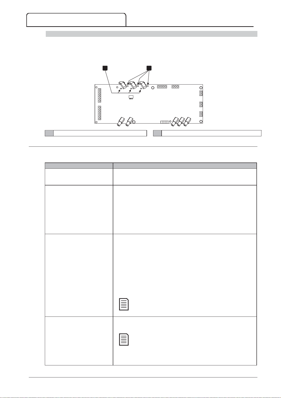
TROUBLESHOOTING
Symptom
Probable Cause
START
RESET
LCL/RMT
LCL/RMT
NOTE
LCL/RMT
NOTE
LED locations
The non-conduction and firing LEDs are located on the power interface PCB. The non-conduction LEDs should
dim during starting, and should be off when the bypass contactor closes. The firing LEDs should be on during
starting, and off just before the bypass contactor closes and the soft starter enters run mode.
The gate drive adaptor, gate drive and gate drive firing PCBs are located on individual phase arm power assemblies.
1 2
11Non-conduction LEDs (green) 22Firing LEDs (red)
13.3 General Faults
This table describes situations where the soft starter does not operate as expected but does not trip or give a
warning.
S
The soft starter does not respond to
the S
controller.
The soft starter does not respond to
commands from the control inputs.
The soft starter does not respond to
a start command from either the
local or remote controls.
or R
C73
C74
13
14
23
24
33
34
43
44
V IN
button on the
1 2 3
TX RX
V0 V1 V2 V3
C1C2C3C4C5
C6
1 2 3
CT3
CT2
CT1
16948.B
P
The soft starter may be in Remote control mode. When the soft starter
is in Remote control mode, the Local LED on the starter is off. Press the
button once to change to Local control.
The soft starter may be in Local control mode. When the soft starter is in
Local control mode, the Local LED on the starter is on. Press the
button once to change to Remote control.
The control wiring may be incorrect. Check that the remote start, stop
and reset inputs are configured correctly (refer to
Control Wiring
on page
28 for details).
The signals to the remote inputs may be incorrect. Test the signalling by
activating each input signal in turn. The appropriate remote control input
LED should activate on the starter.
The soft starter may be waiting for the restart delay to elapse. The length
of the restart delay is controlled by parameter 4M
Restart Delay
The motor may be too hot to permit a start. If parameter 4N
Temperature Check
is set to Check, the soft starter will only permit a start
.
Motor
when it calculates that the motor has sufficient thermal capacity to
complete the start successfully. Wait for the motor to cool before
attempting another start.
The starter may be disabled via a programmable input. If parameter 6A is
set to Starter Disable and there is an open circuit on C53, C54, the MVS
will not start. If there is no further need to disable the starter, close the
circuit on the input.
Parameter 6Q
Local/Remote
controls when the L
button is
enabled.
Motor does not reach full speed.
If the start current is too low, the motor will not produce enough torque
to accelerate to full speed. The soft starter may trip on excess start time.
Make sure the motor starting parameters are appropriate for the
application and that you are using the intended motor starting
profile. If parameter 6A or 6F is set to Motor Set Select, check
that the corresponding input is in the expected state.
The load may be jammed. Check the load for severe overloading or a
locked rotor situation.
76 MVS Panel User Manual 710-13937-00C
Page 78
TROUBLESHOOTING
Symptom
Probable Cause
STORE
EXIT
S
Erratic motor operation.
Soft stop ends too quickly.
Remote start/stop command is
overriding Auto-Stop settings when
using remote two-wire control.
Parameter settings cannot be stored.
ATTENTION! Remove Mains Volts
Current values shown on the display
are incorrect.
P
The SCRs in the MVS require at least 5 A of current to latch. If you are
testing the soft starter on a motor with full load current less than 5 A, the
SCRs may not latch correctly.
The soft stop settings may not be appropriate for the motor and load.
Review the settings of parameters 2H, 2I, 10H and 10I.
If the motor is very lightly loaded, soft stop will have limited effect.
Auto-Stop should only be used in remote mode with three-wire or
four-wire control.
Make sure you are saving the new value by pressing the S
after adjusting a parameter setting. If you press
be saved.
Check that the adjustment lock (parameter 15B) is set to
If the adjustment lock is set to
changed. You need to know the security access code to change the
adjustment lock setting.
The EEPROM may be faulty on the controller. A faulty EEPROM will also
trip the soft starter, and the controller will display the message Parameter
Out Of Range. Contact your local supplier for advice.
The soft starter will not activate Run Simulation with three-phase power
connected. This prevents unintentional direct on-line (DOL) start.
Check that the setting of the CT ratio selector DIP switch on the power
interface board matches the ratio of the CT used. Refer to
Current
.
Read Only
E
, the change will not
, settings can be viewed but not
button
Read & Write
Ground
.
710-13937-00C MVS Panel User Manual 77
Page 79
MAINTENANCE
NOTE
WARNING
Part
Instructions
Timing
14 Maintenance
14.1 Safety
The MVS soft starter is not user serviceable. The unit should only be serviced by authorised service
personnel. Unauthorised tampering with the unit will void the product warranty.
Electrical Shock Risk
The voltages present in the following locations can cause severe electric shock and may be lethal:
AC supply cables and connections
Output cables and connections
Many internal parts of the starter, and external option units
The AC supply must be disconnected from the starter using an approved isolation device before any cover is
removed from the starter or before any servicing work is performed.
Always ensure that all tools have been removed from the soft starter panel after conducting maintenance
operations. There is a significant risk of arc fault due to bridging between panel conductors and conductive
foreign bodies such as tools.
14.2 Maintenance Schedule
The table below lists the minimum maintenance requirements. Your maintenance program may include more
frequent maintenance. In certain environmental conditions (such as dusty or humid environments), increase the
frequency of maintenance to every year.
Switch Check contact condition Every 2 years
Contactor – main Check for wear, torque bolts Every 2 years
Contactor – bypass Check for wear, torque bolts Every 2 years
Contactor for PFCC Check for wear, torque bolts Every 2 years
Control terminals Check tightness Every 2 years
Earthing terminals Check tightness Every 2 years
Cable lugs Check tightness Every 2 years
General MVS Cleanliness Every 2 years
14.3 Tools required
MVS starters can be serviced with the following tools:
Allen keys (standard metric)
16 mm spanners
16 mm socket
Torque wrench <20 Nm
Torx drive screwdriver #20
Small flat bladed screwdriver 3 mm
Multimeter
MV Insulation tester
14.4 Thermal Image
After completing commissioning of the MVS and after the motor has been running fully loaded, take a thermal
image of the busbars and other critical parts.
As part of the maintenance program, compare a recent thermal image with the post-commissioning image.
Perform the usual inspection for dust and debris.
14.5 Contactor Maintenance
Refer to your contactor manual for operation and maintenance instructions.
1. As part of normal operation, run the withstand voltage test at not less than half the rated test value.
2. Follow the manufacturer's maintenance instructions and check the torque values on all connections.
78 MVS Panel User Manual 710-13937-00C
Page 80
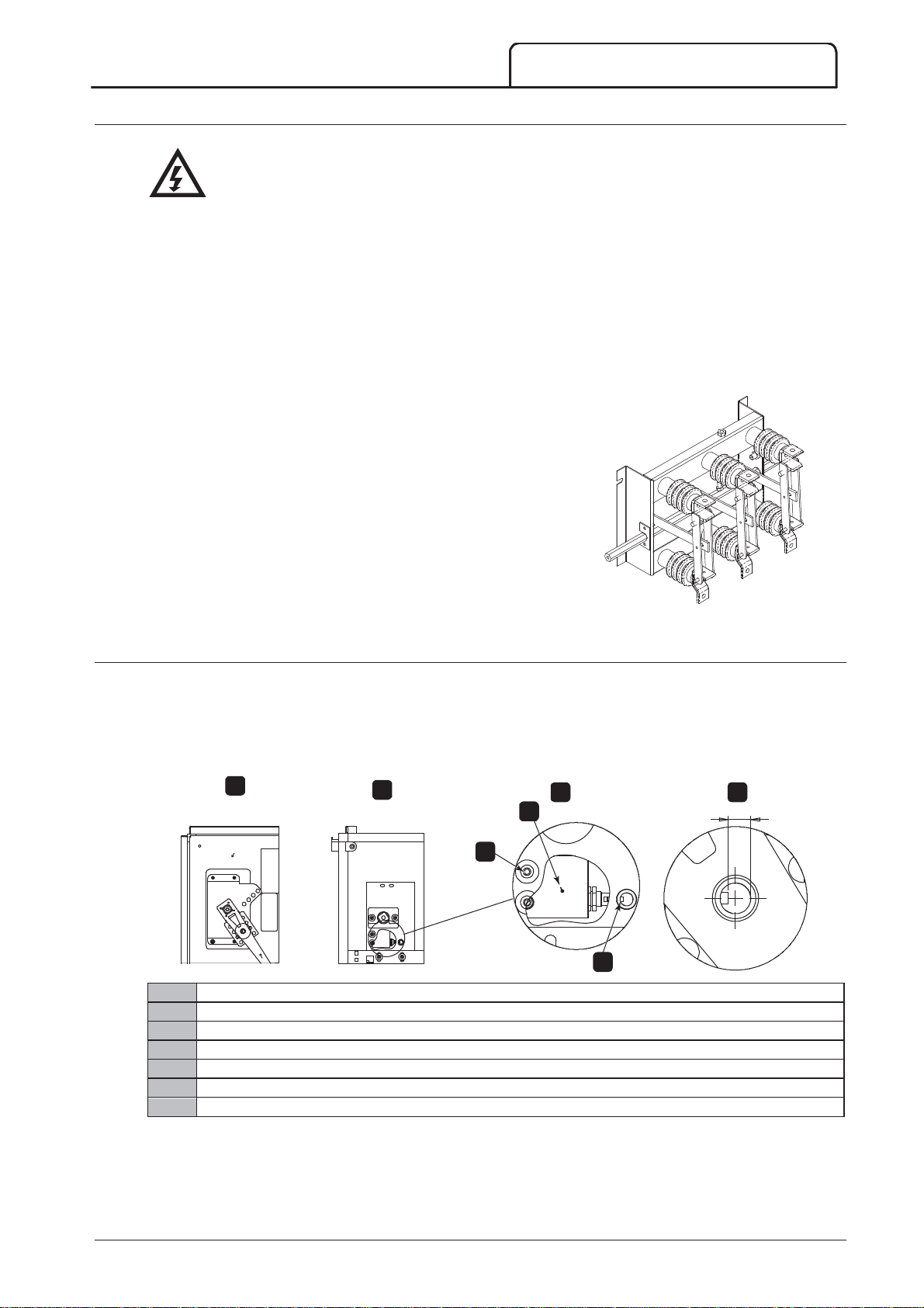
14.6 Isolation Switch Maintenance
WARNING
A
B
C
D
1
2
3
W
Do not operate the switch while current is flowing (motor or capacitor).
The isolation switch is designed for use in any MVS panel and it is not designed for outdoor use. The
isolation switch must be installed with a breaker or similar device on the supply side to limit the prospective
fault energy. Fuses must be used on the motor side of the switch.
1. Isolate the power supply before beginning any work on the
isolation switch.
2. Inspect the switch contacts for signs of wear. If there is
evidence of wear, contact your local supplier for replacement
parts.
3. Check that the microswitch activates when removing the
isolator locking pin.
4. With the switch in the closed position check the contact
resistance for each pole of the switch.
5. Use a lint-free cloth to clean the isolation switch. Warm
soapy water may be necessary in cleaning.
6. Wipe the main contacts and main arms with Electrolube
(Electrolube part # CG35A) at points of contact.
MAINTENANCE
14.7 Isolator Microswitch Adjustment
If the microswitch does not activate correctly, adjust the position of the plunger.
1. Remove the isolation switch handle and the MVS panel front cover.
2. Adjust the position of the microswitch bracket by turning the adjusting screws.
The plunger must be horizontally aligned with the centre of the locking pin tube.
The end of the plunger must be approximately 8 mm from the edge of the locking pin tube.
A
16776.A
Front cover and handle in place
Front cover and handle removed
Microswitch location
Microswitch detail
Bracket
Adjustment screws
Plunger
B
07449.B
Adjust to less than 60 (micro ohms)
C D
1
8 mm
2
3
710-13937-00C MVS Panel User Manual 79
Page 81

MAINTENANCE
WARNING
NOTE
14.8 Phase Arm Assembly Alignment (model V13)
The phase arm locates itself at the fully withdrawn state when sliding in and out of the frame.
During the commissioning process, during maintenance and when installing a phase arm check the phase arm
alignment.
W
Do not extend more than one phase arm at any one time.
Torque all bolts after alignment.
1. Loosen both rear busbar captive bolts and four
(4) domed socket head cap screws on the rear
of the phase arm. The busbar captive bolts are
loose at the point of resistance.
2. Loosen the phase block mounting bolts on both
sides of the phase assembly that hold it to the
tray.
3. Remove the phase arm locking nuts on both
sides.
4. Slide out the phase arm assembly.
5. Slide in the phase arm assembly to check
alignment.
6. Align the phase block on left or right as required.
7. Align and secure the main phase connection
captive bolts.
8. Tighten locking rod on both sides to 10 Nm.
9. Tighten nut and washer on both sides of the
phase arm to 10 Nm.
10. Secure dome head bolts (nip and secure) on the
bus work to 30 Nm.
11. Secure the cap head dome bolts on the phase
blocks. Torque to 12 Nm.
12. Re-adjust if required by repeating steps 3-10
above.
80 MVS Panel User Manual 710-13937-00C
Page 82
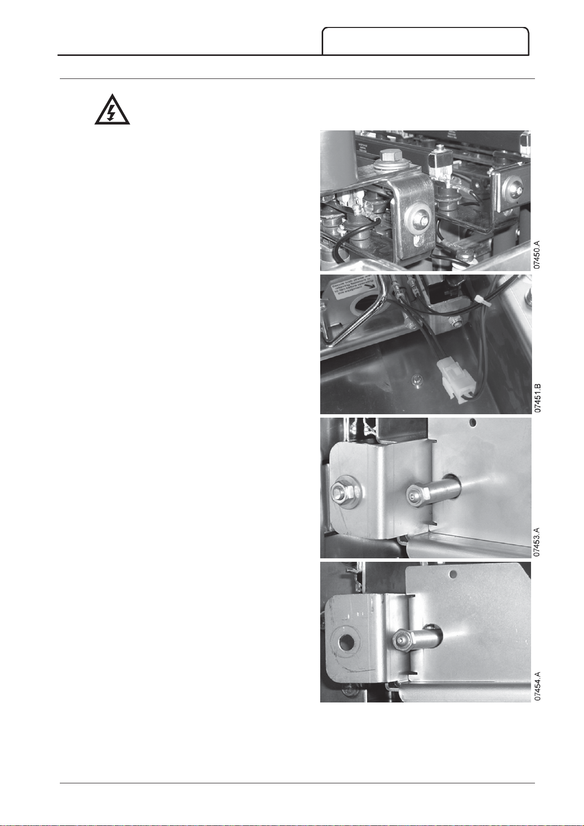
14.9 Removing Phase Arms (model V13)
WARNING
W
Do not extend more than one phase arm at any one time.
1. Undo the two phase connection bolts at the
rear of the phase arm.
2. Remove the nut and washer and undo the rod
bolt on both sides.
3. Unplug the controls on the right hand side.
MAINTENANCE
4. On both sides, remove the nut and washer and
undo the rod bolt.
5. Withdraw the phase arm.
710-13937-00C MVS Panel User Manual 81
Page 83
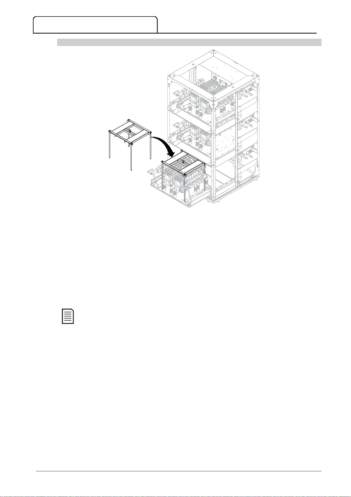
MAINTENANCE
NOTE
Removing Phase Arms with a Lifting Frame
07455.B
To remove a phase arm with a forklift:
1. Slide the phase arm out from the panel.
2. Place the lifting frame on the phase arm and tighten bolts.
3. Position the forks at 210 mm from fork to fork.
4. Taking care not to touch any other components, slowly slide the forks into the fork guide slot under the
lifting frame.
5. Raise forks slightly to allow frame to clear location holes.
6. Remove the phase arm.
To remove a phase arm using a hoist:
1. Slide the phase arm out from the panel.
2. Secure a cable from the hoist to the lifting eye
3. Lift the phase arm slowly, stabilising the phase arm to prevent it spinning.
Lifting Frame Assembly
(part no: 995-06391-00) is required for this.
82 MVS Panel User Manual 710-13937-00C
Page 84
1PPrimary Motor Settings
User Set 1
User Set 2
Default Value
2SStart/Stop Modes--11
3AAuto--SStart/Stop
4PProtection Settings
5AAuto--RReset Trips (
Reserved
)
6IInputs
15 Appendix
15.1 Parameter Defaults
If you require assistance from your supplier or a service technician, please note all parameter settings in the table
below.
APPENDIX
1
1A
1B
1C
1D
2
2A
2B
2C
2D
2E
2F
2G
2H
2I
3
3A
3B
3C
3D
4
4A
4B
4C
4D
4E
4F
4G
4H
4I
4J
4K
4L
4M
4N
4O
4P
4Q
4R
4S
4T
4U
4V
5
5A
6
6A
6B
6C
6D
6E
6F
Motor Full Load Current
Locked Rotor Time
Locked Rotor Current
Motor Service Factor
Start Mode
Start Ramp Time
Initial Current
Current Limit
Reserved
Kickstart Time
Kickstart Level
Stop Mode
Stop Time
Reserved
Reserved
Auto-Stop Type
Auto-Stop Time
Excess Start Time
Excess Start Time-2
Undercurrent
Undercurrent Delay
Instantaneous Overcurrent
Instantaneous Overcurrent Delay
Phase Sequence
Current Imbalance
Current Imbalance Delay
Frequency Check
Frequency Variation
Frequency Delay
Restart Delay
Motor Temperature Check
Ground Fault Level
Ground Fault Delay
Undervoltage
Undervoltage Delay
Overvoltage
Overvoltage Delay
Instantaneous Overcurrent S2
Instantaneous Overcurrent Delay S2
R
)
Reserved
Input A Function
Input A Name
Input A Trip
Input A Trip Delay
Input A Initial Delay
Input B Function
U
U
D
100 A
00m:10s
600% FLC
105%
Constant Current
00m:01s
400% FLC
400% FLC
0ms
500% FLC
Coast To Stop
00m:00s
Off
00h:01m
00m:20s
00m:20s
20% FLC
00m:05s
400% FLC
00m:00s
Positive Only
30%
00m:05s
Run
±5 Hz
00m:05s
30m:00s
Do Not Check
1A
00m:03s
100 V
00m:05s
7200 V
00m:05s
4400 A
10 ms
Input Trip (N/O)
Input Trip
Always Active
00m:00s
00m:00s
Input Trip (N/O)
710-13937-00C MVS Panel User Manual 83
Page 85
APPENDIX
7OOutputs
8DDisplay
9MMotor Data--22
10SStart/Stop Modes--22
6G
6H
6I
6J
6K
6L
6M
6N
6O
6P
6Q
6R
7
7A
7B
7C
7D
7E
7F
7G
7H
7I
7J
7K
7L
7M
7N
7O
7P
7Q
7R
7S
7T
7U
7V
7W
8
8A
8B
8C
8D
8E
8F
8G
8H
8I
8J
8K
8L
8M
9
9A
9B
9C
9D
9E
1
10A
10B
Input B Name
Input B Trip
Input B Trip Delay
Input B Initial Delay
Reserved
Reserved
Remote Reset Logic
Reserved
Reserved
Reserved
Local/Remote
Comms in Remote
Relay A Function
Relay A On Delay
Relay A Off Delay
Relay B Function
Relay B On Delay
Relay B Off Delay
Relay C Function
Relay C On Delay
Relay C Off Delay
Reserved
Reserved
Reserved
Low Current Flag
High Current Flag
Motor Temperature Flag
Analog Output A
Analog A Scale
Analog A Maximum Adjustment
Analog A Minimum Adjustment
Reserved
Reserved
Reserved
Reserved
Language
F1 Button Action
F2 Button Action
Display A or kW
User Screen - Top Left
User Screen - Top Right
User Screen - Bottom Left
User Screen - Bottom Right
Graph Data
Graph Timebase
Graph Maximum Adjustment
Graph Minimum Adjustment
Mains Reference Voltage
Reserved
Motor FLC-2
Reserved
Reserved
Reserved
Start Mode-2
Start Ramp-2
Input Trip
Always Active
00m:00s
00m:00s
Normally Closed (N/C)
LCL/RMT Anytime
Enable Control in RMT
Main Contactor
00m:00s
00m:00s
Run
00m:00s
00m:00s
Trip
00m:00s
00m:00s
50% FLC
100% FLC
80%
Current (% FLC)
4-20 mA
100%
0%
English
Setup Auto-Start/Stop
None
Current
Starter State
Blank
kWh
Hours Run
Current (% FLC)
10 seconds
400%
0%
400 V
100 A
Constant Current
00m:01s
84 MVS Panel User Manual 710-13937-00C
Page 86
APPENDIX
11RRTD/PT100 (
Reserved
)
12SSlip--RRing Motors
15AAdvanced
16PProtection Action
20RRestricted
10C
10D
10E
10F
10G
10H
10I
1
11A
1
12A
12B
12C
12D
1
15A
15B
15C
1
16A
16B
16C
16D
16E
16F
16G
16H
16I
16J
16K
16L
16M
16N
16O
16P
16Q
16R
16S
16T
16U
16V
16W
2
Initial Current-2
Current Limit-2
Reserved
Kickstart Time-2
Kickstart Level-2
Stop Mode-2
Stop Time-2
R
)
Reserved
Motor Data-1 Ramp
Motor Data-2 Ramp
Changeover Time
Slip Ring Retard
Access Code
Adjustment Lock
Emergency Run
Motor Overload
Excess Start Time
Undercurrent
Instantaneous Overcurrent
Current Imbalance
Frequency
Input A Trip
Input B Trip
Motor Thermistor
Starter Communication
Network Communication
Reserved
Battery/Clock
Ground Fault
Reserved
Reserved
Reserved
Reserved
Reserved
Reserved
Reserved
Undervoltage
Overvoltage
400% FLC
400% FLC
0ms
500% FLC
Coast To Stop
00m:00s
Single Ramp
Single Ramp
150 ms
50%
0000
Read & Write
Disable
Trip Starter
Trip Starter
Trip Starter
Trip Starter
Trip Starter
Trip Starter
Trip Starter
Trip Starter
Trip Starter
Trip Starter
Warn and Log
Warn and Log
Trip Starter
Trip Starter
Trip Starter
710-13937-00C MVS Panel User Manual 85
Page 87
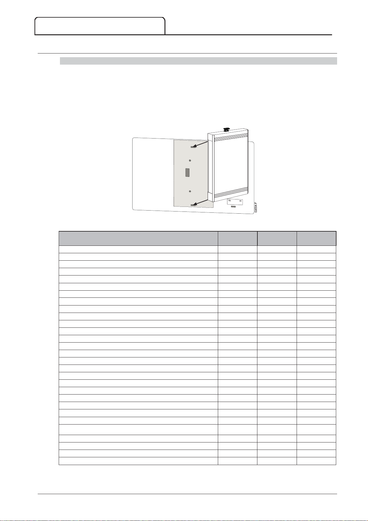
APPENDIX
Description
Profibus DP /
Profinet
Modbus RTU /
Modbus TCP
DeviceNet /
Ethernet/IP
15.2 Accessories
Communication Interfaces
MVS soft starters support network communication via easy-to-install communications interfaces. Each soft starter
can support one communications interface at a time.
Available protocols:
Ethernet (Profinet, Modbus TCP, Ethernet/IP), Profibus, DeviceNet, Modbus RTU, and USB.
Installing Communication Modules
Communication modules attach to the back of the controller:
Trip Codes (Serial Communication Network)
Excess start time 1 1 101
Motor overload 2 2 20
Motor thermistor 3 3 75
Current imbalance 4 4 26
Frequency 5 5 55
Phase sequence 6 6 54
Instantaneous overcurrent 7 7 28
Power loss 8 8 50
Undercurrent 9 9 29
Motor connection 11 11 102
Input A trip 12 12 11
Starter communication (between module and soft starter) 15 15 113
Network communication (between module and network) 16 16 114
Internal fault/error 17 17 104
Overvoltage 18 18 52
Undervoltage 19 19 51
Ground fault 20 20 27
EEPROM fail 23 23 62
Input B trip 24 24 110
Bypass fail (bypass contactor) 25 25 105
L1 phase loss 26 26 23
L2 phase loss 27 27 24
L3 phase loss 28 28 25
L1-T1 shorted 29 29 115
L2-T2 shorted 30 30 116
L3-T3 shorted 31 31 117
Battery/clock 35 35 121
Miscellaneous n/a n/a 70
No trip 255 255 0
86 MVS Panel User Manual 710-13937-00C
Page 88
APPENDIX
NOTE
PC Software
WinMaster is a purpose-designed software suite for control and monitoring a soft starter. WinMaster is compatible
with all AuCom soft starter ranges and is ideal for parameter management during commissioning. WinMaster has
the following features:
Operational control (Start, Stop, Reset, Quick Stop)
Starter status monitoring (Ready, Starting, Running, Stopping, Tripped)
Performance monitoring (motor current, motor temperature)
Upload parameter settings
Download parameter settings
To use WinMaster with the MVS, the soft starter must be fitted with a USB Module (PIM-USB-01) or a Modbus
Module (PIM-MB-01).
Refer to the WinMaster Help for further details.
Starter Trip and Event Logger Software
The Starter Trip and Event Logger Software allows you to download the trip and event logs from the soft starter,
for separate analysis.
The software is compatible with all AuCom medium voltage soft starters using control software version 1.29 or
later.
For further information, or to download the software, visit www.aucom.com.
Other MVS Accessories
Other accessories available to enhance your MVS starter include:
RTD protection relay
Motor protection relay (external to MVS)
Power meter
Indication lamps
Start, stop and reset pushbuttons
Local/remote selector switch
Internal panel light for low voltage section
Panel heater
Power supply and contactor for motor heater
Control transformers
Metering VT
MV/LV control supply transformer
Other accessories may be available on request.
710-13937-00C MVS Panel User Manual 87
Page 89

APPENDIX
88 MVS Panel User Manual 710-13937-00C
Page 90

 Loading...