

Page 1
GUIDE
MVS SERIES SOFT STARTERS
PRODUCT
Page 2

CONTENTS
MVS Series 1 710-03261-00D
Contents
Introduction ......................................................................................................................................3
Caution Statements ...................................................................................................3
General Description...................................................................................................4
2.1 Overview ................................................................................................4
2.2 About This Document ............................................................................4
2.3 Feature List ............................................................................................4
2.4 Part Number Format ..............................................................................5
Specifications.............................................................................................................6
3.1 Current Ratings......................................................................................6
3.2 Dimensions and Weights .......................................................................7
3.3 Key Components ...................................................................................8
3.4 General Technical Data .........................................................................8
Installation ......................................................................................................................................10
Key Features ...........................................................................................................10
Installation................................................................................................................11
4.1 Mounting Instructions - Power Assembly.............................................11
4.2 Mounting Instructions - MVS Controller...............................................12
4.3 Power Terminations .............................................................................13
4.4 Earth Terminations...............................................................................14
4.5 Control Terminations............................................................................14
4.6 Terminal Block (MVS Controller) .........................................................14
Power Circuits..........................................................................................................15
5.1 Overview ..............................................................................................15
5.2 Main Contactor.....................................................................................15
5.3 Bypass Contactor.................................................................................15
5.4 Main Isolator/ Earth Switch ..................................................................16
5.5 R Rated Protection Fuses....................................................................16
5.6 Power Factor Correction ......................................................................17
5.7 Line Inductors ......................................................................................17
5.8 Transient/ Overvoltage Protection .......................................................17
5.9 Control Supply Transformer.................................................................18
5.10 Enclosures ..........................................................................................19
Control Circuits ........................................................................................................20
6.1 Electrical Schematic.............................................................................20
6.2 Internal Wiring......................................................................................21
6.3 Control Wiring ......................................................................................22
Setup Tools..............................................................................................................23
7.1 Simulation Tools ..................................................................................23
7.2 Low Voltage Test Mode .......................................................................23
Operation ........................................................................................................................................25
Key Features ...........................................................................................................25
User Interface ..........................................................................................................26
8.1 MVS Controller.....................................................................................26
8.2 Menus ..................................................................................................26
8.3 Security ................................................................................................27
8.4 LEDs ....................................................................................................28
8.5 Commissioning Menu ..........................................................................28
Page 3

CONTENTS
710-03261-00D 2 MVS Series
8.6 Programming Menu .............................................................................34
8.7 Logs Menu ...........................................................................................36
Operation .................................................................................................................40
9.1 Using the MVS to Control a Motor .......................................................40
9.2 Using the MVS to Control a Slip-Ring Motor .......................................40
9.3 Motor, System and Soft Starter Protection Mechanisms.....................42
9.4 Motor Overload Protection ...................................................................42
Operating Feedback ................................................................................................43
10.1 Metering Screens ................................................................................43
10.2 Starter Status ......................................................................................43
10.3 Current ................................................................................................44
10.4 Voltage and Current............................................................................44
10.5 Power Metering ...................................................................................44
10.6 Last Start Information..........................................................................44
10.7 Date/Time............................................................................................44
10.8 Programmable Screen ........................................................................45
Appendix.........................................................................................................................................46
Menu Maps..............................................................................................................46
11.1 Programming Menu.............................................................................46
11.2 Commissioning Menu .........................................................................47
11.3 Logs Menu ..........................................................................................47
AuCom Enclosures..................................................................................................48
Accessories .............................................................................................................49
13.1 Communication Interfaces ..................................................................49
13.2 PC Software ........................................................................................50
Page 4
INTRODUCTION: CAUTION STATEMENTS
MVS Series 3 710-03261-00D
Introduction
Caution Statements
1
This symbol is used throughout this manual to draw attention to topics of
special importance to the installation and operation of MVS Series soft
starters.
Caution Statements cannot cover every potential cause of equipment damage but
can highlight common causes of damage. It is the installer's responsibility to
adhere to all instructions in this manual, to follow good electrical practice and to
seek advice before operating this equipment in a manner other than as described
in this manual.
• Ensure that the soft starter is completely isolated from the power supply before
attempting any work on the unit.
• Entry of metal swarf into the cabinet can cause equipment failure.
• Do not apply voltage to the control input terminals. These are active 24 VDC
inputs and must be controlled with potential free circuits.
• Ensure contacts or switches operating the control inputs are suitable for low
voltage, low current switching (ie gold flash or similar).
• Ensure cables to the control inputs are segregated from AC power and control
wiring.
• Some electronic contactor coils are not suitable for direct switching with PCB
mount relays. Consult the contactor manufacturer/ supplier to see if this is
advisable.
• Do not connect power factor correction capacitors to the output of MVS soft
starters. If static power factor correction is employed, it must be connected to
the supply side of the soft starter.
The examples and diagrams in this manual are included solely for illustrative
purposes. The information contained in this manual is subject to change at any
time and without prior notice. In no event will responsibility or liability be accepted
for direct, indirect or consequential damages resulting from the use or application
of this equipment.
WARNING - ELECTRICAL SHOCK HAZARD
MVS soft starters contain dangerous voltages when connected to line
voltage. Only a competent electrician should carry out the electrical
installation. Improper installation of the motor or the soft starter may cause
equipment failure, serious injury or death. Follow this manual, the National
Electrical Code (NEC
®
) and local safety codes.
SHORT CIRCUIT
MVS soft starters are not short circuit proof. After severe overload or short
circuit, the operation of the soft starter should be fully tested.
GROUNDING AND BRANCH CIRCUIT PROTECTION
It is the responsibility of the user or person installing the soft starter to
provide proper grounding and branch circuit protection according to the
National Electrical Code (NEC
®
) and local safety codes.
Section 1
Chapter 1
Page 5

INTRODUCTION: GENERAL DESCRIPTION
710-03261-00D 4 MVS Series
General Description
2
2.1 Overview
The MVS Series provides compact and robust soft start solutions for control of
medium voltage motors. MVS soft starters provide a complete range of motor and
system protection features and have been designed for reliable performance in the
most demanding installation situations.
Each MVS soft starter comprises two elements:
• a power assembly
• a controller module
The power assembly and controller module are supplied as a pair and share the
same serial number. Care should be taken during installation to ensure the correct
controller and power assembly are used together.
Each MVS is also supplied with two fibre-optic cables, to connect the controller
module to the power assembly, and three non-conduction resistor assemblies,
allowing the soft starter to be tested with a low-voltage motor (< 500 VAC).
2.2 About This Document
This document describes the features of MVS soft starters. This document has
been designed to give engineers a general overview of the functionality of the
MVS.
2.3 Feature List
Starting
• Constant current
• Current ramp
Stopping
• Coast to stop
• Soft stop
Protection
• Under/ Overvoltage
• Mains frequency
• Phase sequence
• Shorted SCR
• Motor overload (thermal model)
• Instantaneous overcurrent
• Ground fault
• Undercurrent
• Current Imbalance
• Motor thermistor
• Excess start time
• Power circuit
• Auxiliary trip
Interface
• Remote control inputs
(3 x fixed, 2 x programmable)
• Relay outputs
(3 x fixed, 3 x programmable)
• Analog output
(1 x programmable)
• Serial port
Human Interface
• Multi-language display
• Starter status LEDs
• Event log (99 positions, date and time
stamped)
• Trip log (8 positions, date and time
stamped)
• Counters (starts, hours-run, kWh)
• Metering (current, voltage, power
factor, kWh)
• User-programmable metering screen
• Multi-level password protection
Power Connection
• 80 A to 321 A, nominal
• 2300 VAC to 11000 VAC
Accessories (optional)
• Modbus RTU Interface
• Profibus Interface
• DeviceNet Interface
• Synchronous motor control
• PC Software
• Overvoltage protection
• Control supply transformer
Chapter 2
Page 6
INTRODUCTION: GENERAL DESCRIPTION
MVS Series 5 710-03261-00D
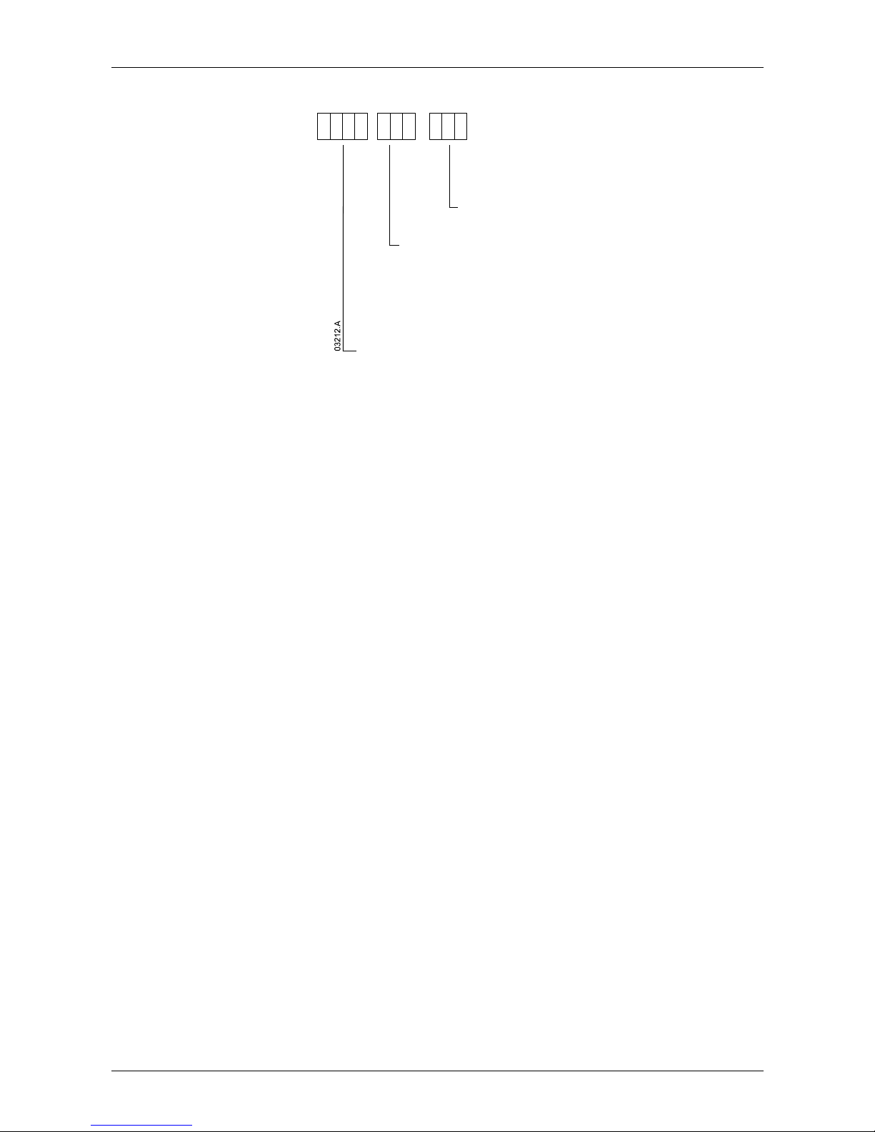
2.4 Part Number Format
Supply Voltage
V02 = 2300 VAC 50 / 60 Hz
V03 = 3300 VAC 50 / 60 Hz
V04 = 4160 VAC 50 / 60 Hz
V06 = 6600 VAC 50 / 60 Hz
V07 = 7200 VAC 50 / 60 Hz
V11 = 11000 VAC 50 / 60 Hz
Control Supply Voltage
C12 = 110 VAC & 230 VAC
MVS
--
Current Rating
0080 = 80 A @ AC53b 4-20 : 1780
0159 = 159 A @ AC53b 4-20 : 1780
0230 = 230 A @ AC53b 4-20 : 1780
0321 = 321 A @ AC53b 4-20 : 1780
Page 7
INTRODUCTION: SPECIFICATIONS
710-03261-00D 6 MVS Series
Specifications
3
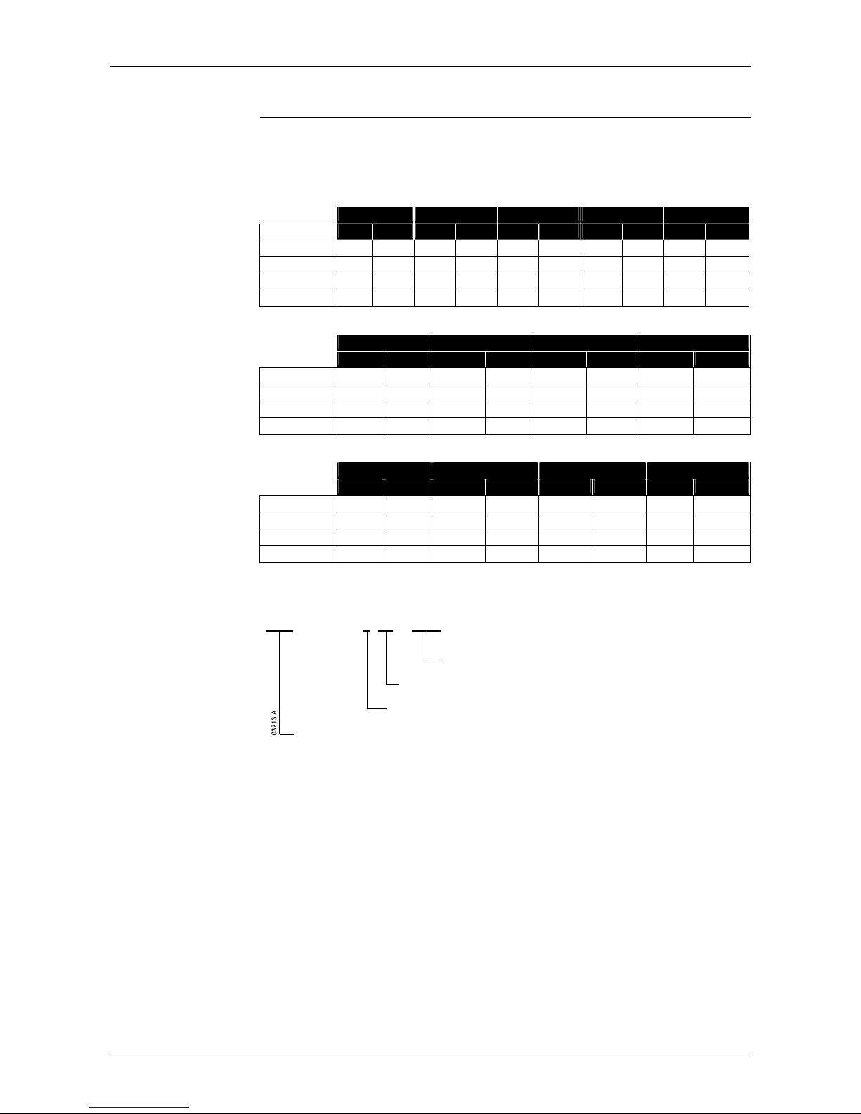
3.1 Current Ratings
(At 1000 m.)
Two starts per hour
3.5-15 : 1785 4.0-20 : 1780 4.0-30 : 1770 5.0-30 : 1770 5.0-60 : 1740
40 °C 50 °C 40 °C 50 °C 40 °C 50 °C 40 °C 50 °C 40 °C 50 °C
MVS0080
96 91 80 74 72 66 59 55 46 42
MVS0159
190 177 159 147 143 132 117 109 91 84
MVS0230
282 261 230 213 201 185 165 152 121 111
MVS0321
393 363 321 296 279 257 229 211 168 154
Three starts per hour
4.0-20 : 1180 4.0-30 : 1170 5.0-30 : 1170 5.0-60 : 1140
40 °C 50 °C 40 °C 50 °C 40 °C 50 °C 40 °C 50 °C
MVS0080
73 68 65 60 53 49 40 37
MVS0159
146 135 129 119 106 98 79 73
MVS0230
207 190 175 162 144 132 101 93
MVS0321
288 265 244 225 200 184 141 129
Four starts per hour
4.0-20 : 880 4.0-30 : 870 5.0-30 : 870 5.0-60 : 840
40 °C 50 °C 40 °C 50 °C 40 °C 50 °C 40 °C 50 °C
MVS0080
68 63 59 54 48 45 35 33
MVS0159
136 125 117 108 96 89 70 65
MVS0230
188 173 157 144 129 118 88 81
MVS0321
262 241 218 200 179 164 122 112
AC53b Utilisation Category Format
80 A: AC-53b 4-20 : 1780
Off Time
(seconds)
Sta rt Ti me
(seconds)
Start Current (multiple of FLC)
Starter Current Rating (am peres)
Starter Current Rating: The full load current rating of the soft starter given the
parameters detailed in the remaining sections of the utilisation code.
Start Current: The maximum available start current given the parameters detailed
in the remaining sections of the utilisation code.
Start Time: The maximum available start time given the parameters detailed in the
remaining sections of the utilisation code.
Off Time: The minimum allowable time between the end of one start and the
beginning of the next start given the parameters detailed in the remaining sections
of the utilisation code.
Contact your local supplier for ratings under operating conditions not covered by
the above ratings charts.
Chapter 3
Page 8
INTRODUCTION: SPECIFICATIONS
MVS Series 7 710-03261-00D
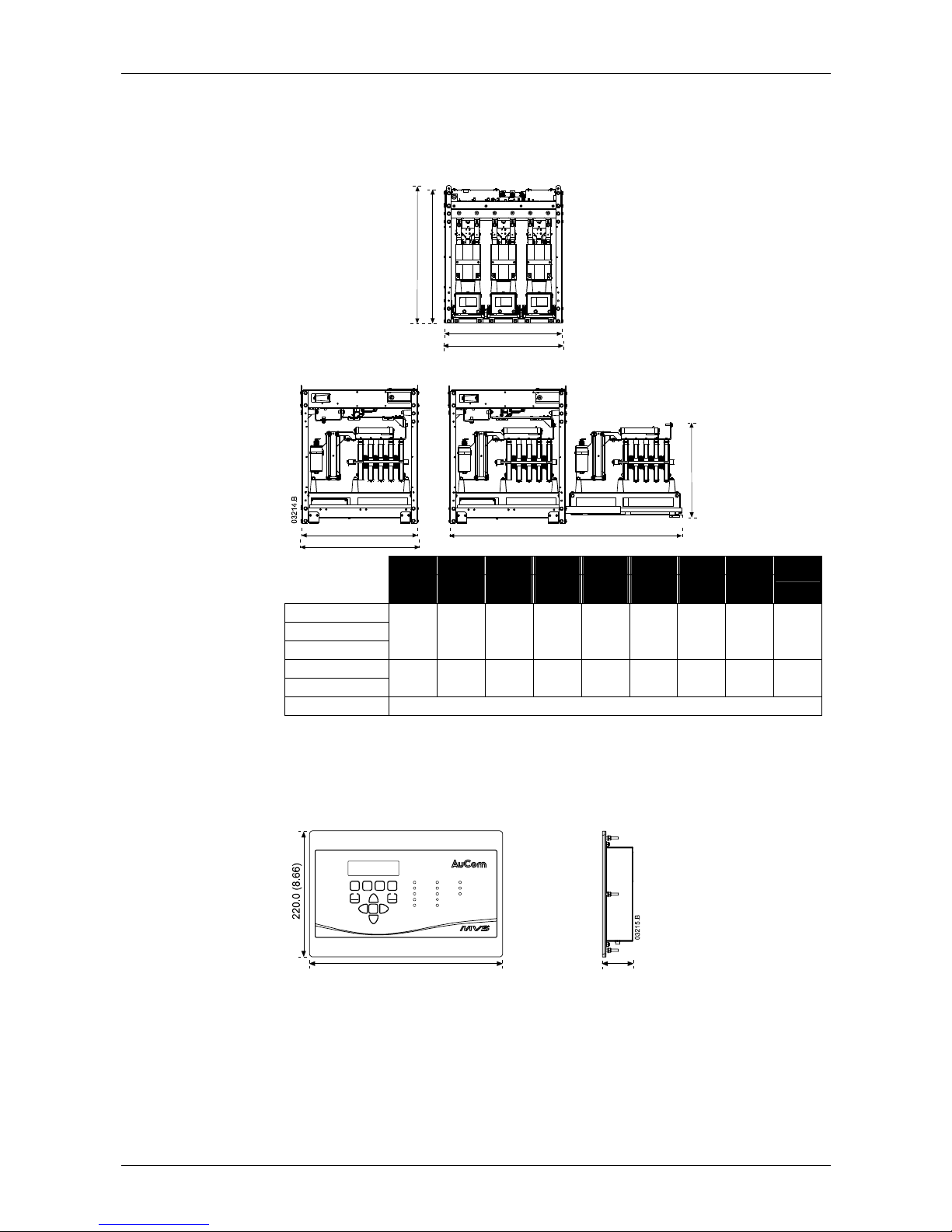
3.2 Dimensions and Weights
Power Assembly
A
a
b
B
c
C
d
e
Front View
Side View
Extended
A B C a b c d e
Weight
mm
(inch)
mm
(inch)
mm
(inch)
mm
(inch)
mm
(inch)
mm
(inch)
mm
(inch)
mm
(inch)
kg (lb)
MVSxxxx-V02
MVSxxxx-V03
MVSxxxx-V04
772
(30.4)
669
(26.3)
667
(26.3)
750
(29.5)
658
(25.9)
650
(25.6)
1302
(51.3)
531
(20.9)
165
(363.8)
MVSxxxx-V06
MVSxxxx-V07
832
(32.8)
875
(34.5)
817
(32.2)
810
(31.9)
864
(34.0)
800
(31.5)
1559
(61.4)
551
(21.7)
217
(478.4)
MVSxxxx-V11 Contact your local supplier for details.
Controller
The MVS Controller is suitable for use with all MVS soft starters.
340.0
(13.39)
54.0
(2.13)
Start
Stop
Reset
Input A
Input B
Start
Run
Trip
Warnin g
Remote
RLA
RLB
RLC
Series
START
LCL/
RMT
F1
LOGS
UNDO
STOP RESET
F2
SETUP
TOOLS
STORE
Fn
Start er
Status
Control
Inputs
Relay
Outputs
mm (inch)
Weight: 2.1 kg (4.63 lb)
Page 9
INTRODUCTION: SPECIFICATIONS
710-03261-00D 8 MVS Series
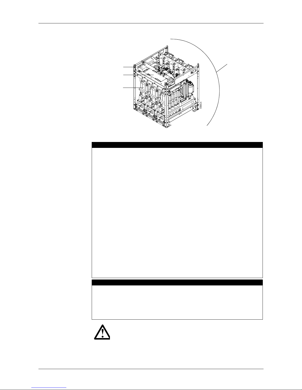
3.3 Key Components
Power assembly
Phase arms (x 3)
Power interface PCB
Control voltage
terminal block
3.4 General Technical Data
Supply
Mains Voltage
MVSxxxx-V02-xxx ...................................................... 3 x 2300 VAC (± 10%)
MVSxxxx-V03-xxx ...................................................... 3 x 3300 VAC (± 10%)
MVSxxxx-V04-xxx ...................................................... 3 x 4160 VAC (± 10%)
MVSxxxx-V06-xxx ...................................................... 3 x 6600 VAC (± 10%)
MVSxxxx-V07-xxx ...................................................... 3 x 7200 VAC (± 10%)
MVSxxxx-V11-xxx .................................................... 3 x 11000 VAC (± 10%)
Control Voltage
MVSxxxx-xxx-C12 .............................. 110 VAC to 130 VAC (+ 10% / - 15%)
or 220 VAC to 240 VAC (+ 10% / - 15%)
All models ..................................................................... 500 VA, single phase
Mains Frequency ........................................................................... 45 Hz to 66 Hz
Rated Insulation Voltage
MVSxxxx-V02-xxx ........................................................................ 11450 VAC
MVSxxxx-V03-xxx ........................................................................ 11450 VAC
MVSxxxx-V04-xxx ........................................................................ 11450 VAC
MVSxxxx-V06-xxx ........................................................................ 16800 VAC
MVSxxxx-V07-xxx ........................................................................ 18200 VAC
MVSxxxx-V11-xxx ................................................................................... TBA
Rated Impulse Withstand Voltage (BIL) - Overvoltage Category III
MVSxxxx-V02-xxx ~ MVSxxxx-V07-xxx ................................................ 45 kV
MVSxxxx-V11-xxx ................................................................................... TBA
Form Designation ......................... Bypassed semiconductor motor starter form 1
Control Inputs
Start (Terminals C23, C24) ................................................ 24 VDC, 8 mA approx
Stop (Terminals C31, C32) ................................................ 24 VDC, 8 mA approx
Reset (Terminals C41, C42) .............................................. 24 VDC, 8 mA approx
Input A (Terminals C53, C54) ............................................ 24 VDC, 8 mA approx
Input B (Terminals C63, C64) ............................................ 24 VDC, 8 mA approx
Motor Thermistor (Terminals B4, B5)
NOTE
All control inputs are potential free. Do not apply external voltage to
these inputs.
Page 10

INTRODUCTION: SPECIFICATIONS
MVS Series 9 710-03261-00D
Outputs
Relay Outputs .............................................................. 10 A @ 250 VAC/ 360 VA
10 A @ 30 VDC resistive
Main Contactor (Terminals 13, 14) ............................................... Normally Open
Bypass Contactor (Terminals 23, 24) ........................................... Normally Open
Run Output/ PFC (Terminals 33, 34) ............................................ Normally Open
Output Relay A (Terminals 43, 44) ............................................... Normally Open
Output Relay B (Terminals 51, 52, 54) ............................................ Changeover
Output Relay C (Terminals 61, 62, 64) ............................................. Changeover
Analog Output (Terminals B10, B11) ................................... 0-20 mA or 4-20 mA
Environmental
Degree of Protection
Power Assembly ...................................................................................... IP00
Controller ............................................................................... IP54/ NEMA 12
Operating Temperature ............................................................. - 10 ˚C to + 60 ˚C
Storage Temperature ................................................................ - 25 ˚C to + 55 ˚C
- 25 ˚C to + 70 ˚C (< 24 hours)
Humidity ................................................................ 5% to 95% Relative Humidity
Pollution Degree ...................................................................... Pollution Degree 3
Vibration ............................................ Designed to IEC 60068 Test Fc Sinusoidal
4 Hz to 13.2 Hz: ± 1 mm displacement
13.2 Hz to 200 Hz: ± 0.7 g
EMC Emission
Equipment Class (EMC) ............................................................................ Class A
Conducted Radio Frequency Emission ...... 10 kHz to 150 kHz: < 120 - 69 dB µV
0.15 MHz to 0.5 MHz: < 79 dB µV
0.5 MHz to 30 MHz: < 73 dB µV
Radiated Radio Frequency Emission ...... 0.15 MHz to 30 MHz: < 80-50 dB µV/m
30 MHz to 100 MHz: < 60-54 dB µV/m
100 MHz to 2000 MHz: < 54 dB µV/m
This product has been designed for Class A equipment. Use of the product in
domestic environments may cause radio interference, in which case the user may
be required to employ additional mitigation methods.
EMC Immunity
Electrostatic Discharge ..................... 6 kV contact discharge, 8 kV air discharge
Radio Frequency Electromagnetic Field ................ 80 MHz to 1000 MHz: 10 V/m
Fast Transients 5/50 ns (main and control circuits) .................................................
2 kV line to earth, 1 kV line to line
Surges 1.2/50 µs (main and control circuits) .. 2 kV line to earth, 1 kV line to line
Voltage dip and short time interruption ............ 5000 ms (at 0% nominal voltage)
(safe shutdown)
Short Circuit
Rated short-circuit current, symmetrical, fused (Class E2)
MVSxxxx-V02-xxx ~ MVSxxxx-V07-xxx ................................................ 48 kA
MVSxxxx-V11-xxx ................................................................................... TBA
Heat Dissipation (Steady State)
Power Assembly (SCRs bypassed) ................................................. 20 W approx
Controller ........................................................................................... 10 W approx
Standards Approvals
C9 ........................................................................................ EMC requirements
UL/ C-UL ...................................................................................... UL 508, UL 347
CE ......................................................................................... EMC EU Directive
Marine ...................................................................................................... pending
Page 11

INSTALLATION: KEY FEATURES
710-03261-00D 10 MVS Series
Installation
Key Features
The MVS offers several special functions to ensure safe and simple installation and
configuration.
Comprehensive Simulations
The MVS offers software-based simulation functions to check all aspects of
operation, including starting and stopping, protection mechanisms and signal inputs
and outputs. The simulations are accessed via the Commissioning Menu.
Low Voltage Test Mode
The low voltage test mode lets commissioning staff check the soft starter's
electrical configuration safely, without requiring access to specialised medium
voltage equipment. The MVS can start and stop a small three-phase motor, testing
associated equipment such as contactors and relays.
Section 2
Page 12
INSTALLATION: INSTALLATION
MVS Series 11 710-03261-00D
Installation
4
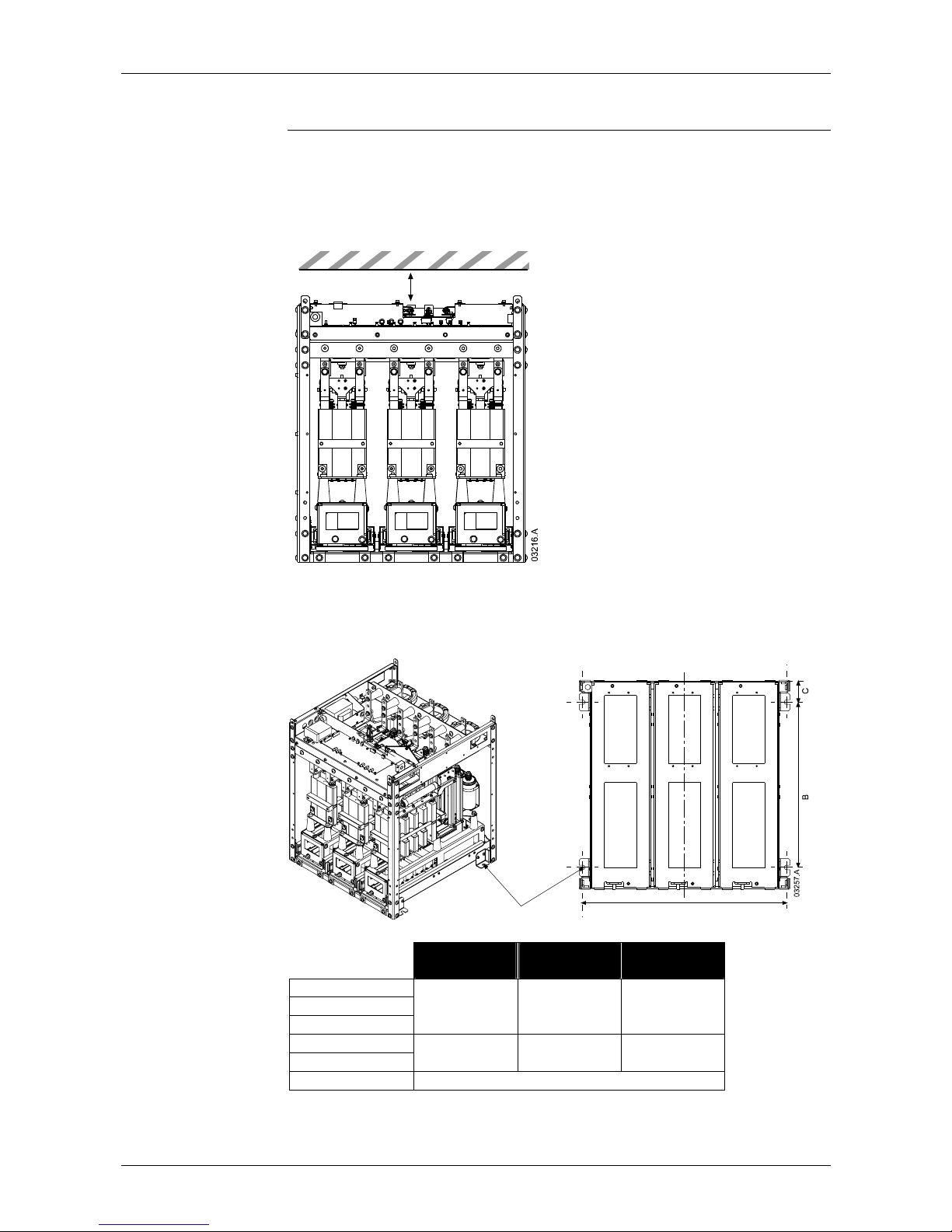
4.1 Mounting Instructions - Power Assembly
All MVS models have an IP00 rating and must be installed inside an enclosure.
The power assembly should be installed with 100 mm clearance above for
isolation. No clearance is required below or at the sides.
min 100 mm (3.93 inch)
The power assembly is mounted in place using four M12 bolts. One bolt is
required through each corner at the base of the unit, tightened to a torque of
40 Nm. Individual phase arms are secured within the frame using three M10 bolts,
tightened to a torque of 17 Nm.
Front of Unit
A
To suit M12 mounting bolt
Horizontal Cross-section
A
mm (inch) B mm (inch) C mm (inch)
MVSxxxx-V02
MVSxxxx-V03
MVSxxxx-V04
636
(25.04)
513
(20.20)
68.5
(2.70)
MVSxxxx-V06
MVSxxxx-V07
842
(33.15)
663
(26.10)
68.5
(2.70)
MVSxxxx-V11 Contact your local supplier.
Chapter 4
Page 13
INSTALLATION: INSTALLATION
710-03261-00D 12 MVS Series
4.2 Mounting Instructions - MVS Controller
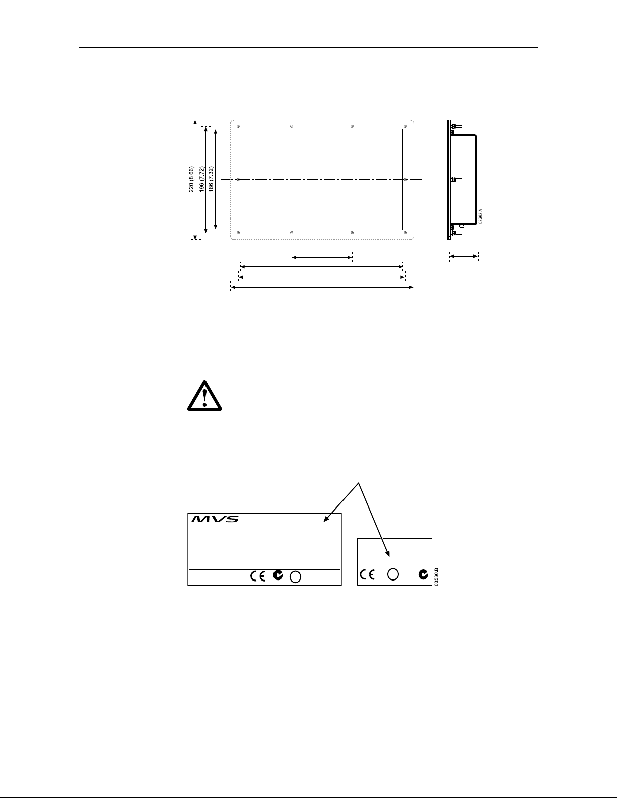
The MVS Controller can be secured in place with ten M4 nuts, affixed to the studs
on the back of the controller.
112 (4.41)
300 (11.81)
310 (12.20)
340 (13.39)
54.0 (2.13)
To mount the controller, make a 186 mm x 300 mm cutout at the desired mounting
location. Ensure adequate clearance (54 mm) is available behind the mounting
location.
Drill 5 mm holes to accommodate the studs on the controller. Fit the controller
through the cutout and tighten the nuts onto the studs.
NOTE
Before installation, always ensure that you are using the correct
controller for the soft starter. This can be checked by comparing
the serial number on the back of the controller with the serial
number on the front of the power assembly.
Serial number
MAIN CONTROL MODULE
MVS-0321-V04-C12
S/N: 989898-0
IND. CONT. EQ. 32AN Z79
C US
U
L
®
Serial Number
MVS 0321-V04-C1 2
O/C: MVS 0321 -411 S/N: 989898-0
INPUT RATING: 4160 VAC 50/60 Hz
OUTPUT RATING: 321 A : AC53b 4-20 1780
AUXILIARY CONTACTS: 10A, 30 VDC resistive / 10 A, 250 VAC 360 VA
WITHSTAND CURRENT: 48 kA
WITHSTAND VOLTAGE: 45000 VAC Cat III
AUXILIARY CONTACTS: #24-#14 AWG, 0.2-2.5 mm2 (0.5 NM, 4.4 lb-in)
AUCOM
IND. CONT. EQ.
32 AN
Series
Z79
C US
U
L
®
Page 14
INSTALLATION: INSTALLATION
MVS Series 13 710-03261-00D
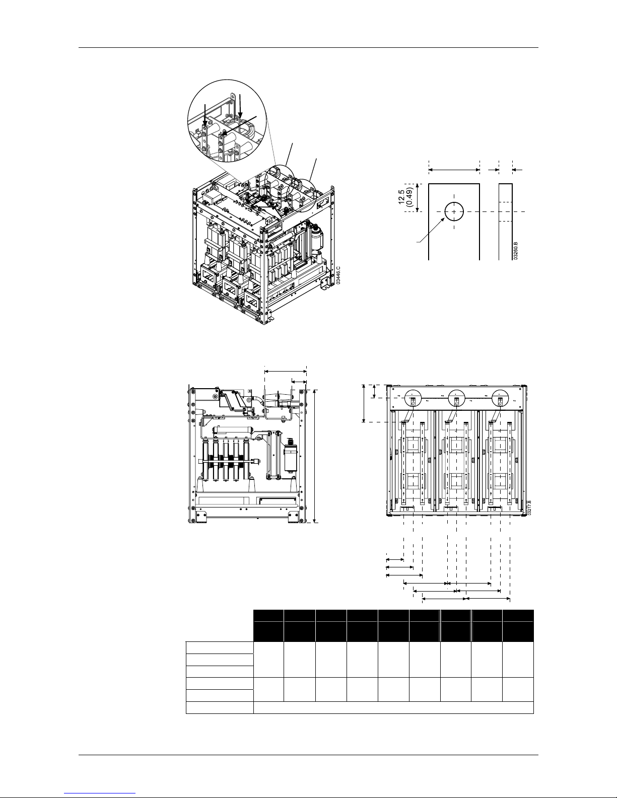
4.3 Power Terminations
T3B, T3, L3
T2B, T2, L2
L1
T1B
T1
6
(0.24)
25
(0.98)
13
(0.51)
The correct tightening torque depends on the termination being used - refer to the
manufacturer's specifications for details.
Rear of Unit
i
i
a
b
d
e
f
g
h
g
h
T1
T2
T3
L3L2L1 T3BT2BT1B
a
b
c
a b c d e f g h i
mm
(inch)
mm
(inch)
mm
(inch)
mm
(inch)
mm
(inch)
mm
(inch)
mm
(inch)
mm
(inch)
mm
(inch)
MVSxxxx-V02
MVSxxxx-V03
MVSxxxx-V04
228
(8.98)
79
(3.11)
744
(29.29)
79
(3.11)
129
(5.08)
179
(7.05)
200
(7.87)
200
(7.87)
200
(7.87)
MVSxxxx-V06
MVSxxxx-V07
228
(8.98)
79
(3.11)
804
(31.65)
107
(4.19)
164
(6.46)
222
(8.72)
268
(10.55)
268
(10.55)
268
(10.55)
MVSxxxx-V11 Contact your local supplier for measurements for MVSxxxx-V11.
Page 15
INSTALLATION: INSTALLATION
710-03261-00D 14 MVS Series
4.4 Earth Terminations
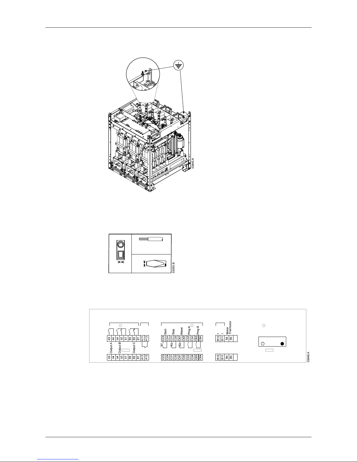
An earth stud is located on each side of the power assembly, at the rear of the unit.
4.5 Control Terminations
On the control voltage terminal block, control wiring is secured in place by 3 mm
spring terminals. Use a screwdriver to open the terminal clamp, then insert the wire
into the terminal cage. Release the clamp by removing the screwdriver.
Cable: 2.5 mm2 max
3 mm
3
mm
4.6 Terminal Block (MVS Controller)
Terminations on the MVS Controller use plug-in terminals. Unplug the terminal
blocks, complete the wiring, then re-plug the terminal blocks into the controller.
24 VAC
Relay Out puts
Control
Supply
Control Inputs
Fibre Optic Connection
To Power Assembly
Analog
Output
RX TX
Page 16

INSTALLATION: POWER CIRCUITS
MVS Series 15 710-03261-00D
Power Circuits
5
5.1 Overview
MVS soft starters are designed to operate as part of a system including other
components. A main contactor and bypass contactor are required in all
installations. The following additional components may also be required:
• main isolator/ earth switch
• R Rated protection fuses
• power factor correction
• line inductors
• transient/ overvoltage protection
• control supply transformer
5.2 Main Contactor
The MVS must always be installed with a main contactor. Select a contactor with
an AC3 rating greater than or equal to the full load current rating of the connected
motor.
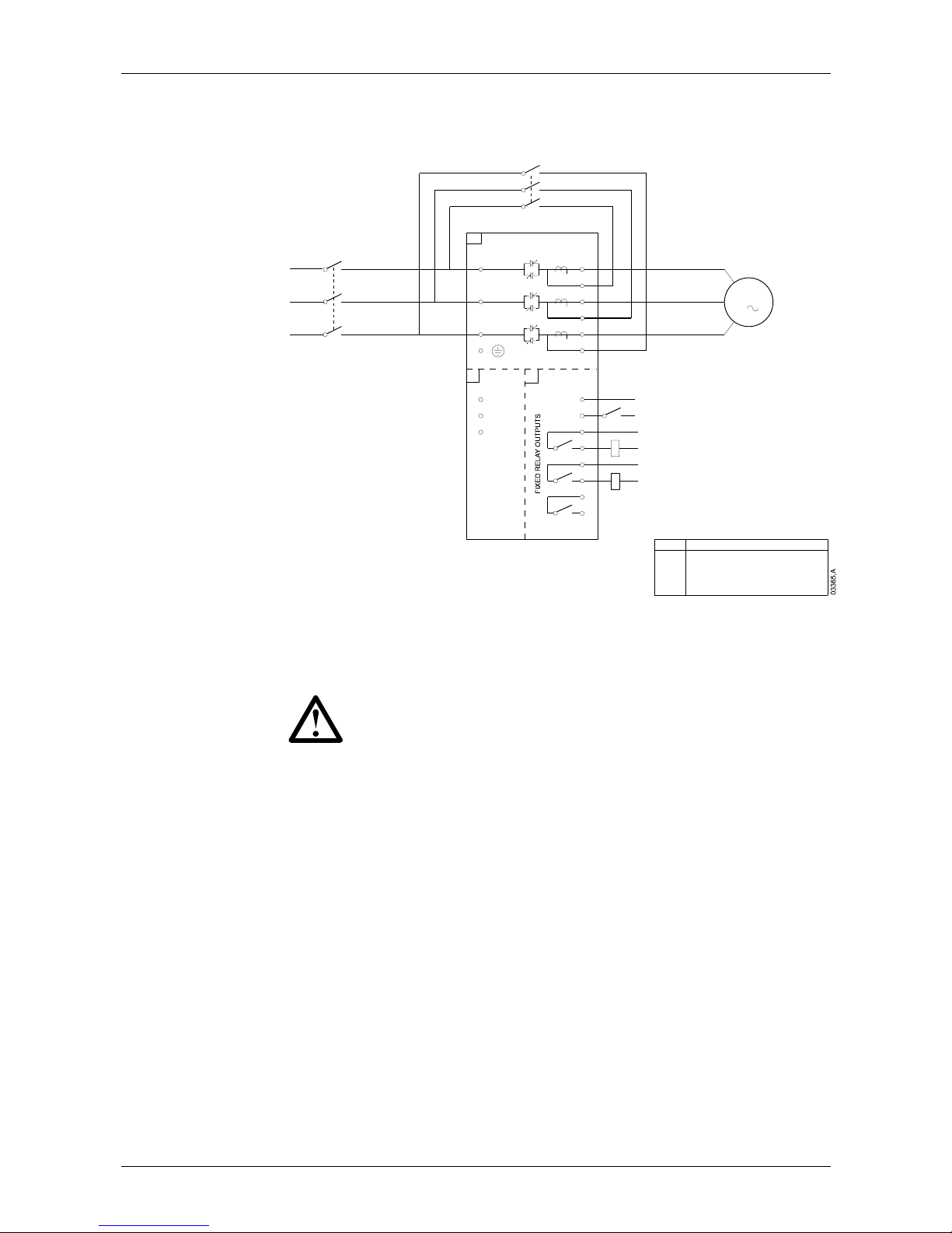
The main contactor is associated with terminals L1, L2, L3 on the supply side of the
soft starter. The coil is associated with output terminals 13, 14 of the MVS (refer to
Diagram 1: Standard Power Circuit Configuration on page 16).
To ensure that the potentially dangerous medium voltage area is isolated from the
low voltage control area, power is supplied to the main contactor coil from the
control voltage terminal block (refer to
Diagram 4: Internal Wiring on page 21).
5.3 Bypass Contactor
The MVS must always be installed with a bypass contactor. Select a contactor
with an AC1 rating greater than or equal to the full load current rating of the
connected motor.
The bypass contactor is associated with terminals L1, L2, L3 on the supply side of
the soft starter, and bypass terminals T1B, T2B, T3B on the motor side. The coil is
associated with output terminals 23, 24, and the auxiliary Normally Open contact is
associated with input terminals C73, C74 of the soft starter (refer to
Diagram 1:
Standard Power Circuit Configuration
on page 16).
To ensure that the potentially dangerous medium voltage area is isolated from the
low voltage control area, power is supplied to the bypass contactor coil from the
control voltage terminal block (refer to
Diagram 4: Internal Wiring on page 21).
Chapter 5
Page 17
INSTALLATION: POWER CIRCUITS
710-03261-00D 16 MVS Series
Diagram 1: Standard Power Circuit Configuration
MVS power circuit including main and bypass contactors.
T3B
BYPASS CONTACTOR
MAIN CONTACTOR
POWER INTERFACE PCB
CONTROL VOLTAGE TERMINAL BLOCK
POWER ASSEMBLY
DESCRIPTION
K2M
K1M
A3
A2
A1
ITEM
A3
A2
A1
K2M
T1B
T2B
E
L1
L2
L3
T1
T2
T3
A1
A2
A3
CONTROL
SUPPLY
13
14
23
24
C73
C74
BYPASS CONTACTOR
FEEDBACK SIGNAL
(PFC)
RUN OUTPUT
34
33
K2M
K1M
K2M BYPASS CONTACTOR
K1M MAIN CONTACTOR
3
M
MOTOR
5.4 Main Isolator/ Earth Switch
A main isolator/ earth switch can be connected on the supply side of the main
contactor (refer to
Diagram 2: Complete Power Circuit Configuration on page 18).
CAUTION
The main isolator/ earth switch should only be operated when the motor
is not running.
5.5 R Rated Protection Fuses
If specified, R Rated protection fuses can be installed on the supply side of the soft
starter to provide Type 2 coordination and short circuit protection for the motor
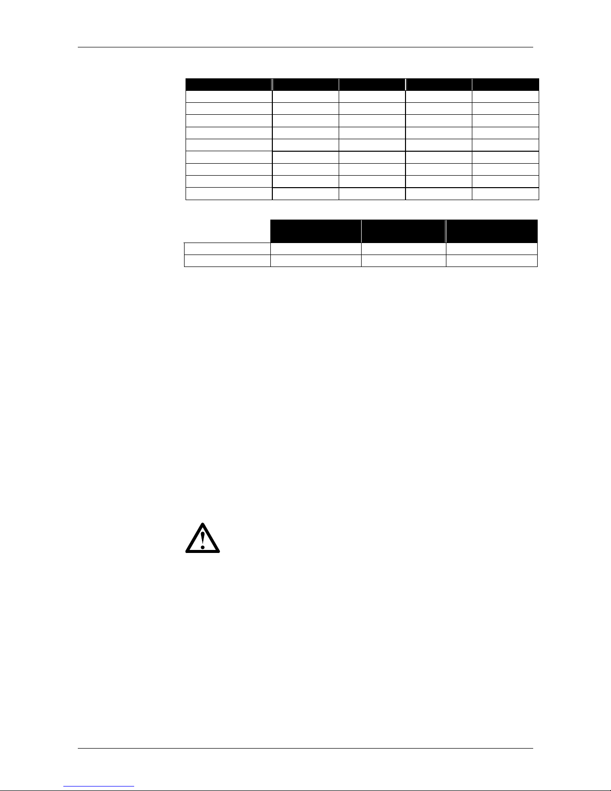
branch circuit. The appropriate fuse should be selected from the table below,
based on the motor's rated full load current.
This recommendation is based on two starts per hour (equally spaced) and
maximum ambient operating temperature of 40 ºC. Consult your local supplier for
operating conditions not covered by these charts.
Page 18
INSTALLATION: POWER CIRCUITS
MVS Series 17 710-03261-00D
Fuse ratings:
Motor Rated FLC 4.0-20:1780 4.0-30:1770 5.0-30:1770 5.0-60:1740
70 A 4R 4R 4R 5R
100 A 5R 5R 6R 9R
130 A 6R 6R 9R 9R
150 A 9R 9R 9R 12R
170 A 9R 9R 12R 12R
200 A 12R 12R 12R 18R
230 A 12R 12R 18R 18R
300 A 18R 18R 18R 24R
390 A 18R 18R 24R 24R
Fuse type code formats:
System Voltage
2.3 kV
System Voltage
3.3 ~ 4.2 kV
System Voltage
6 ~ 7.2 kV
Ferraz A240Rrr A480Rrr-1 A072xxDxRO-rr
Bussmann JCK-x-rr JCL-x-rr JCR-x-rr
rr = R rating of the fuse
x = physical format of the fuse (select according to installation requirements)
Examples:
6R fuse for 2.3 kV: A240R6R or JCK-A-6R
12R fuse for 3.3 kV: A480R12R-1 or JCL-B-12R
18R fuse for 6.6 kV: A072B1DARO-18R or JCR-B-18R
5.6 Power Factor Correction
Power factor correction capacitors should be selected based on the motor data and
the required final power factor.
If power factor correction capacitors are being used, select a contactor according to
the required kVAr. The contactor must be connected on the supply side of the soft
starter. The power factor correction capacitor contactor coil is associated with
output terminals 33, 34 of the soft starter's power interface PCB.
To ensure that the potentially dangerous medium voltage area is isolated from the
low voltage control area, power is supplied to the power factor correction capacitor
contactor coil from the control voltage terminal block (refer to
Diagram 4: Internal
Wiring
on page 21).
NOTE
The capacitor bank must be fed from the supply side of the soft starter.
5.7 Line Inductors
Line inductors are required if the cable run between the soft starter and the motor
is greater than 200 m. Line inductors should be installed outside the panel,
between the soft starter output (terminals T1, T2, T3) and the motor. Contact your
local supplier for selection details.
5.8 Transient/ Overvoltage Protection
Overvoltage protection should be installed if there is a risk of high transients at the
installation. If required, use the optional Overvoltage Protection Kit. Contact your
local supplier for details.
Page 19
INSTALLATION: POWER CIRCUITS
710-03261-00D 18 MVS Series
5.9 Control Supply Transformer
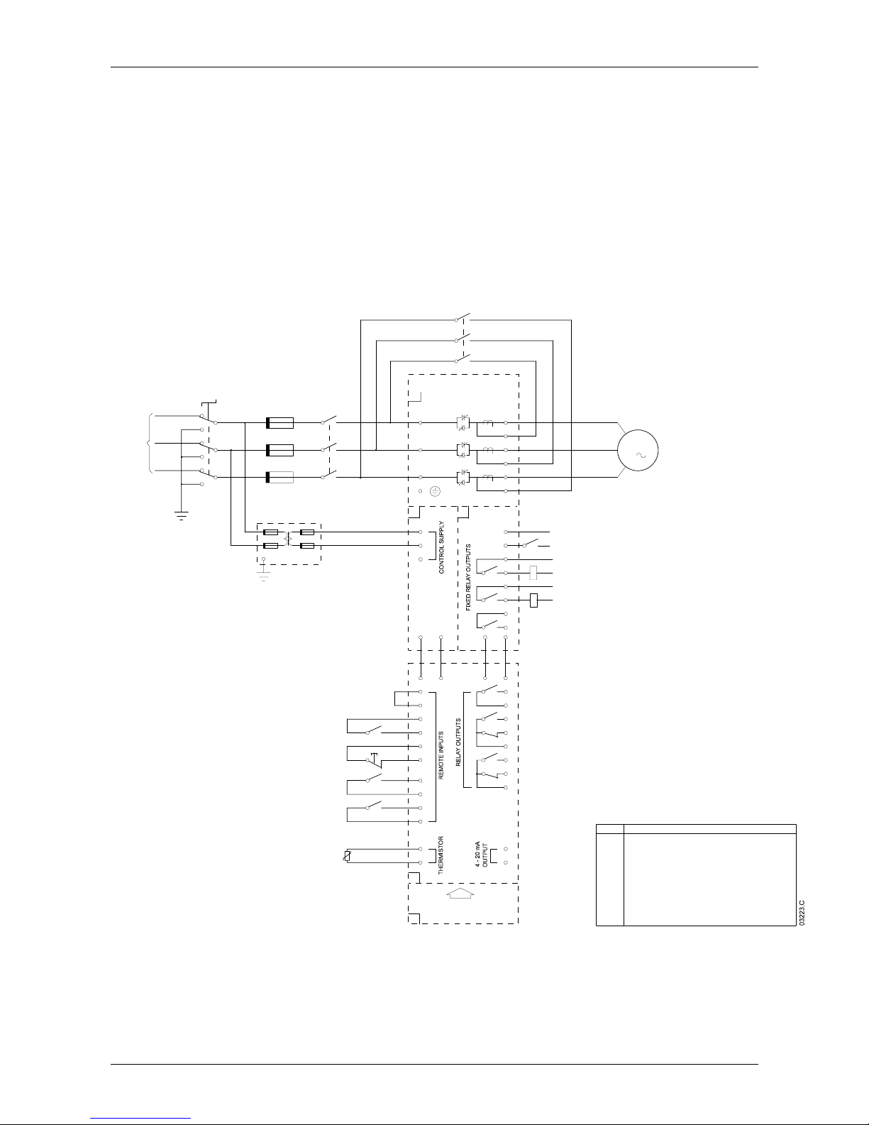
The MVS requires a low voltage control supply (110~130 VAC or 220~240 VAC).
If low voltage is not available, a transformer is required. Use a transformer with
primary voltage matching the mains voltage, and secondary voltage of 110 VAC.
Use a single phase 500 VA transformer with protection fuses on both the primary
and secondary sides (refer to
Diagram 2: Complete Power Circuit Configuration on
page 18).
Diagram 2: Complete Power Circuit Configuration
MVS power circuit with main contactor, bypass contactor, main isolator/ earth
switch, R Rated fuses and control supply transformer. Configured for two-wire
start/ stop control.
(110 VAC SECONDARY)
REMOTE RESET PUSHBUTTONS1
START/STOP SIGNALK1A
S1
K1A
- 15
+ 10
T3B
CONTROL SUPPLY TRANSFORMERPT2
PT2
110 VA C
(Wh)(Bk)
(Bk)(Wh)
MAIN ISOLATOR/EART H SWITCH
BYPASS CONTACTOR
MAIN CONTACTOR
R RATED PROTECTION FUSES
COMMS MODULE (OPT IONAL)
CONTROLLER
POWER INTERFACE PCB
CONTROL VOLTAGE TERMINAL BLOCK
POWER ASSEMBLY
DESCRIPTION
Q1
K2M
K1M
F1
A6
A4
A3
A2
A1
ITEM
A6
A4
A3
A2
A1
Q1
F1
50/60 Hz
K2M
T1B
T2B
E
L1
L2
L3
PROGRAMMABLE
INPUT A
PROGRAMMABLE
T1
T2
T3
A1
A2
A3
C23
C24
C31
C32
START/STOP
RESET
INPUT B
C53
C54
C63
C64
MOTOR
THERMISTOR
COMMS MODULE
(OPTIONAL)
B4
B5
13
14
23
24
43
44
54
52
51
64
62
61
PROGRAMMABLE
OUTPUT A
PROGRAMMABLE
OUTPUT B
PROGRAMMABLE
OUTPUT C
B10
B11
PROGRAMMABLE
ANALOG OUTPUT
C41
C42
C73
C74
BYPASS CONTACTOR
FEEDBACK SIGNAL
(PFC)
RUN OUTPUT
34
33
+
-
A11 A12
A11 A12
TX RX
RX TX
K2M
K1M
K2M BYPASS CONTACTOR
K1M MAIN CONTACTOR
3
M
SUPPLY
3 PHASE
MOTOR
Page 20
INSTALLATION: POWER CIRCUITS
MVS Series 19 710-03261-00D
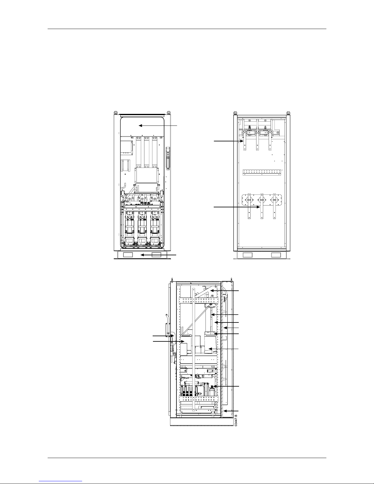
5.10 Enclosures
MVS soft starters can be installed easily into standard enclosures to provide a
complete motor control cabinet. The compact size of the power assembly leaves
room for auxiliary equipment to be installed.
The power assembly should be mounted at the bottom of the enclosure, and the
MVS Controller can be mounted on the front panel. The diagrams below illustrate
one possible configuration for installation.
Front View
Welded steel plinth
Earth switch viewing window
Rear View
Line bus bars
Motor bus bars
Side View
Interlock mechanism
Fuses
Main contactor
Rear cabling cavity
Power assembly
Bypass contactor
Low voltage trunking
Control voltage transformer
Metering/ protection transformer
Main isolator/ earth switch
Page 21
INSTALLATION: CONTROL CIRCUITS
710-03261-00D 20 MVS Series
Control Circuits
6
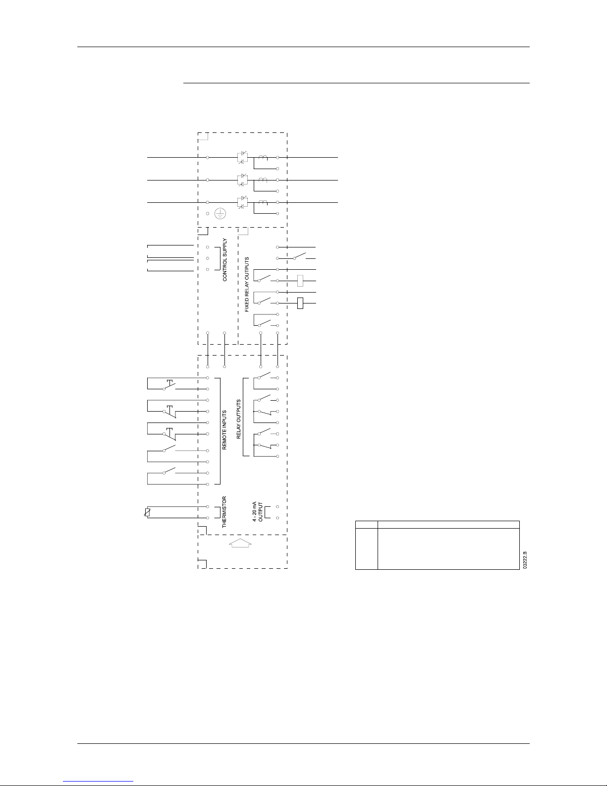
6.1 Electrical Schematic
Diagram 3: Electrical Schematic
K2M
BYPASS CONTACTOR
MAIN CONTACTOR
E
A3A2
TO MOTOR
SUPPLY
3 PHASE
ITEM
A1
A2
A3
A4
A6
K1M
K2M
DESCRIPTION
POWER ASSE MBLY
CONTROL VOLTAGE TERMINAL BLOCK
POWER INTERFACE PCB
CONTROLLER
COMMS MODULE (OPTIONAL)
MAIN CONTACTOR
BYPASS CONTACTOR
T3
T2
T1
L3
L2
L1
T3B
T2B
T1B
A1
K1M
K2M
110~130 VAC
220~240 VAC
- 15
+ 10
- 15
+ 10
TXRX
RXTX
A12A11
A12A11
-
+
33
34
RUN OUTPUT
(PFC)
FEEDBACK SIGNAL
BYPASS CONTACTOR
C74
C73
C42
C41
ANALOG OUTPUT
PROGRAMMABL E
B11
B10
OUTPUT C
PROGRAMMABL E
OUTPUT B
PROGRAMMABL E
OUTPUT A
PROGRAMMABL E
61
62
64
51
52
54
44
43
24
23
14
13
B5
B4
(OPTIONAL)
COMMS MODULE
THERMISTOR
MOTOR
C64
C63
C54
C53
INPUT B
RESET
STOP
START
C32
C31
C24
C23
A3
A2
A1
PROGRAMMABLE
INPUT A
PROGRAMMABLE
A4
A6
(Wh) (Bk)
(Bk) (Wh)
Chapter 6
Page 22
INSTALLATION: CONTROL CIRCUITS
MVS Series 21 710-03261-00D
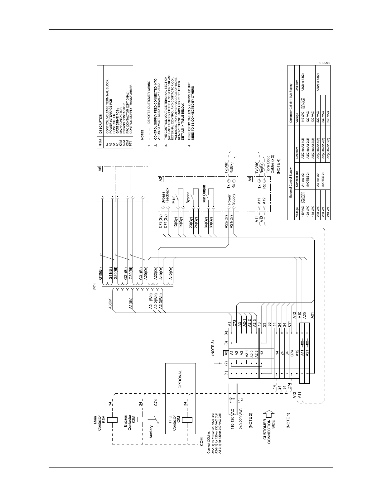
6.2 Internal Wiring
Diagram 4: Internal Wiring
Page 23
INSTALLATION: CONTROL CIRCUITS
710-03261-00D 22 MVS Series
6.3 Control Wiring
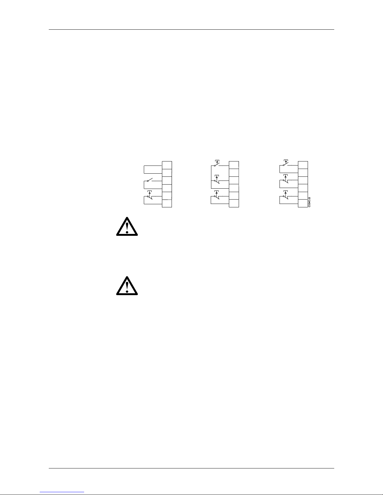
The soft starter's operation can be controlled in three ways:
• using the buttons on the MVS Controller
• via remote inputs
• via a serial communication link
The <LCL/RMT> button controls whether the MVS will respond to local control (via
the MVS Controller) or remote control (via the remote inputs). Serial
communication is always enabled in local control mode, and can be enabled or
disabled in remote control mode (refer to parameter 4-B).
The MVS has three fixed inputs for remote control. These inputs should be
controlled by contacts rated for low voltage, low current operation (gold flash or
similar).
Reset
Stop
Star t
C32
C31
C24
C23
C42
C41
Two wire control
Reset
Stop
Star t
C32
C31
C24
C23
C42
C41
Three wire control
Reset
Stop
Star t
C32
C31
C24
C23
C42
C41
Four wire control
start/stop
reset
start
stop
reset
start
stop
reset
CAUTION
Do not apply voltage to the control input terminals. These are active
24 VDC inputs and must be controlled with potential free circuits.
Ensure cables to the control inputs are segregated from AC power and
control wiring.
CAUTION
The <STOP> button on the MVS Controller is always enabled. When
using two-wire remote control, the soft starter will restart immediately if
the remote start input is still active.
Page 24
INSTALLATION: SETUP TOOLS
MVS Series 23 710-03261-00D
Setup Tools
7
MVS soft starters offer programming and simulation features specifically designed
to make commissioning safe and easy.
7.1 Simulation Tools
Software simulation functions allow the MVS to be tested without a motor
connected, to confirm that the soft starter's control circuits are operating correctly.
There are three simulation modes available:
• Run simulation: simulates a motor starting, running and stopping to confirm
that the soft starter has been installed correctly.
• Protection simulation: simulates activation of each protection mechanism to
confirm that the soft starter is responding correctly in each situation.
• Signalling simulation: simulates output signalling to confirm that outputs are
operating correctly.
For details of the simulation functions, refer to
Commissioning Menu: Simulation
Tools
on page 30.
7.2 Low Voltage Test Mode
The MVS can be connected to a low voltage motor (≤ 500 VAC) for testing. This
allows the user to thoroughly test the soft starter and its associated power and
control circuits. The low voltage test mode provides a means of testing the soft
starter's configuration without requiring a full medium voltage test facility. To
perform the low voltage test, one non-conduction resistor assembly must be
connected to each phase arm (three resistor assemblies are supplied with the soft
starter).
During the low voltage test, the soft starter's input, output and protection settings
can be tested. Low voltage mode is not suitable for testing soft starting or soft
stopping performance.
To operate the MVS in low voltage test mode:
1. Isolate the soft starter from the motor and the mains supply.
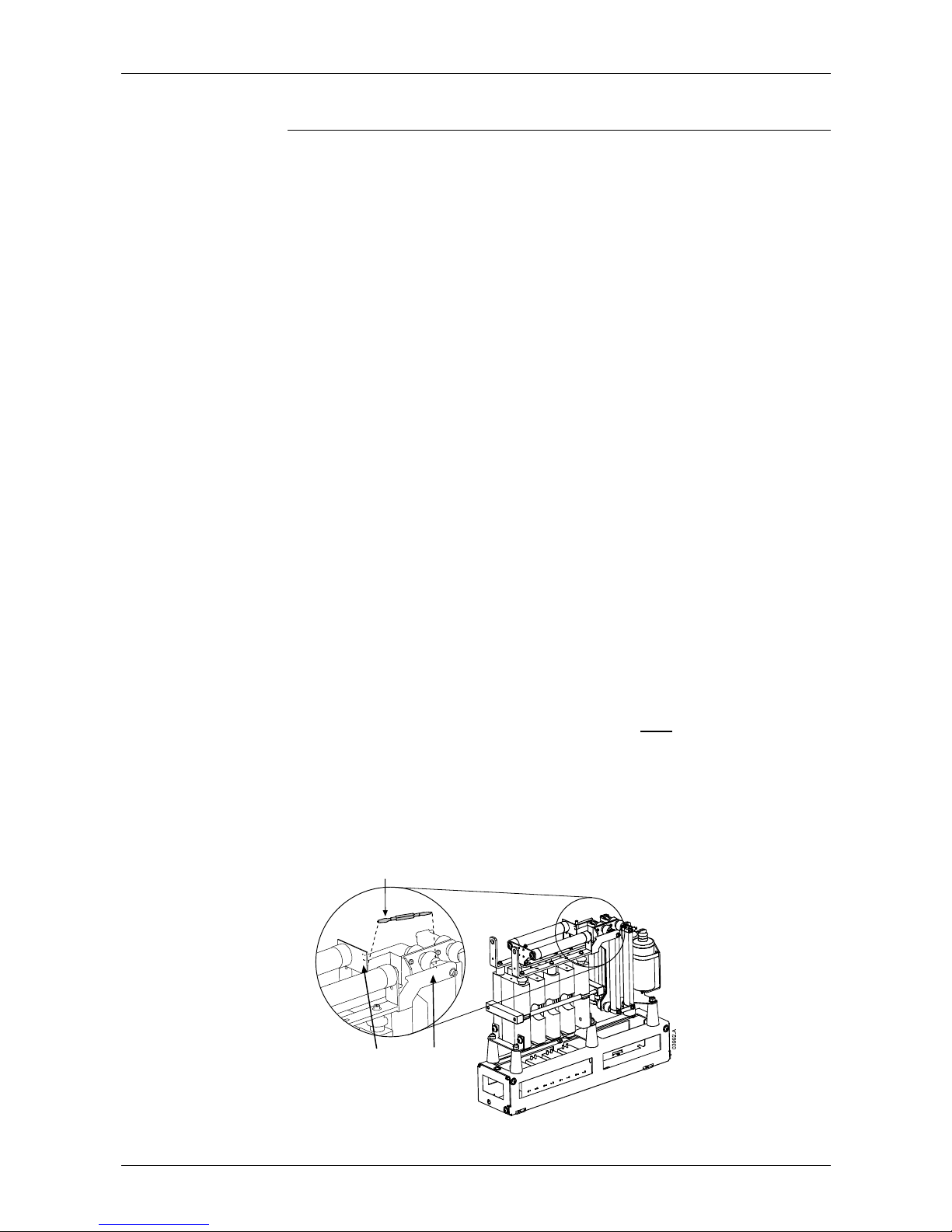
2. Connect one non-conduction resistor assembly to each
phase arm.
For V02, V03 and V04 units:
Clip one end of the resistor assembly to the plated hole on the non-conduction
PCB. The non-conduction PCB is located at the top of the phase arm, behind
the long round grading resistor (on the left hand side when viewed from the
front). Clip the other end of the resistor assembly to any point on the steel
bracket behind the other grading resistor.
Non-conduction
PCB
Non-conduction
resistor assembly
Steel
bracket
Chapter 7
Page 25
INSTALLATION: SETUP TOOLS
710-03261-00D 24 MVS Series
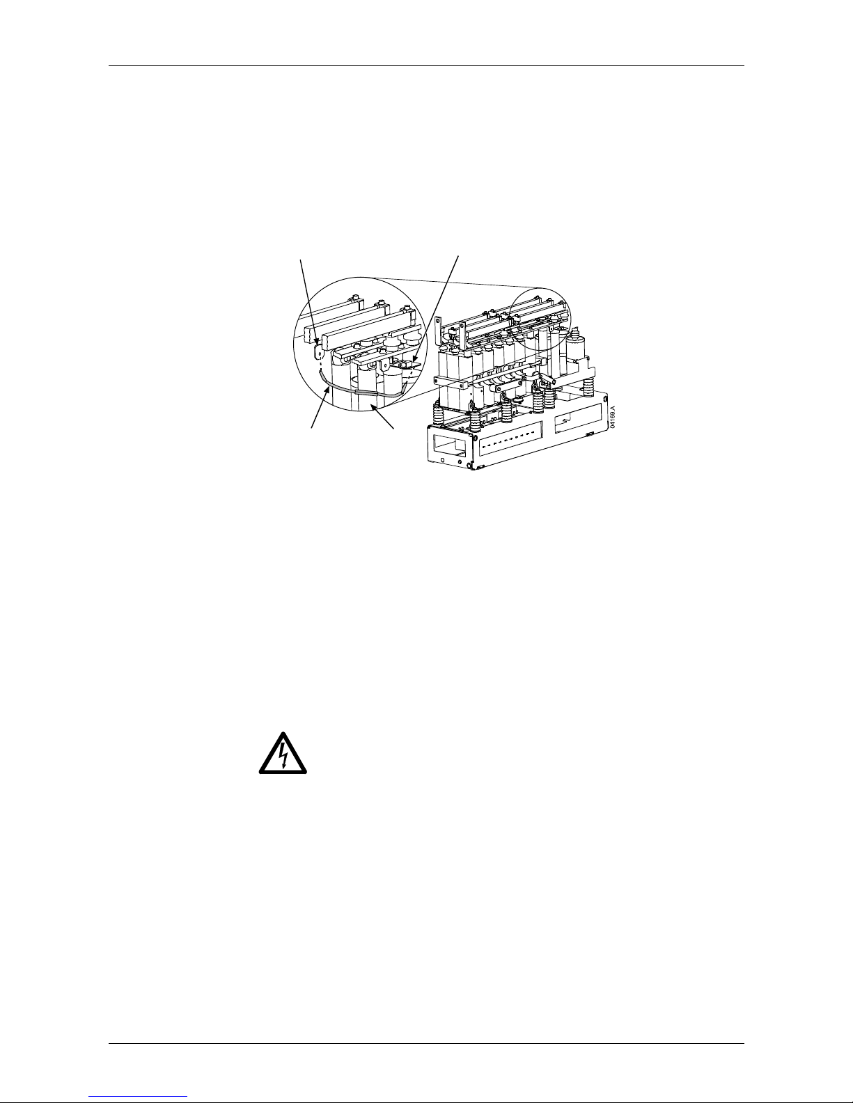
For V06 and V07 units:
Clip one end of the resistor assembly to the plated hole on the non-conduction
PCB. The non-conduction PCB is located on the side of the phase arm, at the
top of the long round grading resistor (on the right hand side when viewed from
the front). There is a small steel bracket just in front of the PCB. Pass the
other end of the resistor assembly through the phase arm, in front of the three
grading resistors, and clip it to the steel bracket in front of the grading resistor
on the other side of the phase arm (this bracket looks the same as the bracket
in front of the non-conduction PCB).
Non-conduction
PCB
Non-conduction
resistor assembly
Stee l
bracket
Grading
resistors
3. Connect T1, T2, T3 of the soft starter to a three phase motor with full load
current greater than 5 A. Connect L1, L2, L3 of the soft starter to three phase
mains supply with voltage less than 500 VAC (frequency 50 Hz or 60 Hz).
4. Set parameter 1-A
Motor Full Load Current to the value shown on the motor
name plate. Set parameters 3-U
Overvoltage Level and 3-W Undervoltage
Level to suit the low voltage mains supply.
5. Switch on control and mains supply, and use the MVS to start the motor. The
start command can be sent from the MVS Controller or via the remote input.
Monitor the soft starter's display and verify the line voltage readings.
6. Stop and restart the motor several times to confirm correct and consistent
operation.
7. When testing is complete, isolate the soft starter from the mains supply.
Disconnect the soft starter from the motor and mains voltage, then remove
control voltage. Remove the non-conduction resistor assembly from each
phase arm.
WARNING
After low voltage mode testing, ensure that the non-conduction resistor
assembly is removed from each phase arm before connecting the soft
starter to a medium voltage motor. If the non-conduction resistor
assemblies remain on the phase arms, the soft starter may suffer severe
damage.
Page 26

OPERATION: KEY FEATURES
MVS Series 25 710-03261-00D
Operation
Key Features
MVS soft starters offer several special functions to ensure ease of use and to
provide optimal motor control in all environments and applications.
Dual Parameter Set
The MVS can be programmed with two separate sets of operating parameters.
This allows the soft starter to control the motor in two different starting and stopping
configurations.
The secondary motor settings (parameter groups 12 and 13) are ideal for slip-ring
motors, dual speed motors, or conventional (squirrel-cage) motors which may start
in two different conditions (such as loaded and unloaded conveyors).
NOTE
MVS soft starters are not suitable for controlling two separate motors.
The secondary parameter set should only be used for a secondary
configuration of the primary motor.
Customisable Protection
The MVS offers comprehensive protection to ensure safe operation of the motor
and soft starter. The protection characteristics can be customised extensively to
match the exact requirements of the installation.
Advanced Thermal Modelling
Intelligent thermal modelling allows the soft starter to predict whether the motor can
successfully complete a start. The MVS uses information from previous starts to
calculate the motor's available thermal capacity, and will only permit a start which
is predicted to succeed.
Comprehensive Event and Trip Logging
The MVS has a 99-place event log to record information on soft starter operation.
A separate trip log stores detailed information about the last eight trips.
Informative Feedback Screens
A large-format screen allows the MVS to display important information clearly.
Comprehensive metering information, details of starter status and last start
performance allow easy monitoring of the starter's performance at all times.
Section 3
Page 27
OPERATION: USER INTERFACE
710-03261-00D 26 MVS Series
User Interface
8
8.1 MVS Controller
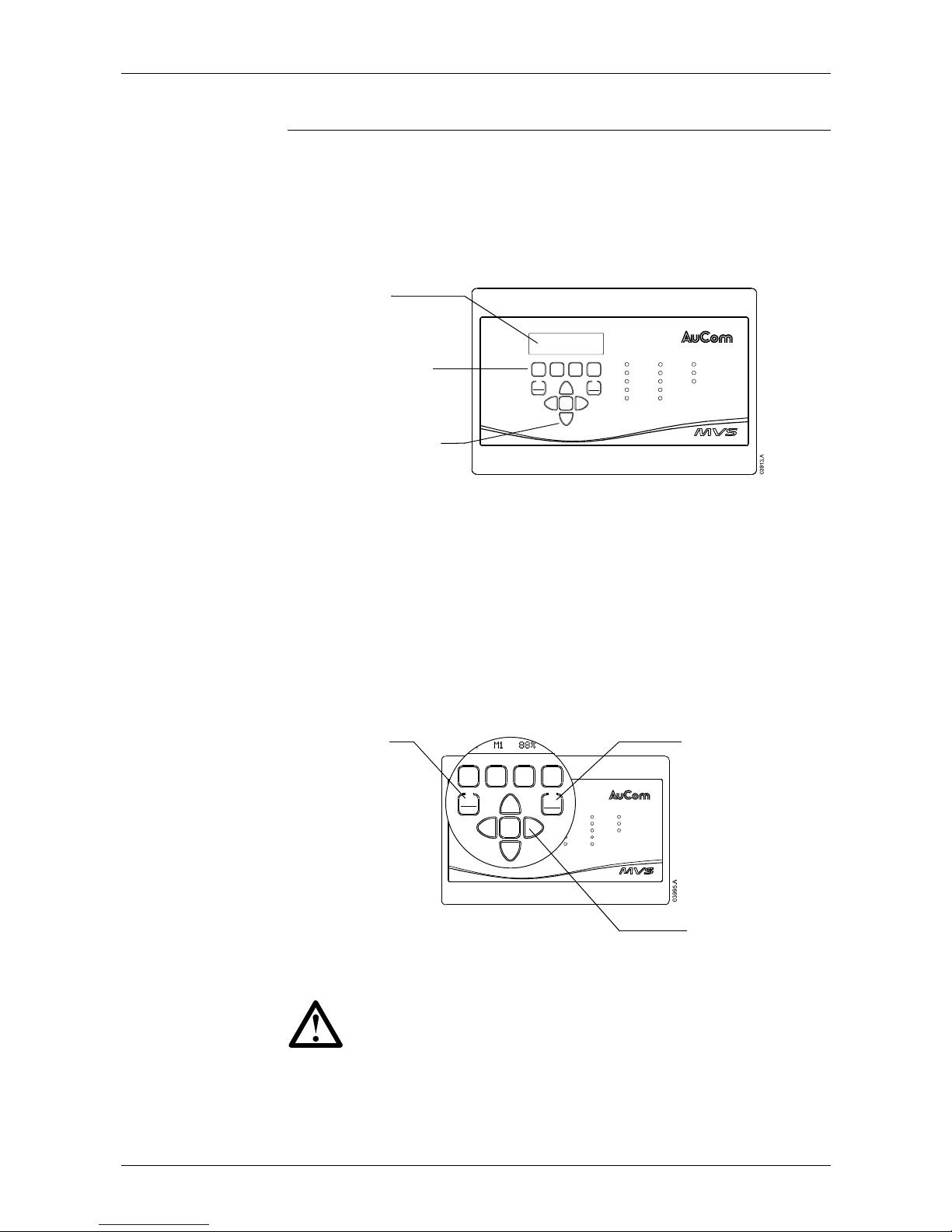
The MVS Controller provides a complete user interface for interacting with MVS
soft starters.
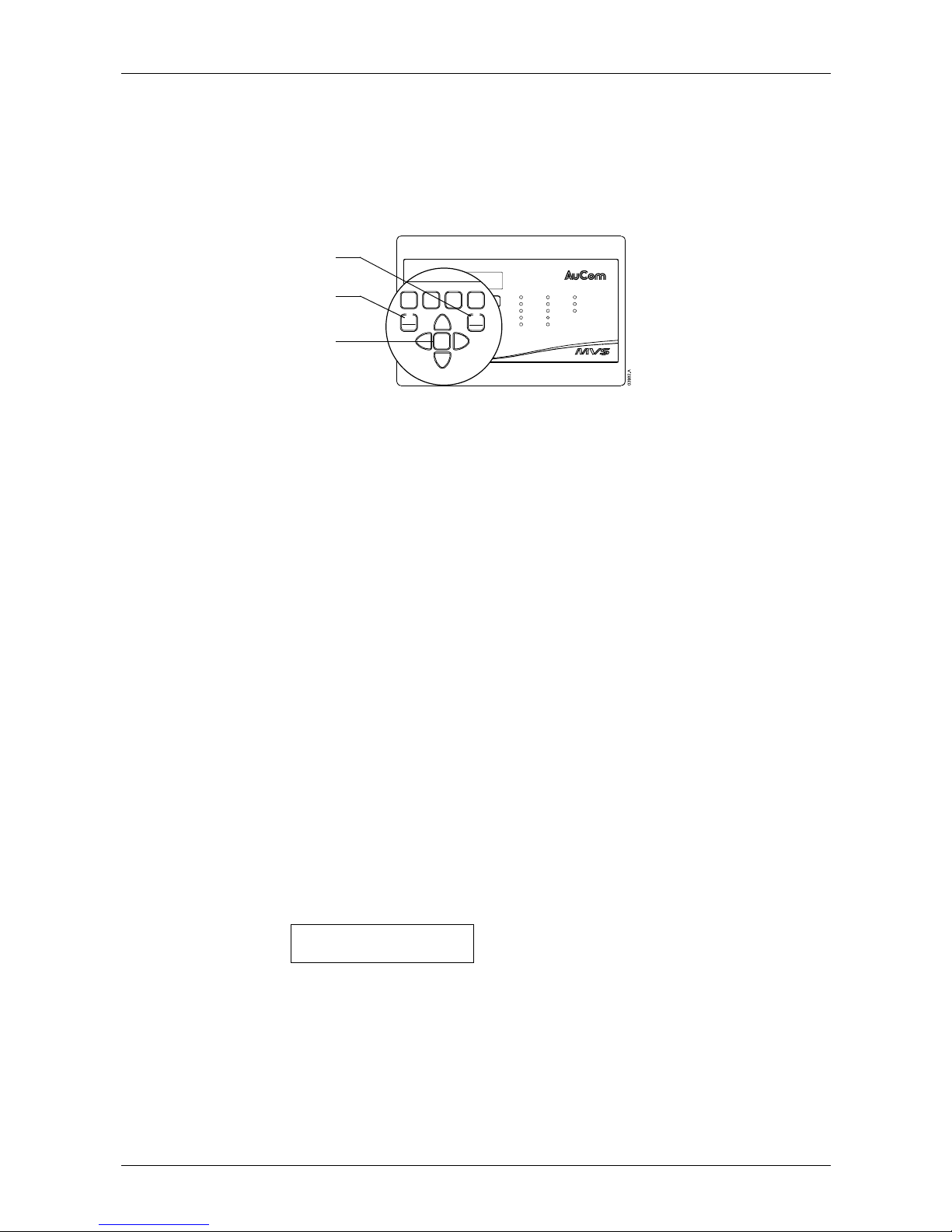
The MVS Controller has four navigation buttons and seven function buttons which
are used to control the motor, access operating information, and program the soft
starter.
Navigation buttons
Function buttons
Display
Start
Stop
Reset
Input A
Input B
Start
Run
Trip
Warning
Remote
RLA
RLB
RLC
Series
START
LCL/
RMT
F1
LOGS
UNDO
STOP RESET
F2
SETUP
TOOLS
STORE
Fn
Starter
Status
Control
Inputs
Relay
Outputs
8.2 Menus
Configuration and control of the soft starter is managed via the MVS Controller.
Information is arranged in three menus:
• The Programming Menu provides access to all programmable parameters.
The Programming Menu is accessed by pressing the ► button while viewing
the metering screens.
• The Commissioning Menu provides access to tools which assist setup when
the soft starter is deployed. The Commissioning Menu is accessed by pressing
the <
SETUP TOOLS> button while viewing the metering screens.
• The Logs Menu provides viewing access to the Event and Trip Logs and the
soft starter's performance counters. The Logs Menu is accessed by pressing
the <
LOGS> button while viewing the metering screens.
Start
Stop
Reset
Input A
Input B
Start
Run
Trip
Warning
Remote
RLA
RLB
RLC
Series
START
LCL/
RMT
F1
LOGS
UNDO
STOP RESET
F2
SETUP
TOOLS
STORE
Fn
Starter
Status
Control
Inputs
Relay
Outputs
RUNNING STOP IN 14:02
260a M1 88%
START
LCL/
RMT
F1
LOGS
UNDO
STOP RESET
F2
SETUP
TOOLS
STORE
Fn
Open the Logs Menu
Open the Commissioning Menu
Open the Programming Menu
Navigation
NOTE
The menus can only be accessed from the metering screens. You
cannot open a menu from inside another menu.
Use the ▲ and ▼ buttons to scroll through the items in a menu.
To view the items in a sub-menu, press the ► button. To close the sub-menu and
return to the previous level, press ◄.
Chapter 8
Page 28
OPERATION: USER INTERFACE
MVS Series 27 710-03261-00D
Menu Shortcuts
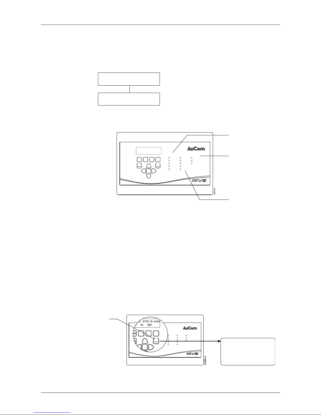
The MVS Controller offers keyboard shortcuts for fast access to commonly used
parameters. Use parameters 11-B and 11-C (
F1 and F2 Pushbutton Function) to
select the shortcut target.
To use the shortcuts, press the <
FN> button and either the <F1> (<LOGS>) or
<
F2> (<SETUP TOOLS>) button at the same time.
Start
Stop
Reset
Input A
Input B
Start
Run
Trip
Warning
Remote
RLA
RLB
RLC
Series
START
LCL/
RMT
F1
LOGS
UNDO
STOP RESET
F2
SETUP
TOOLS
STORE
Fn
Starter
Status
Control
Inputs
Relay
Outputs
START
LCL/
RMT
F1
LOGS
UNDO
STOP RESET
F2
SETUP
TOOLS
STORE
Fn
F1 button
Fn button
F2 button
Altering Parameter Values
To change a parameter value, scroll to the appropriate parameter in the
Programming Menu and press the ► button to enter edit mode.
• To alter the parameter value, use the ▲ and ▼ buttons. Pressing the ▲ or ▼
button once will increase or decrease the value by one (1). If the button is held
for longer than five seconds, the value will increase or decrease at a faster
rate.
• To save changes, press the <STORE> button. The value shown on the
display will be saved and the MVS Controller will return to the parameter list.
• To cancel changes, press the <UNDO> button. The MVS Controller will return
to the currently saved setting.
• To end edit mode, press the ◄ button. The MVS Controller will return to the
parameter list and any unsaved changes will be lost.
You can access the Programming Menu at any time, including while the soft starter
is running. Any changes to the start profile take effect after the next start. All other
changes take effect immediately.
8.3 Security
Adjustment Lock
You can lock the Programming Menu to prevent users from altering parameter
settings. When the adjustment lock (parameter 20-B) is on, users have read-only
access to view parameter values in the Programming Menu, and the
Commissioning Menu is not available.
If a user attempts to change a parameter value or access the Commissioning
Menu, an error message is displayed:
Access Denied
Adj Lock is On
Authorised users can unlock the Programming Menu using parameter 20-B.
Security Access Code
In addition to the adjustment lock, critical parameters in the Programming Menu
(parameter group 20 and higher) are protected by a four-digit security access code,
preventing unauthorised users from viewing or modifying parameter settings.
When a user attempts to open parameter group 20, the MVS Controller prompts for
an access code. If the code that is entered matches the stored access code,
Page 29
OPERATION: USER INTERFACE
710-03261-00D 28 MVS Series
access is permitted. The security access code is requested once for the
programming session, and authorisation continues until the user closes the menu.
To enter the security access code, use the ◄ and ► buttons to select a digit, and
the ▲ and ▼ buttons to change the value. When all four digits match your access
code, press <
STORE> to submit the access code. The MVS Controller will display
an acknowledgement message before continuing.
Enter Access Code
1234
<STORE>
Access Allowed
Supervisor
8.4 LEDs
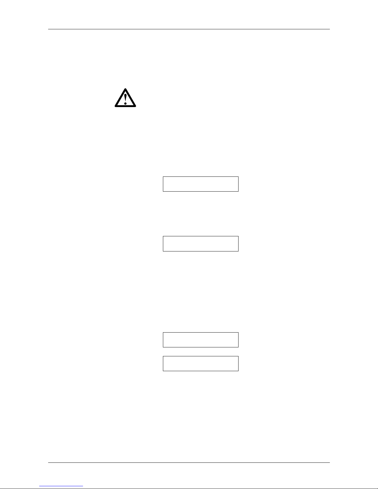
The MVS Controller has 13 LEDs for at-a-glance monitoring of starter status.
Starter status LEDs
Control input LEDs
Relay output LEDs
Start
Stop
Reset
Input A
Input B
Start
Run
Trip
Warning
Remote
RLA
RLB
RLC
Series
START
LCL/
RMT
F1
LOGS
UNDO
STOP RESET
F2
SETUP
TOOLS
STORE
Fn
Starter
Status
Control
Inputs
Relay
Outputs
The Starter Status LEDs report the operating status of the soft starter:
• The Start LED is on while the starter is starting, running or stopping.
• The Run LED is on while the starter is running.
• The Trip LED is on when a trip has occurred.
• The Warning LED is on while a warning is active.
• The Remote LED is on when remote mode is selected.
The Control Input LEDs activate when a signal is present at the corresponding
control terminals.
The Relay Output LEDs activate when the corresponding output relay is active.
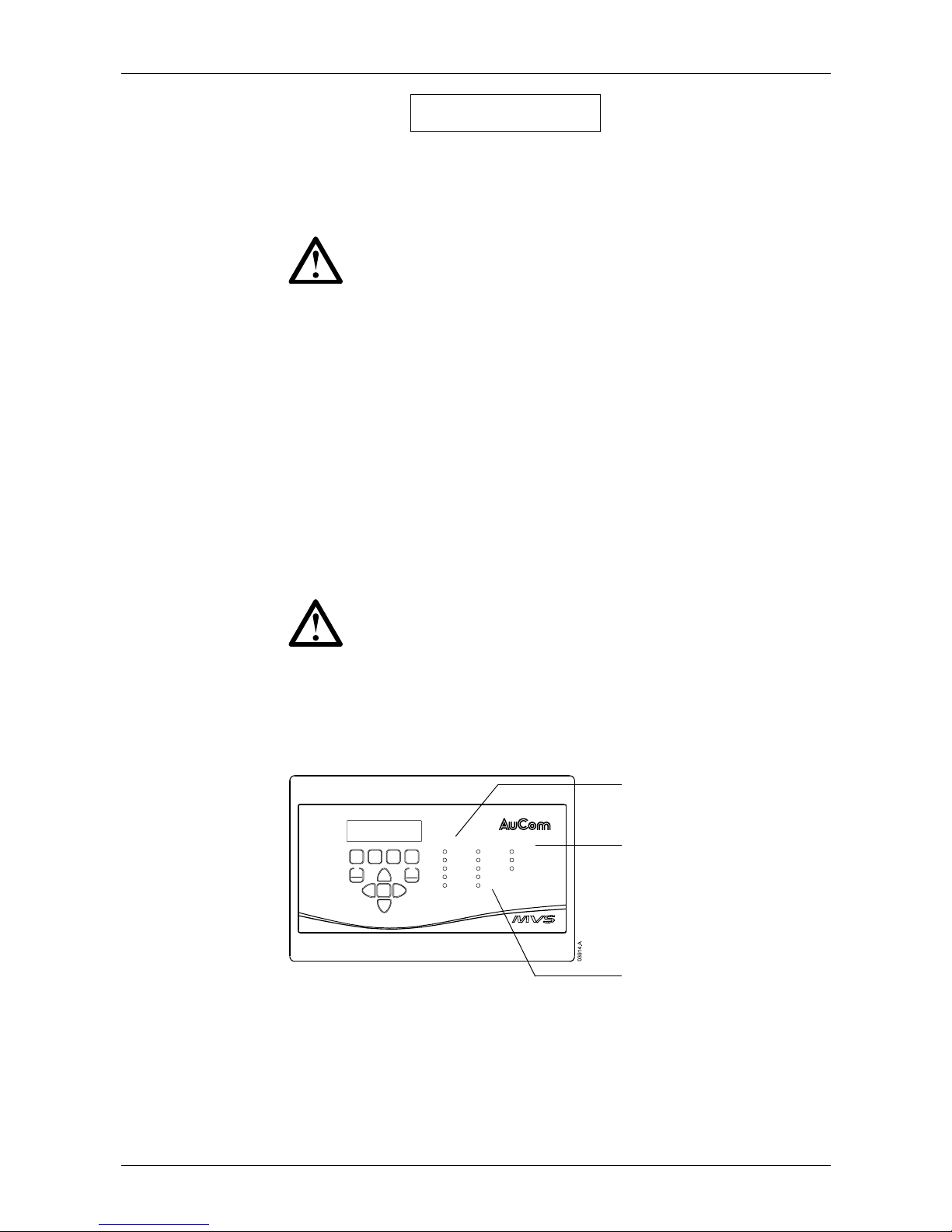
8.5 Commissioning Menu
The Commissioning Menu provides access to commissioning and testing tools.
To open the Commissioning Menu, press the <
SETUP TOOLS> button while
viewing the metering screens.
Start
Stop
Reset
Input A
Input B
Start
Run
Trip
Warning
Remote
RLA
RLB
RLC
Series
START
LCL/
RMT
F1
LOGS
UNDO
STOP RESET
F2
SETUP
TOOLS
STORE
Fn
Starter
Status
Control
Inputs
Relay
Outputs
RUNNING STOP IN 14:02
260a M1 88%
LCL/
RMT
STOP RESET
F2
SETUP
TOOLS
STORE
Fn
Setup Tools
button
Commissioning Menu
Reset Thermal Models
Parameter Archive
Run Simulation
Protection Simulation
Output Signal Simulation
Page 30
OPERATION: USER INTERFACE
MVS Series 29 710-03261-00D
To navigate through the Commissioning Menu:
• to scroll the next or previous item, press the ▲ or ▼ button
• to open an item for viewing, press the ► button
• to return to the previous level, press the ◄ button
• to close the Commissioning Menu, press the <SETUP TOOLS> button.
NOTE
The Commissioning Menu is only available if the Programming Menu is
unlocked (parameter 20-B
Adjustment Lock is set to Off).
Thermal Model Reset
The soft starter's advanced thermal modelling software monitors the motor's
performance during each start and throughout the running cycle. This allows the
soft starter to calculate the motor's temperature and ability to start successfully at
any time.
The soft starter's thermal model can be reset if required.
Reset Thermal Models
Reset >
In order to reset the thermal model, press the ► button. At the confirmation
prompt, press <
STORE> to confirm or <UNDO> to cancel the action. Cancelling
the action returns to the Commissioning Menu.
When the thermal model has been reset, the screen will briefly display a
confirmation message, then return to the previous screen.
Reset Thermal Models
Reset
Parameter Archive
The parameter archive menu allows users to:
• restore the MVS to factory default settings
• save the current parameter settings to an internal file
• reload parameter settings from an internal file
The MVS can store two separate user-defined files.
1. To select a parameter archive function, scroll to the Parameter Archive screen
in the Commissioning Menu then press the ► button.
Parameter Archive
Load/Save >
2. Use the ▼ button to select the desired function.
Load Defaults
Load >
The options are:
• Load defaults
• Load user set 1
• Load user set 2
• Save user set 1
• Save user set 2
3. When the screen shows the required function, press the ► button. The MVS
will prompt for confirmation.
Page 31
OPERATION: USER INTERFACE
710-03261-00D 30 MVS Series
Save User Set 1
Ok/STORE
4. Press <STORE> to confirm or <UNDO> to cancel the action. Cancelling the
action returns to the previous screen.
When the action has been completed, the display will briefly confirm success
then return to the main status screen.
NOTE
The default values saved in user set 1 and user set 2 are the same as the
default values for each parameter.
Simulation Tools
Software simulation functions allow the user to test the soft starter's operation
without applying voltage to the motor. This allows the user to test control circuits
and associated equipment. There are three simulation modes available:
• Run simulation: simulates a motor starting, running and stopping to confirm
that the soft starter has been installed correctly.
• Protection simulation: simulates activation of each protection mechanism to
confirm that the soft starter is activating correctly in each situation.
• Signalling simulation: simulates output signalling to confirm that outputs are
operating correctly.
The simulation tools can be accessed via the Commissioning Menu. Press the
<
SETUP TOOLS> button then use the ▼ button to scroll through the menu to the
required simulation.
NOTE
The simulation tools are only available if the Programming Menu is
unlocked (parameter 20-B
Adjustment Lock is set to Off).
• Run Simulation
The MVS Controller allows the user to simulate a motor starting, running and
stopping, in order to confirm that the soft starter and any auxiliary switchgear have
been installed correctly. Feedback is provided via the display and the status LEDs.
Starter status LEDs
Control input LEDs
Relay output LEDs
Start
Stop
Reset
Input A
Input B
Start
Run
Trip
Warning
Remote
RLA
RLB
RLC
Series
START
LCL/
RMT
F1
LOGS
UNDO
STOP RESET
F2
SETUP
TOOLS
STORE
Fn
Starter
Status
Control
Inputs
Relay
Outputs
The run simulation provides a safe method of confirming that the installation is
operating as expected. The simulation is particularly useful to confirm the correct
configuration of the main and bypass contactors, fibre-optic controls and
programmable outputs.
The simulation can be terminated at any time by pressing the <
UNDO> button.
The MVS Controller will return to the Commissioning Menu.
Page 32
OPERATION: USER INTERFACE
MVS Series 31 710-03261-00D
NOTE
During the simulation, no pre-start checks are made and the soft starter
must be disconnected from mains voltage. The MVS Controller must be
connected to the low voltage control supply.
The simulation is only available when the soft starter is in Ready state.
To activate the run simulation:
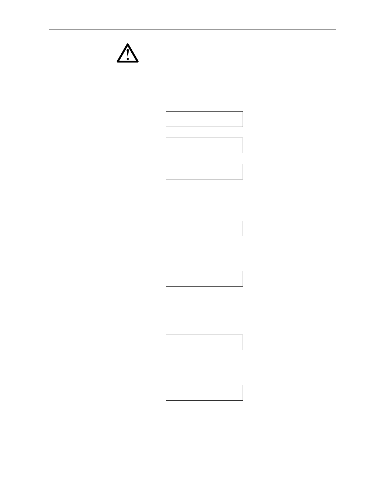
1. Open the Commissioning Menu and select Run Simulation.
Simulation Mode
Run sim >
2. To enter the run simulation, press the ► button.
Ready
Wait for start sig
3. Press the <START> button.
Pre-Start Checks
>
The soft starter will perform its pre-start checks. If parameter 5-D (Output
Relay A Functionality) is set to Main Contactor, the Relay A LED on the MVS
Controller activates.
4. Press the ► button to proceed to the next stage of the simulation. The MVS
simulates starting.
Starting – Phase 1
>
The Start LED activates on the MVS Controller and the Phase 1 firing LED
blinks on the power interface PCB.
5. Press the ► button to proceed to the next stage of the simulation. The MVS
simulates running.
Running – Phase 2
Wait for Stop Signal
The bypass contactor closes and the Run LED activates on the MVS
Controller. The Phase 2 firing LED blinks on the power interface PCB. If
parameter 5-G (
Output Relay B Functionality) is set to Run, the Relay B LED
on the MVS Controller activates.
6. Press the <
STOP> button to proceed to the next stage of the simulation. The
MVS simulates stopping.
Stopping - Phase 3
>
The bypass contactor opens and the Run and Relay B LEDs on the MVS
Controller turn off. The Phase 3 firing LED blinks on the power interface PCB.
7. Press the ► button to proceed to the next stage of the simulation. The MVS
returns to the stopped state.
Stopped
>
The main contactor opens and all LEDs turn off.
8. Press the ► button to terminate the simulation and return to the
Commissioning Menu.
Page 33
OPERATION: USER INTERFACE
710-03261-00D 32 MVS Series
• Protection Simulation
The MVS Controller allows the user to simulate activation of each protection
mechanism, in order to confirm that the soft starter is responding to each situation
correctly.
NOTE
During the simulation, no pre-start checks are made and the soft starter
must be disconnected from mains voltage. The MVS Controller must be
connected to the low voltage control supply.
The simulation is only available when the soft starter is in Ready state.
The protection simulation allows the user to confirm that protection events are
being reported correctly on the display and across the communication network.
To activate the protection simulation:
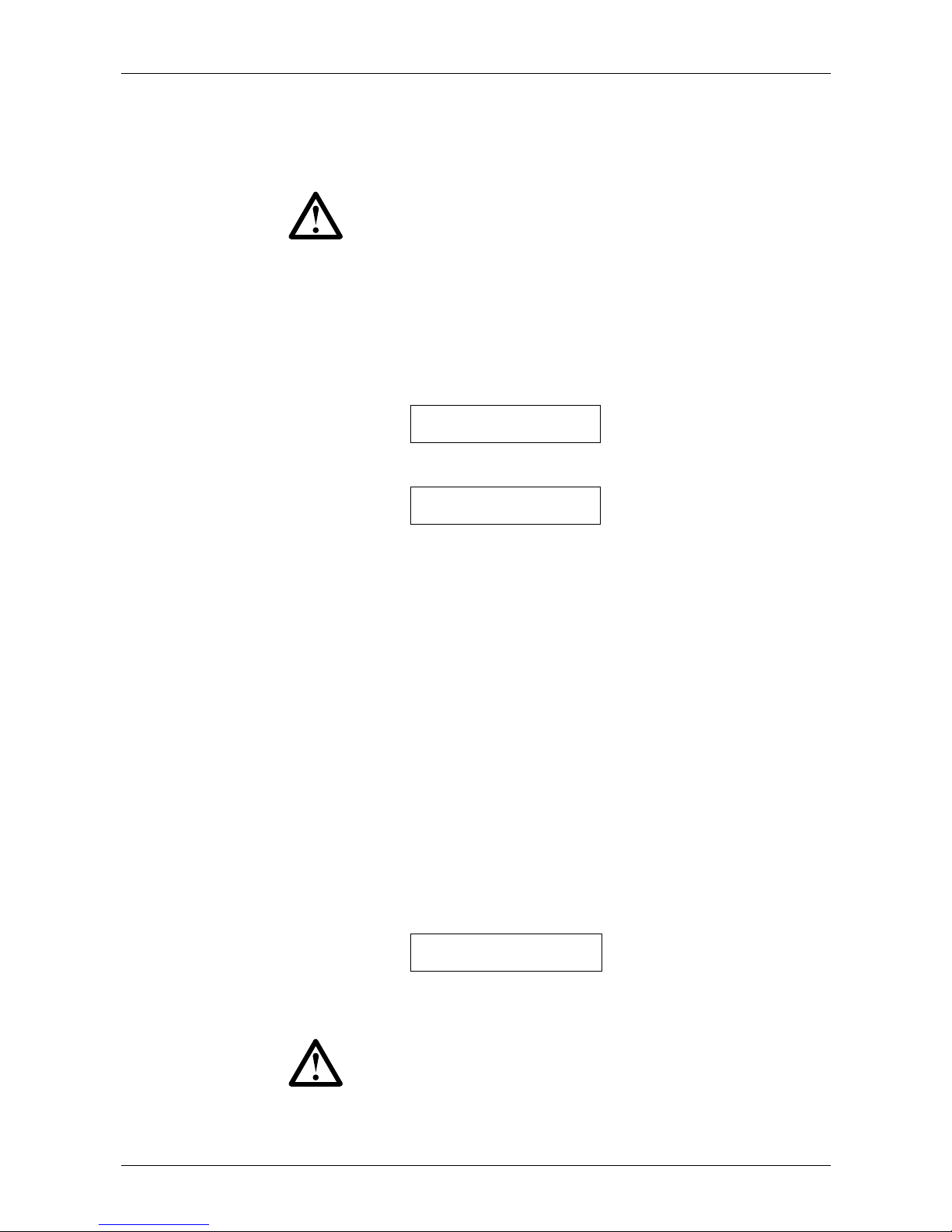
1. Open the Commissioning Menu and select Protection Simulation.
Simulation Mode
Protection sim >
2. Press the ► button to open the protection list. The display will indicate the first
simulation in the list.
Current Imbalance
Simulate >
3. Use the ▲ and ▼ buttons to select a protection to simulate. The following
protection conditions are available to simulate:
Motor overload
Undercurrent
Instantaneous overcurrent
Current imbalance
Mains frequency
Auxiliary trip A
Auxiliary trip B
Motor thermistor
Excess start time
Starter communication failure
Battery/ Clock failure
SCR temperature model
Network communication failure
Ground fault
Overvoltage
Undervoltage
Time-overcurrent
4. Hold down the ► button to simulate the selected protection. The simulation
will continue as long as the button is held down. The soft starter's response
depends on the protection class setting (parameter group 21).
Tripped
Current Imbalance
Release the ► button to end the simulation. Use ▲ or ▼ to select another
simulation, or press ◄ to return to the Commissioning Menu.
NOTE
If the protection class is set to Trip, reset the soft starter before
simulating another protection. If the protection class is set to
Warning or Log, no reset is required.
Page 34
OPERATION: USER INTERFACE
MVS Series 33 710-03261-00D
• Signalling Simulation
The MVS Controller allows the user to simulate output signalling in order to confirm
that the outputs are operating correctly.
NOTE
During the simulation, no pre-start checks are made and the soft starter
must be disconnected from mains voltage. The MVS Controller must be
connected to the low voltage control supply.
The simulation is only available when the soft starter is in Ready state.
To activate the signalling simulation:
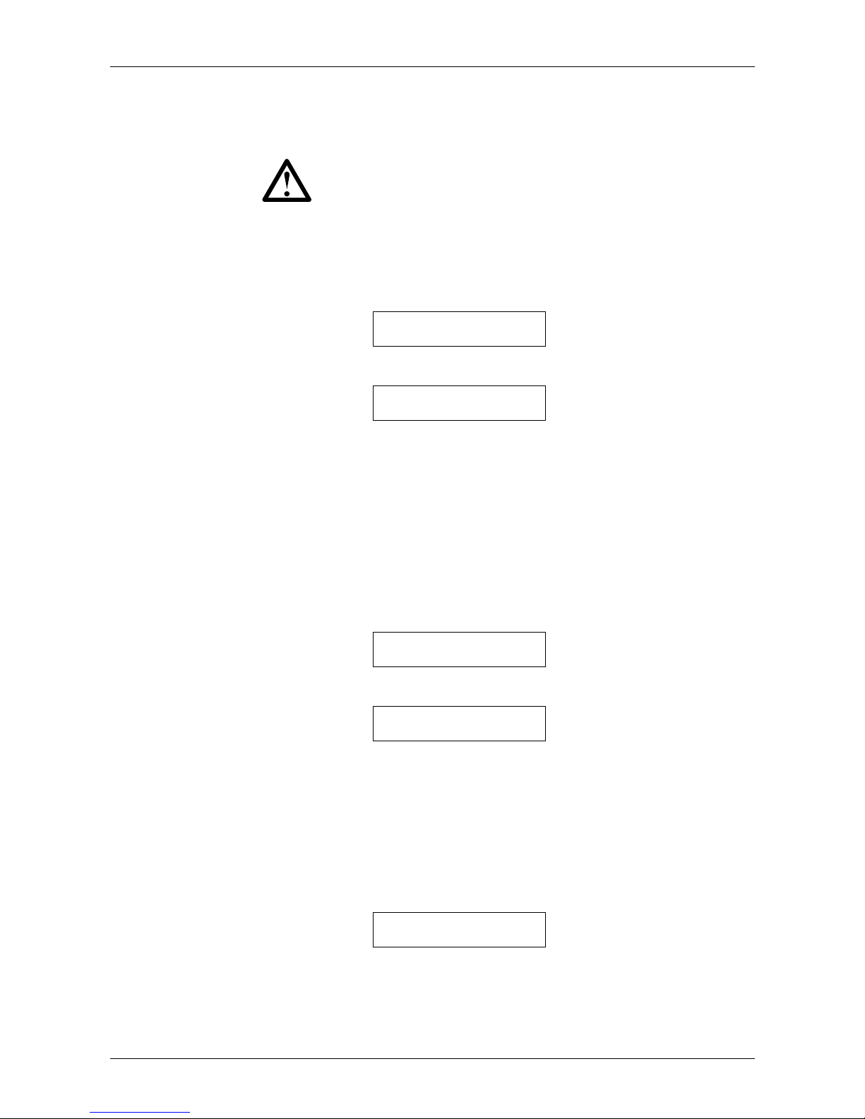
1. Open the Commissioning Menu and select Signalling Simulation.
Simulation Mode
Output Signal Sim >
2. Press the ► button to open the simulation list. The display will indicate the first
simulation in the list.
Analog Output
Simulate >
3. Use the ▲ and ▼ buttons to select a simulation. The following signals are
available to simulate:
Analog output
Low current flag
1
High current flag
1
Motor temperature flag
1
Relay A
Relay B
Relay C
1
To test the flags, set an output relay (parameters 5-A to 5-C) to the
appropriate function and monitor the relay's behaviour.
4. Once the required simulation is displayed, press ► to confirm the selection.
Low Current Flag
Simulate >
5. Press the ▲ button to start the simulation. Pressing the ▼ button stops the
signal.
Low Current Flag
▲ On ▼ Off
While the signal is being simulated, the display will indicate On. While the
signal is not being simulated, the display will indicate Off.
6. Once the simulation is complete, press ◄ to return to the simulation list.
Press ▲ or ▼ to select another simulation, or press ◄ again to return to the
Commissioning Menu.
Analog Output Simulation
The analog output simulation uses the ▲ and ▼ buttons to change the analog
output current at terminals B10, B11 of the MVS Controller.
Analog Output
0% 4 mA
Attach an external current measuring device to terminals B10, B11 of the MVS
Controller. Use the ▲ or ▼ button to adjust the percentage value in the lower left
hand corner of the display. The current measuring device should indicate the
same level of current as shown at the lower right corner of the display.
Page 35
OPERATION: USER INTERFACE
710-03261-00D 34 MVS Series
8.6 Programming Menu
The Programming Menu provides access to programmable parameters.
To open the Programming Menu, press the ► button while viewing the metering
screens.
Items in the Programming Menu are grouped into sets of related parameters. Use
the ▲ and ▼ buttons to move between parameters groups and between the
parameters in each group.
The security access code must be entered to access parameters in parameter
group 20 or higher.
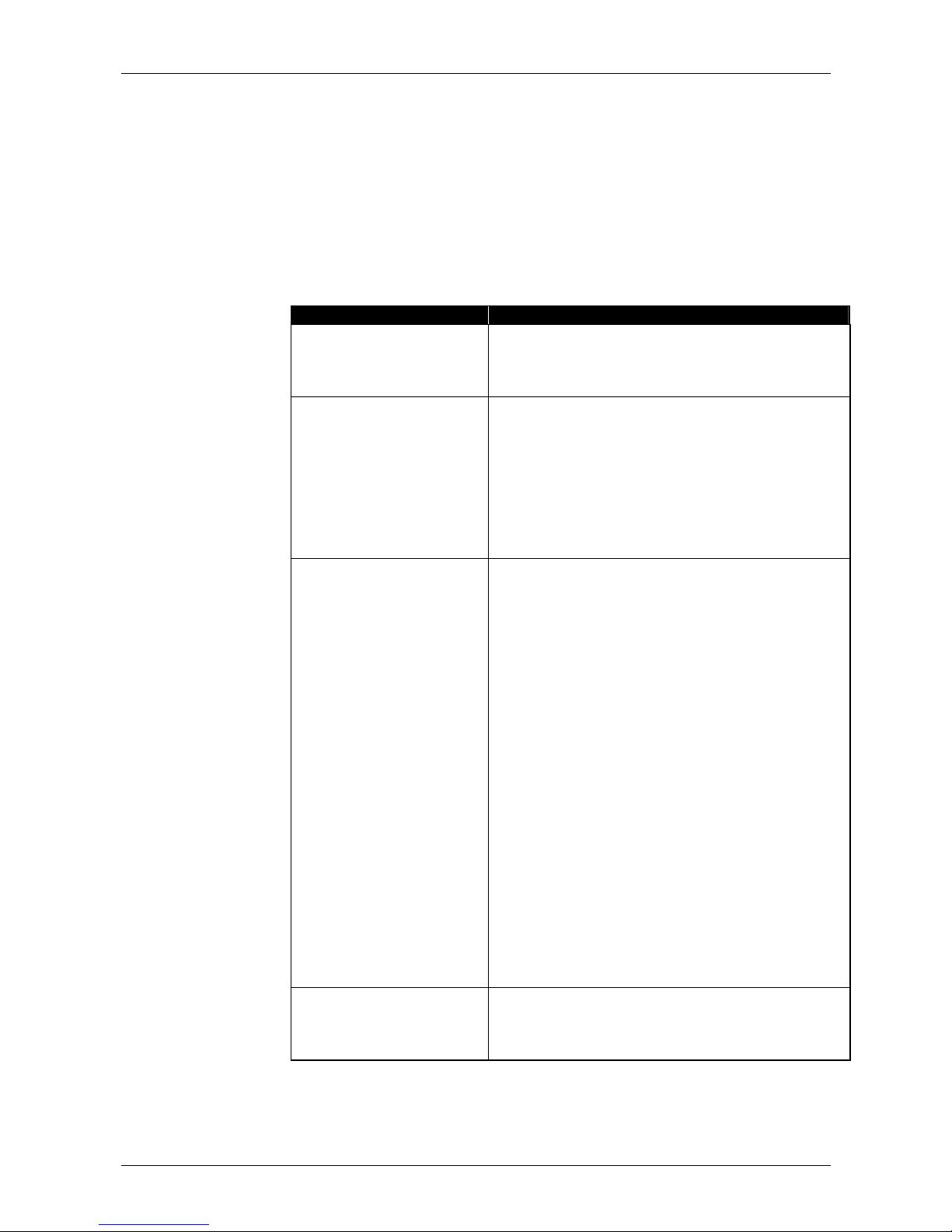
Parameter Group Parameters
Primary Motor Settings 1-A Motor Full Load Current
1-B Motor Maximum Start Time
1-C Motor Locked Rotor Current
1-D Motor Service Factor
Start/Stop Modes-1 2-A Start Mode
2-B Current Limit
2-C Current Ramp – Initial Start Current
2-D Current Ramp – Start Ramp Time
2-E Kickstart Current Level
2-F Kickstart Duration
2-G Excess Start Time
2-H Stop Mode
2-I Soft Stop Ramp Time
Protection Settings 3-A Undercurrent Level
3-B Undercurrent Trip Delay
3-C Instantaneous Overcurrent Level
3-D Instantaneous Overcurrent Trip Delay
3-E Current Imbalance Level
3-F Current Imbalance Trip Delay
3-G Phase Sequence
3-H Mains Frequency Trip Mode
3-I Mains Frequency Trip Range
3-J Mains Frequency Trip Delay
3-K Restart Delay
3-L Restart Temperature Check
3-M Auxiliary Trip A – Mode
3-N Auxiliary Trip A – Delay
3-O Auxiliary Trip A – Enable Delay
3-P Auxiliary Trip B – Mode
3-Q Auxiliary Trip B – Delay
3-R Auxiliary Trip B – Enable Delay
3-S Ground Fault Level
3-T Ground Fault Trip Delay
3-U Overvoltage Level
3-V Overvoltage Trip Delay
3-W Undervoltage Level
3-X Undervoltage Trip Delay
Inputs 4-A Local/Remote Control
4-B Serial Control – Remote Mode
4-C Input A Functionality
4-D Input B Functionality
Page 36
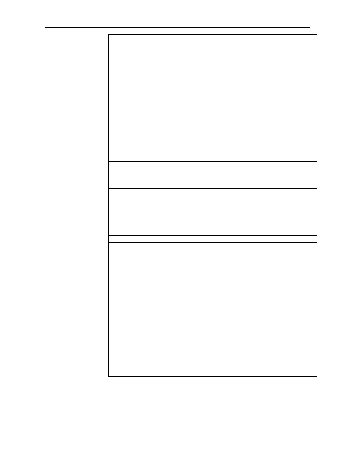
OPERATION: USER INTERFACE
MVS Series 35 710-03261-00D
Outputs 5-A Low Current Flag
5-B High Current Flag
5-C Motor Temperature Flag
5-D Output Relay A – Functionality
5-E Output Relay A – On Delay
5-F Output Relay A – Off Delay
5-G Output Relay B – Functionality
5-H Output Relay B – On Delay
5-I Output Relay B – Off Delay
5-J Output Relay C – Functionality
5-K Output Relay C – On Delay
5-L Output Relay C – Off Delay
5-M Analog Output A – Functionality
5-N Analog Output A – Range
5-O Analog Output A – Adjustment (maximum)
5-P Analog Output A – Adjustment (minimum)
5-Q Mains Reference Voltage
Auto-Stop 6-A Auto-Stop Mode
6-B Auto-Stop Time
Slip-Ring Motor Setup 9-A Primary Motor Ramp Configuration
9-B Secondary Motor Ramp Configuration
9-C Slip-Ring Rotor Resistance Contactor Time
9-D Slip-Ring Conduction Retardation
HMI Settings 11-A Language
11-B F1 Pushbutton Function
11-C F2 Pushbutton Function
11-D Programmable Screen – Top Left
11-E Programmable Screen – Top Right
11-F Programmable Screen – Bottom Left
11-G Programmable Screen – Bottom Right
Secondary Motor Settings 12-A Motor Full Load Current
Start/Stop Modes-2 13-A Start Mode
13-B Current Limit
13-C Current Ramp – Initial Start Current
13-D Current Ramp – Start Ramp Time
13-E Kickstart Current Level
13-F Kickstart Duration
13-G Excess Start Time
13-H Stop Mode
13-I Stop Ramp Time
Time-Overcurrent Protection 16-A Time-Overcurrent Level
16-B Time-Overcurrent Curve
16-C Time-Overcurrent Reset Time
16-D
Reserved
Restricted Parameters 20-A Security Access Code
20-B Parameter Lock
20-C Emergency Mode
20-D Motor Current Calibration
20-E Voltage Calibration
20-F Main Contactor Time
20-G Bypass Contactor Time
Page 37
OPERATION: USER INTERFACE
710-03261-00D 36 MVS Series
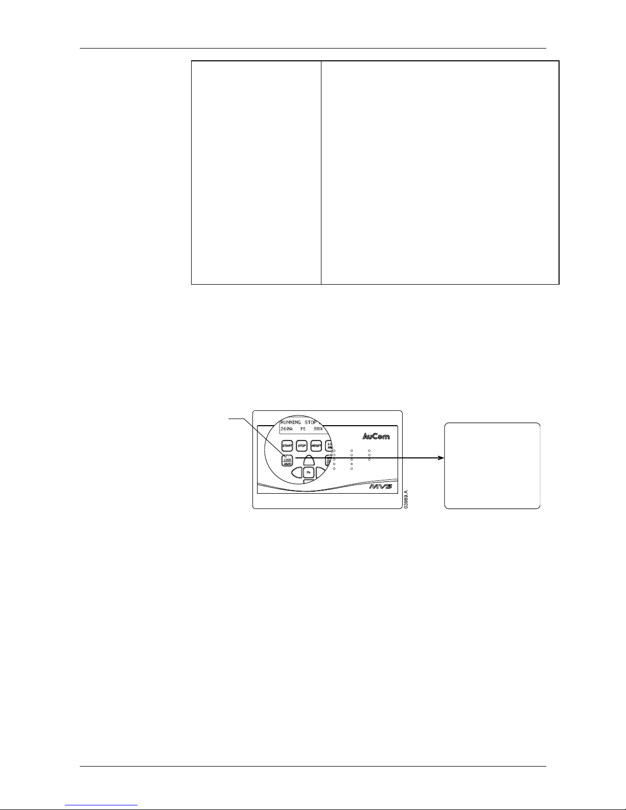
Protection Classes 21-A Overload
21-B Undercurrent
21-C Instantaneous Overcurrent
21-D Current Imbalance
21-E Mains Frequency
21-F Auxiliary Trip A
21-G Auxiliary Trip B
21-H Motor Thermistor
21-I Excess Start Time
21-J Starter Communications Timeout
21-K Battery/Clock Fail
21-L SCR Temperature Model
21-M Network Communications Timeout
21-N Ground Fault
21-O Overvoltage
21-P Undervoltage
21-Q
Reserved
21-R
Reserved
21-S Time-Overcurrent
You can access the Programming Menu at any time, including while the soft starter
is running. Any changes to the start profile take effect after the next start. All other
changes take effect immediately.
8.7 Logs Menu
The Logs Menu provides information on events, trips and performance.
To open the Logs Menu, press the <
LOGS> button while viewing the metering
screens.
Start
Stop
Reset
Input A
Input B
Start
Run
Trip
Warni ng
Remote
RLA
RLB
RLC
Series
START
LCL/
RMT
F1
LOGS
UNDO
STOP R ESET
F2
SETUP
TOOLS
STORE
Fn
Starter
Status
Control
Inputs
Relay
Outputs
Logs button
Logs Menu
Event Log
Trip Log
Performance Counters
Hours run (resettable)
Total elapsed time
Start counter (resettable)
Total starts
kWh counter (resettable)
Total kWh
Thermal model reset
To navigate through the Logs Menu:
• to open an individual log for viewing, press the ► button.
• to scroll through the entries in each log, press the ▲ and ▼ buttons. Individual
logs do not scroll around from the end to the beginning of the log.
• to return to the previous level, press the ◄ button.
• to close the Logs Menu, press the <LOGS> button.
Event Log
The event log stores time-stamped details of the starter's 99 most recent events
(actions, warnings and trips). Event 1 is the most recent and event 99 is the oldest
stored event.
To view items in the event log, press the ► button from the main event log screen.
Use the ▲ and ▼ buttons to navigate through the log and view events. To close
the log and return to the main display, press ◄.
Page 38
OPERATION: USER INTERFACE
MVS Series 37 710-03261-00D
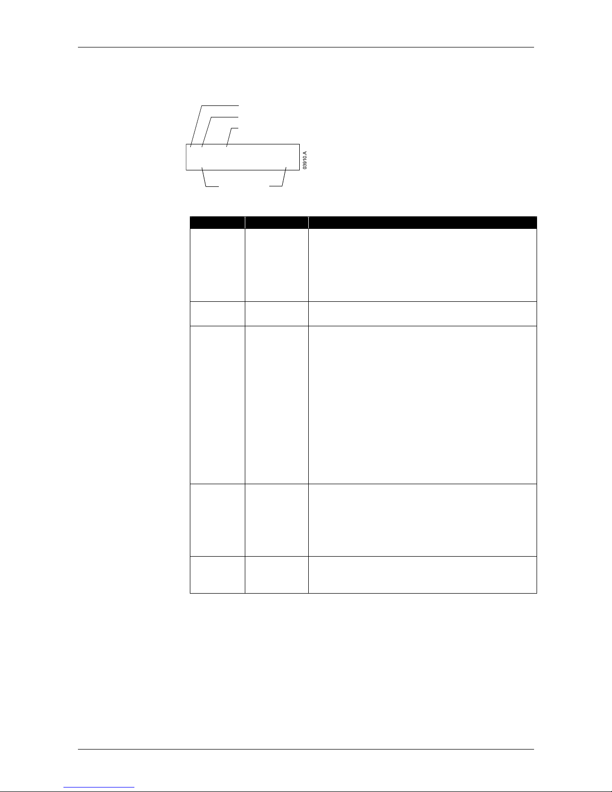
The event log stores a brief description of each event. When viewed, the top line
shows event number, description and type; the bottom line shows the date and
time stamp for the event.
1 OP LOAD SET 2
2004NOV25 14:22:34
Event number (1~99)
Event type code
Details
Date and time
Different details are recorded depending on the nature of the event.
Type Code Event Type Details
Protection
xxxxxxxxxxxxxxx y
xxxxxxxxxxxxxxx
= protection name
y = protection type
T – trip
W – warning
L – log only
CTRL PWR
Control Power
OFF – power removed
RESTORE – power restored
OP
Operation
Load Defaults = restore default settings
Load set 1 = load stored parameter set 1
Load set 2 = load stored parameter set 2
RESET Thermal = reset thermal model
RESET hrs run = reset hours run counter
RESET starts = reset starts counter
RESET kwh = reset kWh counter
Save set 1 = save user parameter set 1
Save set 2 = save user parameter set 2
SET Time = set date/ time clock
SIM protect = protection simulation
SIM run = run simulation
SIM signal = signalling simulation
PROG
Programming
xx-x y zzz
xx-x
= parameter number
y = number of adjacent parameters adjusted
zzz = command source
LCL – local pushbuttons
SRL – serial connection
RESET
Reset
LCL – reset via local pushbuttons
RMT – reset via remote inputs
SRL – reset via serial connection
Page 39
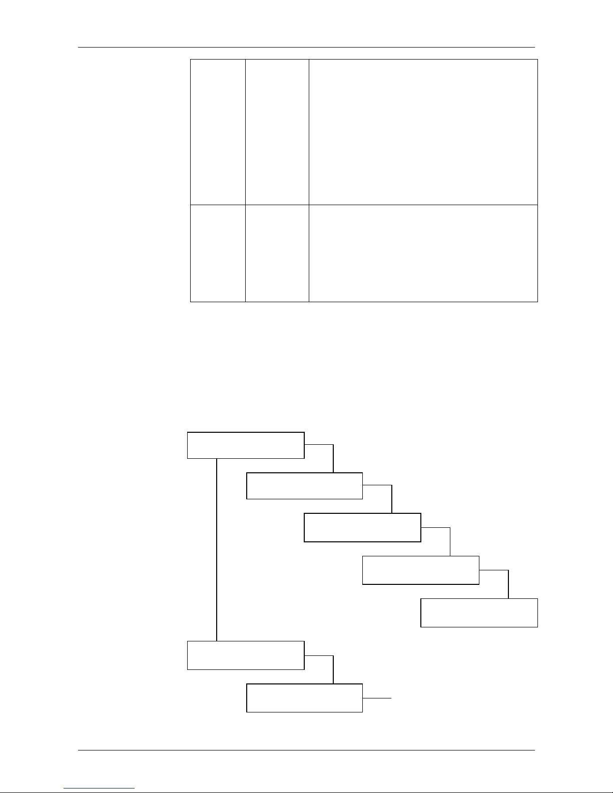
OPERATION: USER INTERFACE
710-03261-00D 38 MVS Series
START
Start
www xxx y z
www
= command source
LCL – local controller
RMT – remote inputs
SRL – serial connection
xxx = start time (seconds)
y = parameter set
1 = primary motor settings
2 = secondary motor settings
z = start type
N = normal
E = emergency
STOP
Stop
xxx yyy
xxx
= command source
LCL – local pushbuttons
RMT – remote inputs
SRL – serial connection
yyy = stop mode
CST – coast to stop
SFT – soft stop
Trip Log
When the MVS trips, details of the trip cause and starter state are recorded in the
trip log.
The trip log stores details of the eight most recent trip conditions. Trip 1 is the most
recent and trip 8 is the oldest stored trip. The MVS stores information about the
current and voltage on each phase when the trip occurred, and you can access
details about each phase by using the ◄ and ► buttons. To access details of the
next trip, use the ▲ and ▼ buttons. To close the log and return to the main
display, press ◄.
► Main screen: tri
p typ
e and time stamp.
1 Undercurrent T
2004MAR02 23:05:14
►
Mains Freq 50 Hz
State Running
Trip details: starter state and
mains frequency.
► Phase 1 details.
▼
Volts L1 4160
Amps L1 159
Phase 2 details. ►
Volts L1 4155
Amps L1 158
Phase 3 details.
Volts L1 4159
Amps L1 159
►
2 Overload Mtr 1 t
2004MAR02 22:03:27
...
Mains Freq 51 Hz
State Stopping
Page 40
OPERATION: USER INTERFACE
MVS Series 39 710-03261-00D
Performance Counters
The performance counters store details of the starter's lifetime operation.
To view the information in each counter, use the ▼ button to scroll through the list.
To reset a counter, press the ► button from the appropriate screen and press the
<
STORE> button to confirm the action.
►
Hours Run
9
87654.32
R
eset >
◄
Reset Hours Run?
O
K/store
▲
▼
Press <STORE> to reset or
<
UNDO> to cancel.
Total Elapsed Time
123456.78
▲
▼
►
Start Count
35
r
eset >
◄
Reset Start Counter?
O
K/Store
▲
▼
Press <STORE> to reset or
<
UNDO> to cancel.
Total Starts
45
▲
▼
►
kWh count
x
r
eset >
◄
Reset kWh Counter?
O
K/Store
▲
▼
Press <STORE> to reset or
<
UNDO> to cancel.
Total kWh
75923
▲
▼
Thermal Model Reset
Count = 2
Page 41
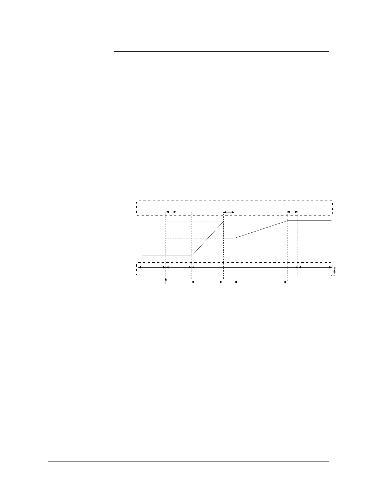
OPERATION: OPERATION
710-03261-00D 40 MVS Series
Operation
9
9.1 Using the MVS to Control a Motor
To soft start the motor, press the <START> button on the MVS Controller or
activate the Start remote input. The motor will start using the start mode selected
in parameter 2-A.
To soft stop the motor, press the <
STOP> button on the MVS Controller or activate
the Stop remote input. The motor will stop using the stop mode selected in
parameter 2-H.
To emergency stop the motor using the soft starter, one of the programmable
inputs (parameters 4-C and 4-D) must be configured for emergency stop. When
the input is activated, the soft starter will remove power from the motor and open
the main contactor. The motor will coast to stop.
To reset a trip on the soft starter, press the <
RESET> button on the MVS Controller
or open the Reset remote input.
9.2 Using the MVS to Control a Slip-Ring Motor
The MVS can be used to control a slip-ring motor, using rotor resistance.
RunningStarti ngPre-start testsReady
Star t
command
Bypass contactor
close time
Sub-states
Rotor resistance contactor
close time
High rotor resistance
current ramp retard
Low rotor resistance
current ramp retard
Main contactor
close time
Output voltage
100% voltage
Voltage at
conduction retard
States
In order to use the MVS with a slip-ring motor, set the following parameters:
• parameter 9-A or 9-B Primary or Secondary Motor Ramp Configuration must
be set to dual ramp
• an output relay (parameters 5-D to 5-J) must be set to rotor resistance. Wire
the relay to reduce the rotor resistance to provide suitable torque for the
application.
• parameter 9-C Slip-Ring Rotor Resistance Contactor Time defines the time
between the rotor resistance contactor closing and the start of the low
resistance current ramp. Set a time which is:
• long enough for the rotor resistance contactor to close
• short enough for the motor to retain speed
• parameter 9-D Slip-Ring Conduction Retard defines the level of conduction at
the start of the low resistance current ramp. Set a value which is:
• low enough to avoid a current pulse
• high enough for the motor to retain speed
Chapter 9
Page 42
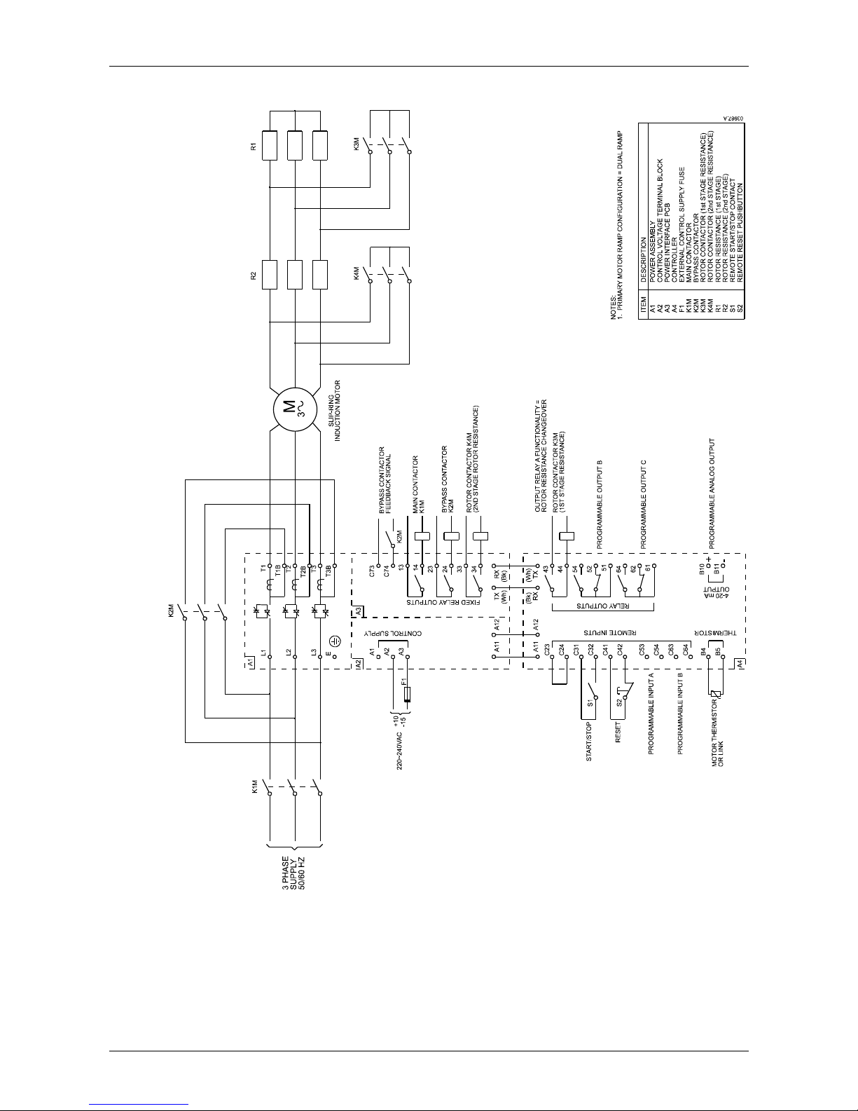
OPERATION: OPERATION
MVS Series 41 710-03261-00D
Diagram 5: Slip-Ring Motor Connection
Page 43
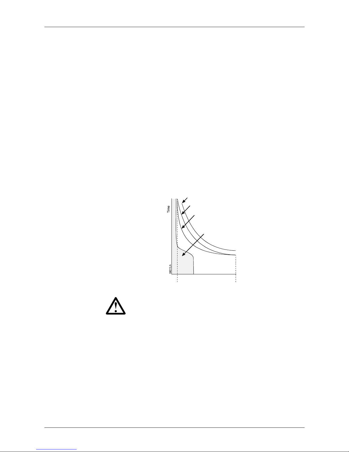
OPERATION: OPERATION
710-03261-00D 42 MVS Series
9.3 Motor, System and Soft Starter Protection Mechanisms
The MVS incorporates extensive protection features to ensure safe operation of the
motor, system and soft starter. Most protection features can be customised to suit
the installation. Use parameter group 3 to control the situation where the
protections will activate and parameter group 21 to select the soft starter's
response. The default response is to trip the soft starter.
9.4 Motor Overload Protection
The MVS offers two forms of motor overload protection:
• a motor thermal model that monitors the performance of the motor and
calculates its status at all times. This protection is based on the motor
information programmed in parameter group 1, and the thermal model adjusts
itself according to the motor's recent operating history (including temperature
rise from previous operation). This model provides finer motor protection than
the time-overcurrent model, if the programmed motor information is accurate.
• a time-overcurrent model that calculates the motor's status according to a
predefined performance curve. This method is based on IEEE standard
C37.112-1996 (
Inverse-Time Characteristic Equations for Overcurrent Relays)
and provides similar protection to a relay. This model may suit users familiar
with time-overcurrent protection models, but provides coarse motor protection.
The two methods offer similar kinds of protection and we recommend using only
one of the two methods.
Motor current
Motor failure curve
Motor thermal model
protection curve
Motor
service factor
Locked rotor
current
Time-overcurrent
protection curve
Typi cal moto r
operating curre nt
NOTE
The soft starter can only be protected from short circuits by suitably
selected R Rated fuses.
Page 44
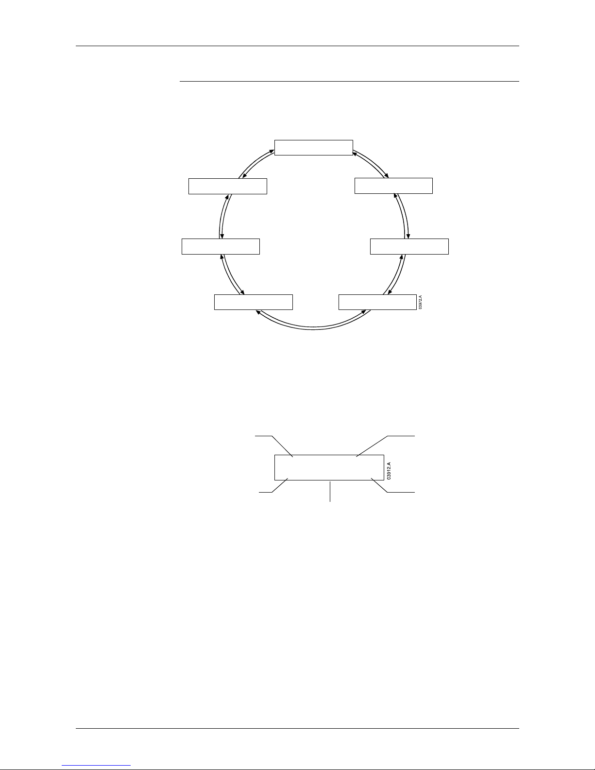
OPERATION: OPERATING FEEDBACK
MVS Series 43 710-03261-00D
Operating Feedback
10
10.1 Metering Screens
The MVS uses metering screens to display information on the soft starter's
performance. Use the ▲ and ▼ buttons to move between metering screens.
RUNNING STOP IN 14:02
260A M1 * 100%
L1 260 A L2 258 A
L3 261 A GC 260 A
6600 V 6 610 V 6605 V
260 A 258 A 261 A
2515 KW 3372 HP
2970 KVA 0.9 2 PF
LAST START 12 S
400% FLC T-RISE 40%
DATE/TIME
2004NOV2 8 11:20: 36
STARTING 1040 A
11540 1080
Last start
information
Date/time
Programmable
screen
Starter status
Current
Voltage and current
Power metering
Pressing the ► button while viewing the Date/Time screen lets the user set the
date and time on the MVS Controller. Pressing the ► button at any other screen
opens the Programming Menu.
10.2 Starter Status
The starter status screen shows real-time details of the starter's status, including
current and temperature:
Running Stop in 14:02
260A M1 88%
Stat us
Auto-stop information
Parameter set
Motor temperature
Motor current
The information on the screen is arranged as follows:
• top left: status information (Ready, Starting, Running, Stopping or Tripped).
• top right: auto-stop information.
• bottom left: motor current (mean average of three phases).
• bottom centre: parameter set currently in use (primary (M1) or secondary
(M2)).
• bottom right: motor temperature (based on the thermal model).
When the motor temperature approaches the trip level, the temperature will flash.
When the motor's thermal capacity will not permit a restart, an asterisk appears in
front of the temperature.
When a warning occurs, the top line of the status screen alternates with the
warning type. The lower line continues to display current and temperature
information:
Chapter 10
Page 45
OPERATION: OPERATING FEEDBACK
710-03261-00D 44 MVS Series
Current Imbalance
260 A M1 88%
RUNNING stop in 14:02
260 A M1 88%
When a trip occurs, the status screen is replaced by details of the trip type:
Tripped
Current Imbalance
When operating in Emergency Mode, the screen shows "Emergency Operation":
Emergency Operation
260 A M1 88%
10.3 Current
The current screen shows real-time details of the ground current and the line
current on each phase:
L1 260A L2 258A
L3 261A GC 1A
When current is not being measured, the display will show 0.
10.4 Voltage and Current
The voltage and current screen shows real-time line voltage and line current on
each phase:
6600V 6610V 6605V
260A 258A 261A
L1 L2 L3
When the motor is not running, the display will show ---- in place of voltage and
0 A current.
10.5 Power Metering
The power metering screen shows details of total motor power, motor
horsepower, motor active power and power factor.
2515 kW 3372 hp
2970 kVA 0.92 pf
10.6 Last Start Information
The last start information screen shows details of the most recent successful
start:
• start duration (seconds)
• maximum start current drawn (as a percentage of motor full load current)
• calculated rise in motor temperature
Last start 12 Sec
400 % 40% T-ri se
If data is not available from the last start, the display will show 0 for each field.
10.7 Date/Time
The date/time screen shows the current system date and time (24 hour format):
Date/Time
2004Nov22 11:20:36
To adjust the current date and time, press the ► button while viewing the
Date/Time metering screen. Use the ◄ and ► buttons to select which part of the
date or time to edit, and use the ▲ and ▼ buttons to change the value.
Page 46

OPERATION: OPERATING FEEDBACK
MVS Series 45 710-03261-00D
Pressing <STORE> from the seconds element stores the current value and returns
to the metering screens. To return to the metering screens without saving
changes, press the ◄ button repeatedly.
10.8 Programmable Screen
The programmable screen shows the information selected in parameters 11-D to
11-G.
Starting 1040A
11540 1080
The default settings are starter state, motor current, kWh and hours run.
Page 47
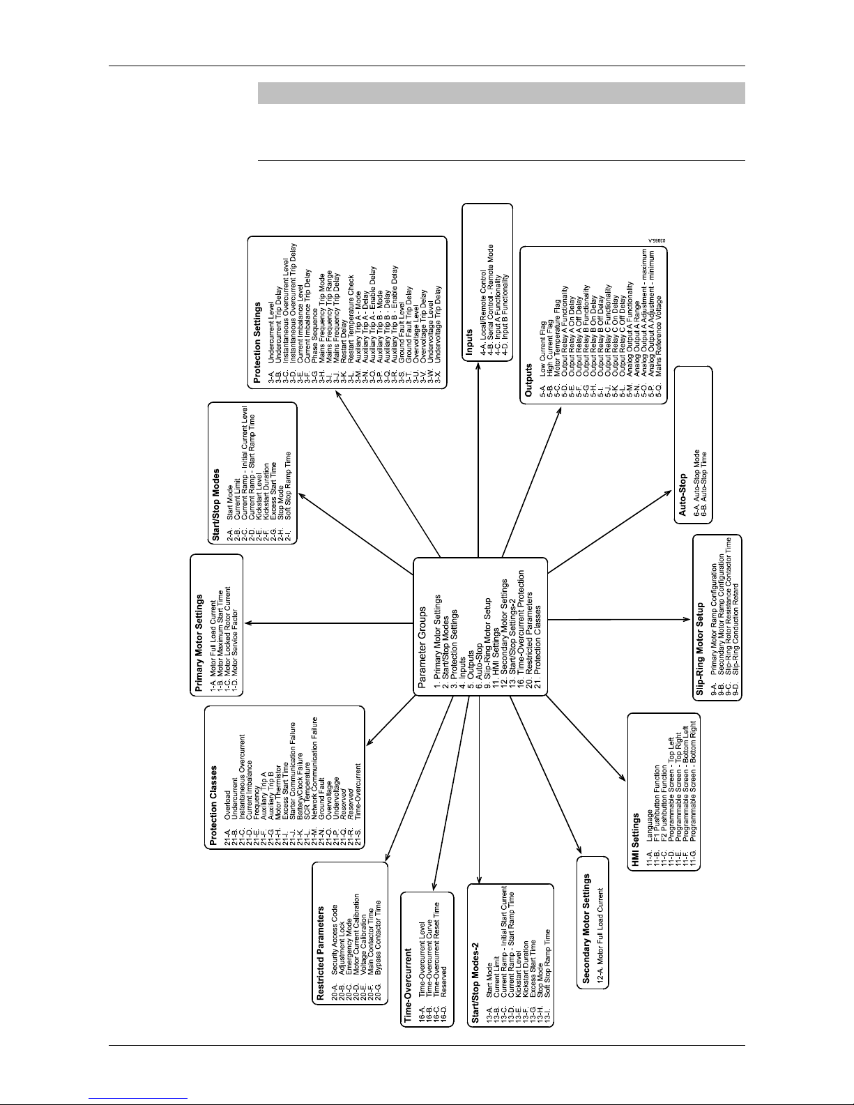
APPENDIX: MENU MAPS
710-03261-00D 46 MVS Series
Appendix
Menu Maps
11
11.1 Programming Menu
Section 4
Chapter 11
Page 48
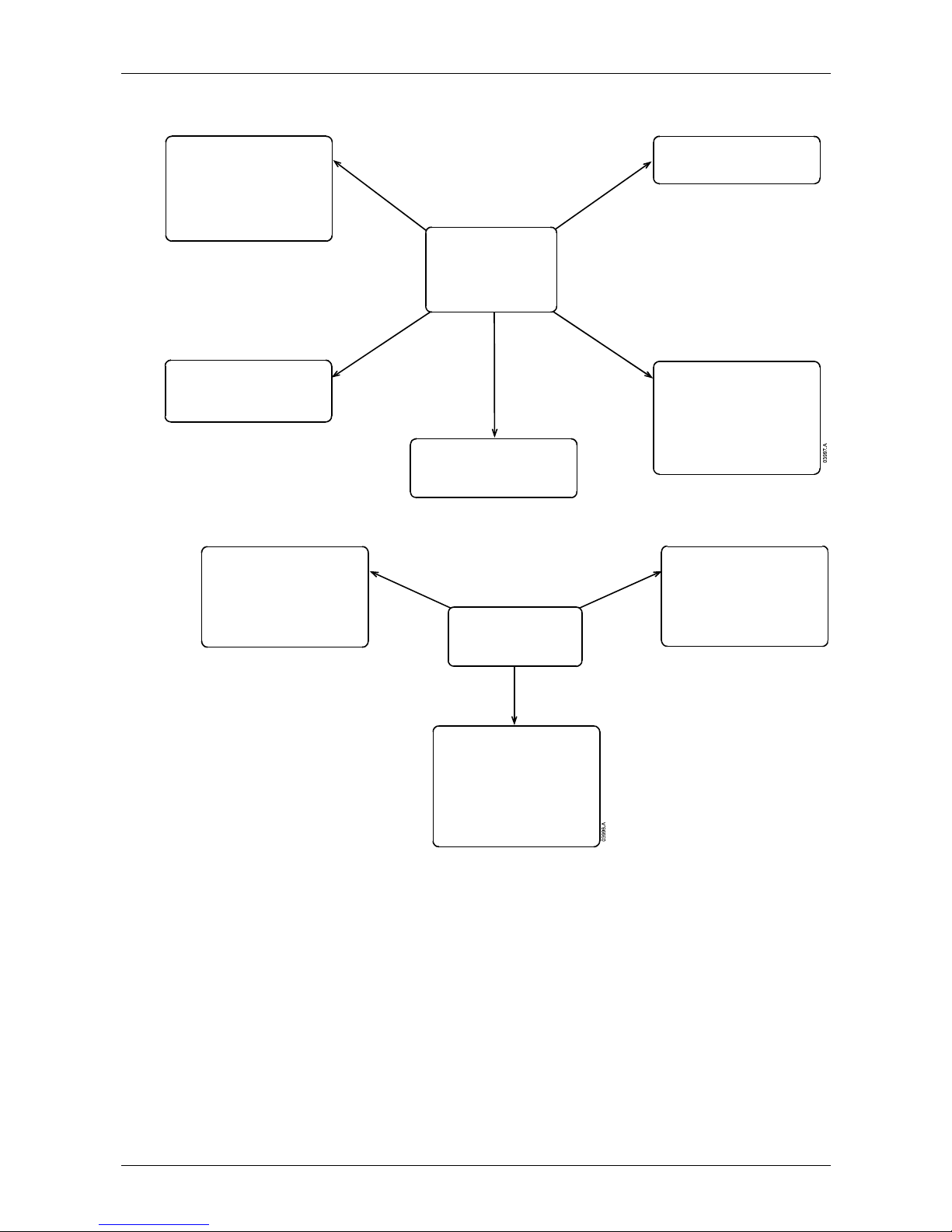
APPENDIX: MENU MAPS
MVS Series 47 710-03261-00D
11.2 Commissioning Menu
Output Signal Simulation
Simulate outp ut signalling to confirm
operation of the outputs.
Analog output
Low current flag
High current flag
Relay A
Relay B
Relay C
Parameter Archive
Save the current programmed settings,
reload a previously saved group of
settings, or reset the soft starter to the
factory defau lt values.
Load defau lts
Load user set 1
Load user set 2
Save user set 1
Save user set 2
Run Simulation
Simulate operation of the soft starter
without a motor connected, to test the
control circuits and associated
components.
Protection Simulation
Simulate trip conditions to confirm the
soft starter responds appropriately (by
tripping, w arning or writ ing to log) .
Reset Thermal Models
Reset the so ft starter thermal model if
required in emergencies.
Commissioning Menu
Reset Thermal Models
Parameter Archive
Run Simulation
Protection Simulation
Output Signal Simulation
11.3 Logs Menu
Event Log
Stores key information about the last 99
events involving the soft starter:
Configuration changes
Starts, stops and resets
Trips
Warnings
Logged protection events
Performance Counters
Stores details of the soft starter's operation
and performance:
Hours run since counter was last rese t
Lifetim e hours run
Starts since counter was last reset
Lifetime starts
kWh since counter was last reset
Lifetime kWh
Number of times thermal model has
been re set
Tri p L og
Stores complete details of the last eight
trips:
Protection type
Date and time
Soft starter stat e
Mains frequency
Current and voltage on each phase
Logs Menu
Event Log
Trip Log
Performance Counters
Page 49
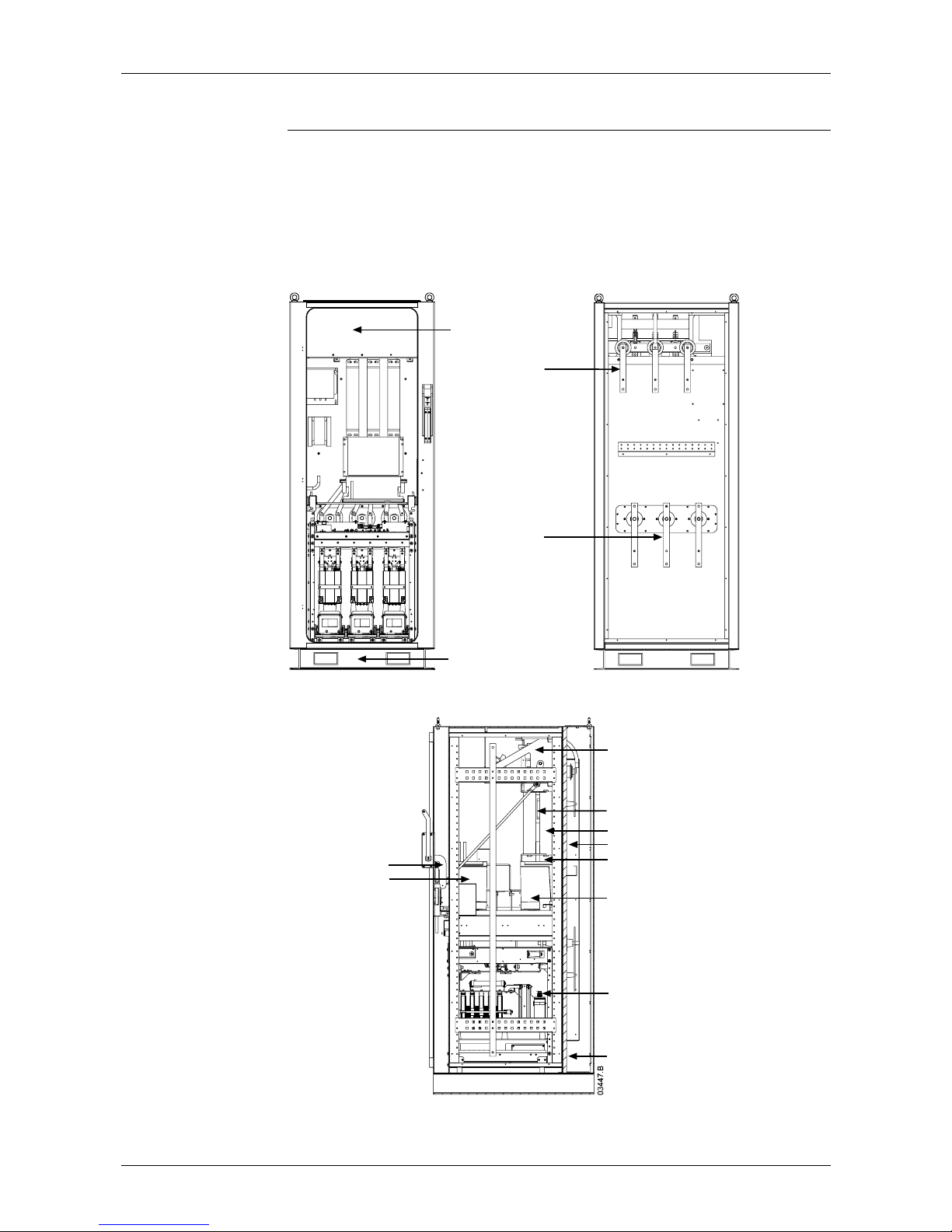
APPENDIX: AUCOM ENCLOSURES
710-03261-00D 48 MVS Series
AuCom Enclosures
12
MVS soft starters are optionally available in enclosed formats, with a wide range of
installation configurations. Enclosures are available in IP32 and IP54 ratings (other
ratings are available by negotiation).
Power input and output can be top or bottom entry and power input can be
provided from either cables or top horizontal bus bars. The diagrams below
illustrate one possible configuration for installation.
Front View
Welded steel plinth
Earth switch viewing window
Rear View
Line bus bars
Motor bus bars
Side View
Interlock mechanism
Fuses
Main contactor
Rear cabling cavity
Power assembly
Bypass contactor
Low voltage trunking
Control voltage transformer
Metering/ protection transformer
Main isolator/ earth switch
Chapter 12
Page 50
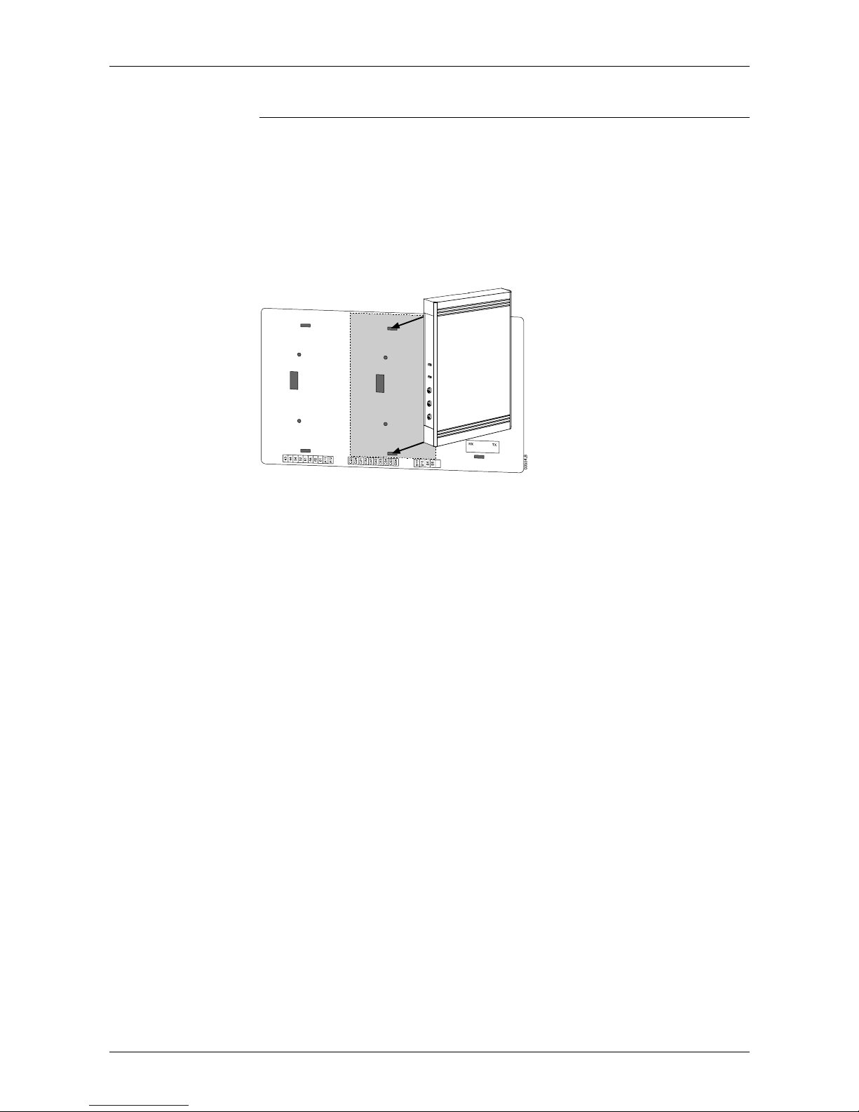
APPENDIX: ACCESSORIES
MVS Series 49 710-03261-00D
Accessories
13
MVS Series soft starters are compatible with a range of accessories, allowing easy
integration into a control network.
13.1 Communication Interfaces
MVS Series soft starters support network communication using the Profibus,
DeviceNet and Modbus RTU protocols, via an easy-to-install communication
interface.
Communication interfaces attach to the back of the MVS Controller:
Modbus Interface
Part Number: PIM-MB-01
The Modbus Interface enables control and monitoring via a Modbus RTU network.
Refer to the Modbus Interface Instructions for further details.
Profibus Interface
Part Number: PIM-PB-01
The Profibus Interface enables control and monitoring via a Profibus network.
Refer to the Profibus Interface Instructions for further details.
DeviceNet Interface
Part Number: PIM-DN-01
The DeviceNet Interface enables control and monitoring via a DeviceNet network.
Refer to the DeviceNet Interface Instructions for further details.
Chapter 13
Page 51
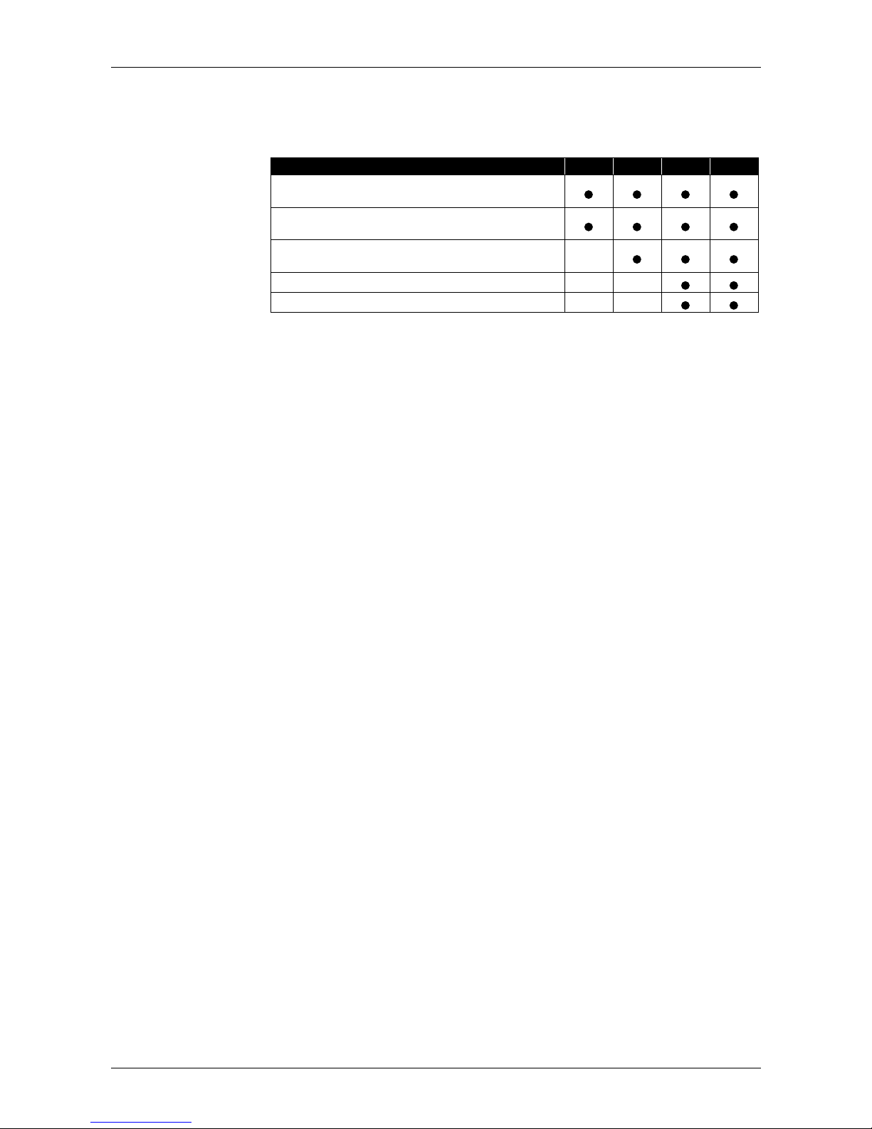
APPENDIX: ACCESSORIES
710-03261-00D 50 MVS Series
13.2 PC Software
WinMaster is a purpose-designed software suite for control and monitoring of up to
99 soft starters. WinMaster is compatible with all AuCom soft starter ranges.
Feature CSX CSXi IMS2 MVS
Operational Control
(Start, Stop, Reset, Quick Stop)
Starter Status Monitoring
(Ready, Starting, Running, Stopping, Tripped)
Performance Monitoring
(
Motor Current, Motor Temperature
)
Upload Parameter Settings
Download Parameter Settings
To use WinMaster with the MVS, the soft starter must be fitted with a Modbus
Interface (PIM-MB-01).
Refer to the WinMaster User Manual for further details.
Page 52

NOTES
MVS Series 51 710-03261-00D
Page 53

NOTES
710-03261-00D 52 MVS Series
 Loading...