

Page 1
SERVICE MANUAL
Page 2

CONTENTS
710-02696-00C CSX Series Page 1
Section 1 Caution Statements ................................................................................................................................................................2
1.1 Safety Regulations........................................................................................................................................................................................................2
Section 2 Troubleshooting........................................................................................................................................................................3
2.1 Functional Tests ............................................................................................................................................................................................................ 3
2.2 Fault Diagnosis...............................................................................................................................................................................................................4
Section 3 Avoiding Damage.....................................................................................................................................................................7
3.1 SCRs.................................................................................................................................................................................................................................... 7
3.2 Output Relays................................................................................................................................................................................................................ 7
3.3 Control Inputs................................................................................................................................................................................................................ 8
Section 4 Service Instructions..................................................................................................................................................................9
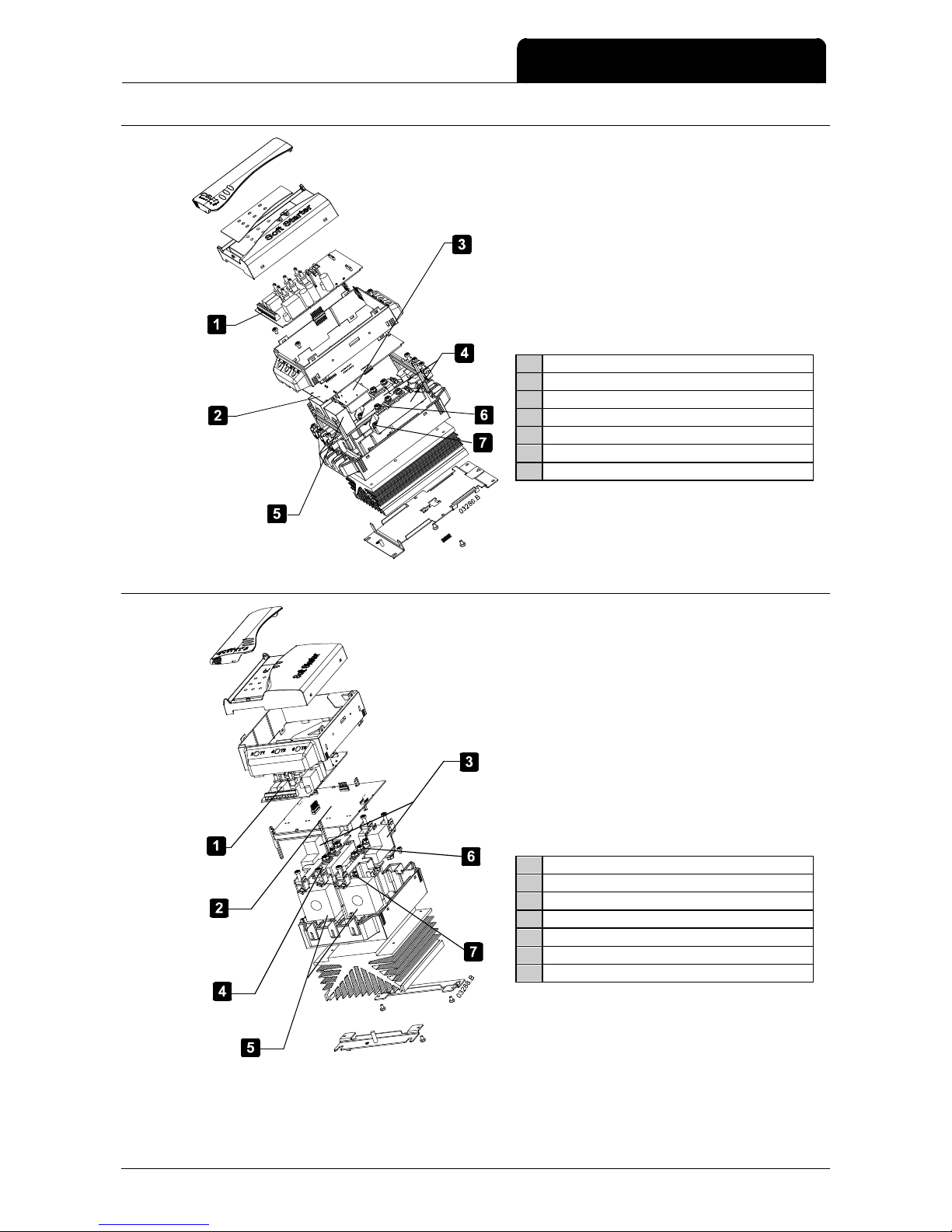
4.1 Exploded View CSX-007~CSX-030................................................................................................................................................................ 9
4.2 Exploded View CSX-037~CSX-055................................................................................................................................................................ 9
4.3 Exploded View CSX-075~CSX-110............................................................................................................................................................. 10
4.4 Exploded View CSXi-007~CSXi-030........................................................................................................................................................... 11
4.5 Exploded View CSXi-037~CSXi-055........................................................................................................................................................... 11
4.6 Exploded View CSXi-075~CSXi-110........................................................................................................................................................... 12
Section 5 Spare Parts................................................................................................................................................................................13
5.1 CSX................................................................................................................................................................................................................................... 13
5.2 CSXi ................................................................................................................................................................................................................................. 15
5.3 Finding the Batch Number .................................................................................................................................................................................. 17
5.4 SCR Connections ..................................................................................................................................................................................................... 17
Section 6 Disposal Instructions............................................................................................................................................................19
Contents
Page 3

CAUTION STATEMENTS
Page 2 CSX Series 710-02696-00C
WARNING - ELECTRICAL SHOCK HAZARD
CSX Series soft starters contain dangerous voltages when connected to mains voltage. Only a competent
electrician should carry out the elec
t
rical installation. Improper installation of the motor or the soft starter may
cause equipment failure, serious injury or death. Follow this manual and local electrical safety codes.
1.1 Safety Regulations
Disconnect the soft starter from mains voltage before carrying out repair work.
Stopping the soft starter does not disconnect the equipment from mains voltage and leaves one phase connected to
the motor. The soft starter should not be used as a safety switch.
NOTE
It is the responsibility of the user or person installing the soft starter to provide proper grounding and branch
circuit protection according to local electrical safety codes.
NOTE
Many electronic components are sensitive to static electricity. Voltages so low that they cannot be felt,
seen or heard, can reduce the life, affect performance, or completely destroy sensitive electronic
components. When performing service, proper ESD equipment should be used to prevent possible
damage from occurring.
NOTE
The CSX Series soft starter is not user serviceable. The unit should only be serviced by authorised service
personnel. Unauthorised tampering with the unit will void the product warranty.
Section 1 Caution Statements
© 2003-2008 AuCom Electronics Ltd. All Rights Reserved.
As AuCom is continuously improving its products it reserves the right to modify or change the specification of its products at
any time without notice. The text, diagrams, images and any other literary or artistic works appearing in this document are
protected by copyright. Users may copy some of the material for their personal reference but may not copy or use material
for any other purpose without the prior consent of AuCom Electronics Ltd. AuCom endeavours to ensure that the
information contained in this document including images is correct but does not accept any liability for error, omission or
differences with the finished product.
Page 4

TROUBLESHOOTING
710-02696-00C CSX Series Page 3
2.1 Functional Tests
Use the tests in this section to identify the cause of problems with the soft starter.
Basic Functionality Test
This procedure tests that the soft starter is receiving control voltage.
1. Remove all external wiring from the soft starter control inputs (01, 02).
2. Connect the soft starter to control voltage (A1-A2 or A2-A3).
• The Ready LED should come on. If it does not, the Main Control PCB is damaged.
Power Circuit Test
This procedure tests the soft starter's power circuit, including the SCRs, Interface PCB and Main Control PCB.
1. Disconnect the soft starter from mains voltage (L1, L2, L3), control voltage (A1, A2, A3) and from the motor (T1,
T2, T3).
2. Use a 500 VDC insulation tester to measure the resistance across L1-T1, L3-T3, T1-L1 and T3-L3. The resistance
should be between 30 kΩ and 500 kΩ and equal for all measurements.
• If the resistance is below 30 kΩ for any measurement, the SCR or bypass relay on that phase has been
damaged and must be replaced.
• If the resistance is above 500 kΩ for any measurement, the Main Control PCB or Interface PCB may be
faulty or there may be a faulty connection between these two PCBs. To isolate the fault, perform the
PCB integrity test.
CSX Start Performance Test
This procedure tests that the CSX soft starts correctly.
1. Connect the CSX to mains voltage and to a motor.
2. Measure the voltage across L1-T1 and L3-T3. This should be close to the nominal mains voltage.
• If the voltage is zero, the SCR or bypass relay on that phase may have failed.
3. Command the CSX to start. While the CSX is starting, measure the voltage across L1-T1 and L3-T3. The voltage
should fall to less than 2 VAC just before the CSX reaches Run mode.
• If the voltage remains near nominal mains voltage, the SCR is not firing correctly. This can be caused by
a faulty Main Control PCB, a faulty Interface PCB, or a poor connection between these two PCBs. To
isolate the fault, perform the PCB integrity test.
CSXi Start Performance Test
This procedure tests that the CSXi soft starts correctly.
1. Calculate the expected motor start current by multiplying the CSX
i
current rating by the Motor FLC setting and
the Current Limit
setting.
2. Connect the CSX
i
to mains voltage and to a motor.
3. Command the CSX
i
to start. While the CSXi is starting, measure the current on L1 and L3.
• If the current does not stabilise at expected level, the SCR is not firing correctly. This can be caused by a
faulty Main Control PCB, a faulty Interface PCB, or a poor connection between these two PCBs. To
isolate the fault, perform the PCB integrity test.
Bypass Relay Test
CSX Series soft starters incorporate internal bypass relays. This procedure tests the operation of the internal bypass
relays.
1. Connect the soft starter to mains voltage and to a motor.
2. Measure the voltage across L1-T1 and L3-T3. This should be close to the nominal mains voltage.
• If the voltage is zero, the SCR or bypass relay on that phase may have failed.
3. Command the soft starter to start. When the Run LED stops flashing you should hear the bypass relay close.
Section 2 Troubleshooting
Page 5

TROUBLESHOOTING
Page 4 CSX Series 710-02696-00C
• If the bypass relay does not close, the bypass relay, Main Control PCB or Interface PCB may be faulty, or
there may be a faulty connection between these components. To isolate the fault, perform the bypass
relay integrity test.
4. When the soft starter is running, measure the voltage across L1-T1 and L3-T3. This should be less than 0.5 VAC.
• If the voltage remains near nominal mains voltage, the bypass relay did not close. This can be caused by
a faulty relay, faulty Main Control PCB, a faulty Interface PCB, or a poor connection between these two
PCBs. To isolate the fault, perform the bypass relay integrity test.
5. Command the soft starter to stop. You should hear the bypass relay open.
• If the bypass relay does not open, perform the bypass relay integrity test.
2.2 Fault Diagnosis
PCB Integrity Test
This procedure further isolates a fault with the soft starter's control circuitry.
1. Verify that the connection between the Main Control PCB and the Interface PCB is sound.
• remove and refit the Main Control PCB
• check whether the soft starter now operates correctly
2. Verify that the Main Control PCB is sound
• remove and replace the Main Control PCB
• check whether the soft starter now operates correctly
3. Verify that the Interface PCB is sound
• refit the original Main Control PCB
• remove and replace the Interface PCB
• check whether the soft starter now operates correctly
If the fault cannot be traced to either the Main Control PCB or the Interface PCB, replace both PCBs.
Bypass Relay Integrity Test
This procedure further isolates a fault with the soft starter's bypass circuitry.
1. Verify that the connections between the Main Control PCB and the Interface PCB, and between the Interface
PCB and the bypass relay are sound.
• remove the Main Control PCB
• remove the Interface PCB
• refit the Interface PCB to the bypass relays
• refit the Main Control PCB
• check whether the soft starter now operates correctly
2. Verify that the bypass relay is sound
• remove the Main Control PCB and Interface PCB
• momentarily apply 24 VDC to the bypass relay control pins. The bypass relay should change state. The
bypass relays are latching, so behaviour must be checked by applying voltage in both directions.
If the bypass relay does not change state correctly, it must be replaced.
Figure 1: Bypass relay control pins (7 kW ~ 30 kW models)
Page 6

TROUBLESHOOTING
710-02696-00C CSX Series Page 5
Figure 2: Bypass relay control pins (37 kW ~ 55 kW models)
Figure 3: Bypass relay control wires (75 kW ~ 110 kW models)
PCB Visual Inspection
Damage to the MOV on the Main Control PCB may indicate that incorrect control voltage has been applied to the
unit.
Figure 4: Location of MOV on Main Control PCB
Damage to the MOVs and/or surrounding circuitry on the Interface PCB may indicate that the soft starter has suffered
overvoltage. This usually also damages the SCRs.
Page 7

TROUBLESHOOTING
Page 6 CSX Series 710-02696-00C
Figure 5: MOV location on Interface PCB (7 kW ~ 30 kW models)
Figure 6: MOV location on Interface PCB (37 kW ~ 55 kW models)
Figure 7: MOV location on Interface PCB (75 kW ~ 110 kW models)
Page 8

AVOIDING DAMAGE
710-02696-00C CSX Series Page 7
3.1 SCRs
SCR damage is generally caused by overcurrent, overvoltage or overtemperature. To prevent future damage, check
that the soft starter has been installed properly. Common causes of SCR problems include:
Overcurrent:
• cable fault on soft starter output
• motor fault
• start current and/or start time exceeds the soft starter's rating
• starts per hour exceed the soft starter rating
Overvoltage:
• power supply transient or surge
• lightning strike (direct or indirect) on power supply
• motor fault
• loose connection in power circuit, before or after the starter
• power factor correction connected to the output of the soft starter
• over-corrected bulk power factor correction on a lightly loaded system causing severe ringing voltages
Overtemperature:
• blocked heatsinks or restricted ventilation
• inadequate ventilation
• excessive ambient temperatures
• bypass relay fails to close during running
Protecting SCRs
Modern SCRs are generally rugged and reliable. However, the risk of SCR damage can be reduced by using
semiconductor fuses and/or a main contactor.
• Semiconductor Fuses
Semiconductor fuses reduce the potential for SCR damage caused by short circuits on the output of the starter.
Protection systems such as circuit breakers or HRC fuses do not operate quickly enough to protect SCRs from short
circuits.
• Main Contactors
SCRs are most vulnerable to overvoltage damage when voltage is applied to their input terminal while they are off. In
this condition the SCR is blocking the full line voltage. Using a main contactor to remove voltage from the SCR input
when the starter is off eliminates the risk of SCR damage due to overvoltage.
3.2 Output Relays
CSX Series soft starters have one fixed output relay (terminals 13, 14) and CSXi soft starters have one fixed and one
programmable output relay (terminals 13, 14 and 23, 24). These relays are often used to control the main contactor.
The electronic contactor coils used in many contactors have a high initial inrush current, which can damage the soft
starter's internal relays if the contactor coil is switched directly.
Using the Soft Starter to Switch a Contactor
Before using the soft starter's output relay to switch an electronic contactor coil, consult the contactor manufacturer.
Some contactor manufacturers (eg Klockner-Moeller) state that you cannot use PCB mount relays for direct switching
of their electronic contactor coils.
If this is the case, there are two solutions:
1. Use the soft starter's output relay to control a slave relay. This slave relay can then be used to directly switch the
electronic contactor coil circuit.
Section 3 Avoiding Damage
Page 9

AVOIDING DAMAGE
Page 8 CSX Series 710-02696-00C
1 Soft starter output relay
2 Slave relay coil
3 Contactor coil
2. If the contactor has a volt free electronic input (low voltage/low current), the soft starter's output relay can be
wired directly into this input for contactor control.
1 Soft starter output relay
2 Contactor coil
3.3 Control Inputs
CSX Series soft starters can be operated by external two wire or three wire control signals. External switches are
configured and wired into control input terminals 01, 02.
• External switches operating the control inputs must be rated for the control voltage being used and a
continuous current of 100 mA.
• Incorrect configuration and wiring of the external contacts/switches to the control input terminals may cause
damage.
• If long cable runs are used, wiring must be twisted pair or shielded cable and must be separated from AC
power cables by at least 300 mm.
NOTE
Applying voltage to the control inputs will damage the soft starter. Damage to the control inputs is not
covered by warranty.
Page 10

SERVICE INSTRUCTIONS
710-02696-00C CSX Series Page 9
4.1 Exploded View CSX-007~CSX-030
1 Main Control PCB
2 Interface PCB
3 Bypass relays
4 SCRs
5 SCR-bus bar connection (tighten to 4 Nm)
6 SCR-heatsink connection (tighten to 4 Nm)
4.2 Exploded View CSX-037~CSX-055
1 Main Control PCB
2 Interface PCB
3 Bypass relays
4 SCRs
5 SCR-bus bar connection (tighten to 5 Nm)
6 SCR-heatsink connection (tighten to 4 Nm)
Section 4 Service Instructions
Page 11

SERVICE INSTRUCTIONS
Page 10 CSX Series 710-02696-00C
4.3 Exploded View CSX-075~CSX-110
1 Main Control PCB
2 Interface PCB
3 Bypass relays
4 SCRs
5 SCR-bus bar connection (tighten to 9 Nm)
6 SCR-heatsink connection (tighten to 4 Nm)
Page 12
SERVICE INSTRUCTIONS
710-02696-00C CSX Series Page 11
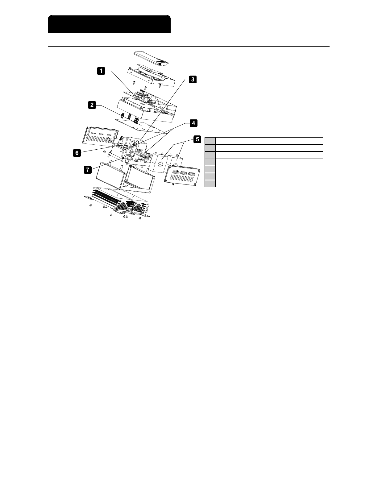
4.4 Exploded View CSXi-007~CSXi-030
1 Main Control PCB
2 Interface PCB
3 Bypass relays
4 SCRs
5 Current transformers
6 SCR-bus bar connection (tighten to 4 Nm)
7 SCR-heatsink connection (tighten to 4 Nm)
4.5 Exploded View CSXi-037~CSXi-055
1 Main Control PCB
2 Interface PCB
3 Bypass relays
4 SCRs
5 Current transformers
6 SCR-bus bar connection (tighten to 7 Nm)
7 SCR-heatsink connection (tighten to 4 Nm)
Page 13
SERVICE INSTRUCTIONS
Page 12 CSX Series 710-02696-00C
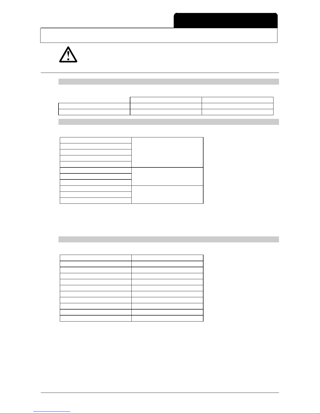
4.6 Exploded View CSXi-075~CSXi-110
1 Main Control PCB
2 Interface PCB
3 Bypass relays
4 SCRs
5 Current transformers
6 SCR-bus bar connection (tighten to 12 Nm)
7 SCR-heatsink connection (tighten to 4 Nm)
Page 14
SPARE PARTS
710-02696-00C CSX Series Page 13
NOTE
The numbers shown indicate the quantity required for each starter. Unless otherwise indicated, spare
part kits contain only one of each item.
5.1 CSX
Main Control PCB
Each soft starter requires one Main Control PCB.
C1 Models C2 Models
CSX-xxx-V4-xx 995-02535-00 995-02536-00
CSX-xxx-V6-xx 995-02539-00 995-02540-00
CSX Interface PCB
Each soft starter requires one Interface PCB.
CSX-007
CSX-015
CSX-018 995-02543-00
CSX-022
CSX-030
CSX-037
CSX-045 995-04516-00
1
CSX-055
CSX-075
CSX-090 995-03874-00
2
CSX-110
1
This part is suitable for use with CSX Series units of version 10 or later (serial number xxxxx-10). Please contact
AuCom for assistance with earlier versions.
2
This part is suitable for use with CSX Series units of version 7 or later (serial number xxxxx-07). Please contact
AuCom for assistance with earlier versions.
SCRs
Each soft starter requires two SCRs.
CSX-007 995-02557-00
CSX-015 995-02558-00
CSX-018 995-02559-00
CSX-022 995-02560-00
CSX-030 995-02561-00
CSX-037 995-02562-00
CSX-045 995-02563-00
CSX-055 995-02564-00
CSX-075 995-02565-00
CSX-090 995-02566-00
CSX-110 995-02567-00
Section 5 Spare Parts
Page 15

SPARE PARTS
Page 14 CSX Series 710-02696-00C
Bypass Relays
Soft starter models 007~030 and 075~110 require one bypass relay per starter. Models 037~055 require two relays
per starter.
CSX-007
CSX-015
CSX-018 995-02568-00
CSX-022
CSX-030
CSX-037
CSX-045 995-04515-00
1
CSX-055
CSX-075
CSX-090 995-03873-00
2
CSX-110
1
This kit is suitable for use with CSX Series units of version 10 or later (serial number xxxxx-10, batch number
060227). Please contact AuCom for assistance with earlier versions.
2
This kit is suitable for use with CSX Series units of version 7 or later (serial number xxxxx-07, batch number 050602).
Please contact AuCom for assistance with earlier versions.
995-02568-00 995-04515-00 995-03873-00
Page 16

SPARE PARTS
710-02696-00C CSX Series Page 15
5.2 CSXi
Main Control PCB
Each soft starter requires one Main Control PCB.
C1 Models C2 Models
CSXi-xxx-V4-xx 995-02537-00 995-02538-00
CSXi-xxx-V6-xx 995-02541-00 995-02542-00
CSXi Interface PCB
Each soft starter requires one Interface PCB.
CSXi-007 995-02546-00
CSXi-015 995-02547-00
CSXi-018 995-02548-00
CSXi-022 995-02549-00
CSXi-030 995-02550-00
CSXi-037 995-04517-00
1
CSXi-045 995-04518-00
1
CSXi-055 995-04519-00
1
CSXi-075 995-03875-00
2
CSXi-090 995-03876-00
2
CSXi-110 995-03877-00
2
1
This part is suitable for use with CSX Series units of version 10 or later (serial number xxxxx-10). Please contact
AuCom for assistance with earlier versions.
2
This part is suitable for use with CSX Series units of version 7 or later (serial number xxxxx-07). Please contact
AuCom for assistance with earlier versions.
SCRs
Each soft starter requires two SCRs.
CSXi-007 995-02557-00
CSXi-015 995-02558-00
CSXi-018 995-02559-00
CSXi-022 995-02560-00
CSXi-030 995-02561-00
CSXi-037 995-02562-00
CSXi-045 995-02563-00
CSXi-055 995-02564-00
CSXi-075 995-02565-00
CSXi-090 995-02566-00
CSXi-110 995-02567-00
Bypass Relays
Soft starter models 007~030 and 075~110 require one bypass relay per starter. Models 037~055 require two relays
per starter.
CSXi-007
CSXi-015
CSXi-018 995-02568-00
CSXi-022
CSXi-030
CSXi-037
CSXi-045 995-04515-00
1
CSXi-055
CSXi-075
CSXi-090 995-03873-00
2
CSXi-110
Page 17

SPARE PARTS
Page 16 CSX Series 710-02696-00C
1
This kit is suitable for use with CSX Series units of version 10 or later (serial number xxxxx-10, batch number
060227). Please contact AuCom for assistance with earlier versions.
2
This kit is suitable for use with CSX Series units of version 7 or later (serial number xxxxx-07, batch number 050602).
Please contact AuCom for assistance with earlier versions.
995-02568-00 995-04515-00 995-03873-00
CSXi Current Transformers
Each soft starter requires two current transformers.
CSX-007
CSX-015
CSX-018 995-02571-00
CSX-022
CSX-030
CSX-037
CSX-045 995-02572-00
CSX-055
CSX-075
CSX-090 995-02573-00
CSX-110
995-02571-00
995-02572-00
995-02573-00
Page 18

SPARE PARTS
710-02696-00C CSX Series Page 17
5.3 Finding the Batch Number
The soft starter's batch number can be identified from a label on each PCB.
For boards with a barcode, the batch number is on the
barcode label.
For boards with no barcode, the batch number is a six digit
number on a separate label.
5.4 SCR Connections
NOTE
Spare part kits may include either Semikron or Eupec SCRs. These SCRs are fully interchangeable in CSX
Series units and can be mixed within the same soft starter.
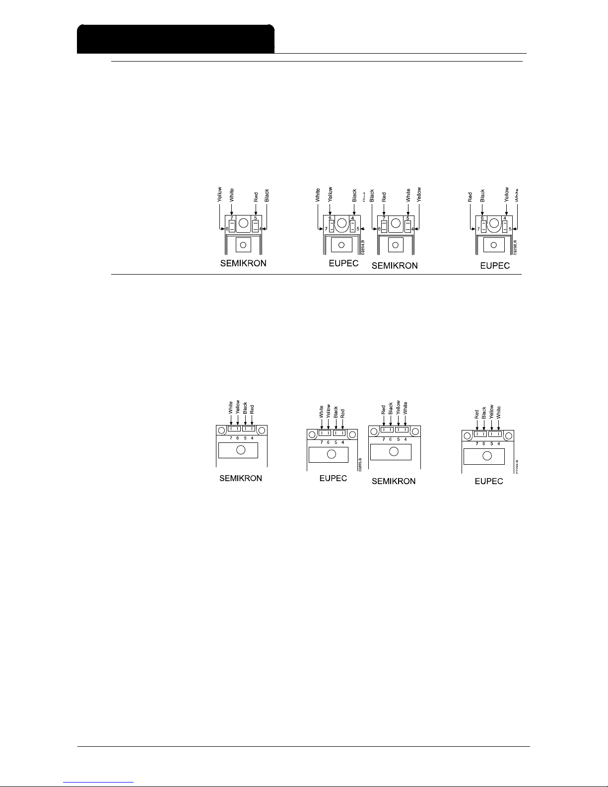
The connections between the Interface PCB and SCR depend on the revision of the Interface PCB (340-02471-00x,
340-02472-00x, 340-02473-00x). Connect the firing looms according to the diagrams below:
995-02557-00
995-02558-00
995-02559-00
995-02560-00
995-02561-00
PCB revision -00C PCB revision -00D or later
Page 19
SPARE PARTS
Page 18 CSX Series 710-02696-00C
995-02562-00
995-02563-00
995-02564-00
PCB revision -00C
PCB revision -00D or later
995-02565-00
995-02566-00
995-02567-00
PCB revision -00C
PCB revision -00D or later
Page 20

DISPOSAL INSTRUCTIONS
710-02696-00C CSX Series Page 19
Component/Fraction Environmental
conditions
Dismantling/Scrapping Characteristics
Aluminium No problems Re-melt. Separate from the rest to secure
high grade of recovery.
Steel No problems Re-melt. Separate from the rest to secure
high grade of recovery.
Wires No problems Re-melt in copper works with previous
shredding if necessary. PVC must be
incinerated at high temperature followed by
rapid cooling.
The isolation contains softeners,
gloves are recommended. Some
of the isolation is made of PVC.
Printed circuit boards
Current transformers
SCRs
Problems Copper recycling facilities, where all precious
metals are recovered and heavy metals and
other hazardous substances are bounded in
the remainder fraction.
All printed circuit boards and
components with plastics contain
flame retardant. The tin solder
contains lead.
Plastics Problems Controlled incineration or recycling Plastics are polycarbonate or
polycarbonate/ABS alloy and
contain glass and flame retardant.
Plastic - 10% glass reinforced polycarbonate
or polycarbonate ABS alloy
PCB
SCR
Current transformer
Bus bars - tin-plated copper
Cage clamps - yellow zinc
chromated steel
Sheet steel brackets zinc-plated
Spring - stainless steel
Heatsink - extruded aluminium
(black anodised)
Section 6 Disposal Instructions
Page 21

NOTES
Page 20 CSX Series 710-02696-00C
Page 22

AuCom Electronics Ltd
123 Wrights Road
PO Box 80208
Christchurch 8440
New Zealand
T +64 3 338 8280
F +64 3 338 8104
W www.aucom.com
 Loading...