

Page 1
1.
Caution Statements ......................................................................................................... 2
2.
Mechanical Installation .................................................................................................... 3
3.
Electrical Installation ........................................................................................................ 4
4.
Adjustments ......................................................................................................................... 7
5.
Troubleshooting ................................................................................................................ 8
6.
Accessories .......................................................................................................................... 9
7.
Specifications .................................................................................................................... 10
© 2015 AuCom Electronics Ltd. All Rights Reserved.
Contents
The examples and diagrams in this manual are included solely for illustrative purposes. The
information contained in this manual is subject to change at any time and without prior notice.
In no event will responsibility or liability be accepted for direct, indirect or consequential
damages resulting from the use or application of this equipment.
Ce manuel est également disponible en français à partir de www.aucom.com.
Dieses Handbuch ist auch in deutscher Sprache aus www.aucom.com.
Questo manuale è disponibile anche in italiano da www.aucom.com.
Este manual também está disponível em Português no site www.aucom.com.
Este manual también está disponible en español a partir de www.aucom.com.
富㈲ⅳṆ⏖✏Ḕ⛤ẵwww.aucom.com.
CSX
Page 2
CAUTION STATEMENTS
WARNING - ELECTRICAL SHOCK HAZARD
AVERTISSEMENT - DANGER D'ELECTROCUTION
GROUNDING AND BRANCH CIRCUIT PROTECTION
SHORT CIRCUIT
1. Caution Statements
Caution Statements cannot cover every potential cause of equipment damage but can
highlight common causes of damage. It is the installer's responsibility to read and understand
all instructions in this manual prior to installing, operating or maintaining the equipment, to
follow good electrical practice including applying appropriate personal protective equipment
and to seek advice before operating this equipment in a manner other than as described in
this manual.
x Isolate the CSX completely from the power supply before attempting any work on the
CSX or motor.
x Cables to the control inputs must be segregated from mains voltage and motor cabling.
x Some electronic contactor coils are not suitable for direct switching with PCB mount
relays. Consult the contactor manufacturer/supplier to confirm suitability.
x Do not apply incorrect voltages to the control input terminals.
x Do not connect power factor correction capacitors to the output of CSX soft starters. If
static power factor correction is employed, it must be connected to the supply side of
the soft starter.
The CSX contains dangerous voltages when connected to mains voltage. Only a
qualified electrician should carry out the electrical installation. Improper installation of
the motor or the CSX may cause equipment failure, serious injury or death. Follow
this manual and local electrical safety codes.
Le CSX contient des tensions dangereuses lorsqu'il est raccordé à l'alimentation
secteur. Seul un électricien compétent peut effectuer l'installation électrique. Une
mauvaise installation du moteur ou du CSX peut déclencher une panne
d'équipement, provoquer de graves blessures ou même la mort. Suivre les instructions
de ce manuel et des codes locaux concernant la sécurité électrique.
It is the responsibility of the user or person installing the CSX to provide proper
grounding and branch circuit protection according to local electrical safety codes.
The CSX is not short circuit proof. After severe overload or short circuit, the
operation of the CSX should be fully tested by an authorised service agent.
2 CSX User Manual 710-02407-00J
Page 3
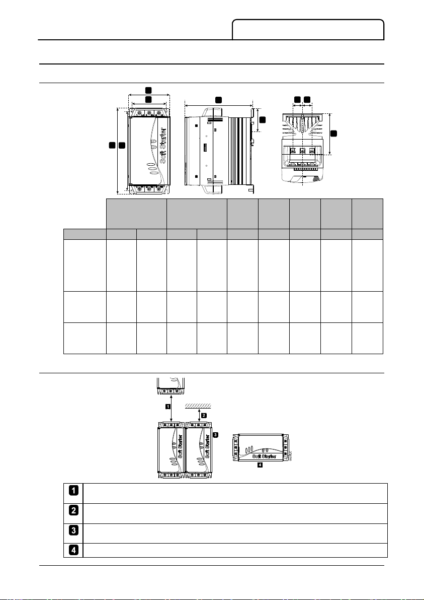
Width
mm (inch)
Height
mm (inch)
Depth
mm
(inch)
mm
(inch)
mm
(inch)
mm
(inch)
Weight
kg
(lb)
Model A B C D E F G H
MECHANICAL INSTALLATION
2. Mechanical Installation
2.1 Dimensions and Weights
A
B
DC
CSX-007
CSX-015
CSX-018 98 82 201 188 165 55 90.5 23 2.1
CSX-022 (3.85) (3.22) (7.91) (7.40) (6.49) (2.16) (3.6) (0.9) (4.6)
CSX-030
CSX-037
CSX-045 145 124 215 196 193 - 110.5 37 3.8
CSX-055 (5.70) (4.88) (8.46) (7.71) (7.59) (4.4) (1.5) (8.4)
CSX-075
CSX-090 200 160 240 216 214 - 114.5 51 6.1
CSX-110 (7.87) (6.30) (9.44) (8.50) (8.43) (4.5) (2.0) (13.5)
E
F
H H
G
03232.C
2.2 Physical Installation
CSX-007 ~ CSX-055: Allow 100 mm (3.9 inch) between soft starters.
CSX-075 ~ CSX-110: Allow 200 mm (7.9 inch) between soft starters.
CSX-007 ~ CSX-055: Allow 50 mm (2.0 inch) between the soft starter and solid surfaces.
CSX-075 ~ CSX-110: Allow 200 mm (7.9 inch) between the soft starter and solid surfaces.
Soft starters may be mounted side by side with no clearance (that is, if mounted without
communications modules).
The soft starter may be mounted on its side. Derate the soft starter's rated current by 15%.
710-02407-00J CSX User Manual 3
Page 4
ELECTRICAL INSTALLATION
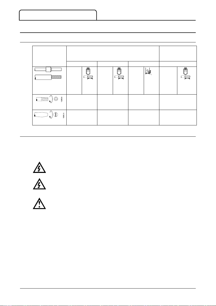
L1/1, L2/3, L3/5, T1/2, T2/4, T3/6
mm2 (AWG)
A1, A2, A3, 01, 02,
13, 14, 23, 24 mm
(AWG)
WARNING
AVERTISSEMENT
CAUTION
3. Electrical Installation
3.1 Power Terminations
007 - 030 037 - 055 075 - 110 007 - 110
10 - 35
10427.A
(8 - 2)
14 mm
(0.55
inch)
Torx (T20)
3 Nm
2.2 ft-lb
7 mm
3 Nm
2.2 ft-lb
25 - 50
10428.A
(4 1/10)
Torx (T20)
4 Nm
2.9 ft-lb
7 mm
4 Nm
2.9 ft-lb
14 mm
(0.55
inch)
3.2 Control Voltages
CSX soft starters can be supplied in either of two control voltage configurations:
CSX-xxx-xx-C1 ..... 110-240 VAC (+ 10% / - 15%) or 380-440 VAC (+ 10% / - 15%)
CSX-xxx-xx-C2 ..... 24 VAC/VDC (± 20%)
Always apply control voltage before (or with) mains voltage.
Toujours appliquer la tension de commande avant (ou en même temps que) la
tension secteur.
With 24 VAC/VDC use contacts rated for low voltage and low current (gold flash
or similar).
N.A.
10428.A
(0.43)
26
Ø8.5
(1.02)
(0.33)
mm
(inch)
n/a n/a
n/a
11
0.14 - 1.5
10429.A
(26 - 16)
3.5 mm
0.5 Nm max
4.4 in-lb max
6 mm
(0.24 inch)
2
10428.A
4 CSX User Manual 710-02407-00J
Page 5
WARNING
AVERTISSEMENT
CAUTION
3.3 Control Circuits
ELECTRICAL INSTALLATION
Isolate the CSX completely from the power supply before attempting any work on
the CSX or motor. Control terminals may be at phase voltage potential.
Isoler complètement le CSX de l'alimentation secteur avant de tenter toute
intervention sur le CSX ou sur le moteur. Les bornes de commande peuvent être
au potentiel de la tension de phase.
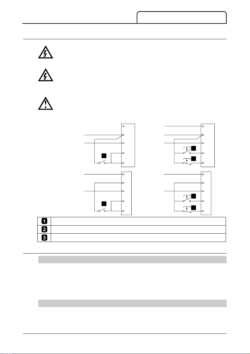
For CSX-xxx-xx-C2 (24 VAC/VDC control voltage) units you can connect an
external 24 VDC supply into the control input terminals 01, 02.
110-240 VAC
&
24 VAC/VDC
380-440 VAC
Start/stop. To reset a trip, open then close 02.
Start.
Stop. To reset a trip, open then close 02.
Two-wire control Three-wire control
A3
A1 (+)
A2 (-)
1
1
01
02
A3
A1
A2
01
02
03241.D
3.4 Outputs
Main Contactor Output
The Main Contactor output (terminals 13, 14) closes as soon as the soft starter receives a
start command and remains closed while the soft starter is controlling the motor (until the
motor starts a coast to stop, or until the end of a soft stop). The Main Contactor output will
also open if the soft starter trips.
The Main Contactor output can be used to directly control a main contactor coil.
Run Contactor Output
The relay (terminals 23, 24) operates four seconds after the set start ramp time is complete.
The relay can be used to operate a contactor for power factor correction capacitors, or to
signal soft starter run status to an automation system.
A3
A1 (+)
A2 (-)
2
01
3
02
A3
A1
A2
2
01
3
02
03242.D
710-02407-00J CSX User Manual 5
Page 6
ELECTRICAL INSTALLATION
M
K1
13, 14
23, 24
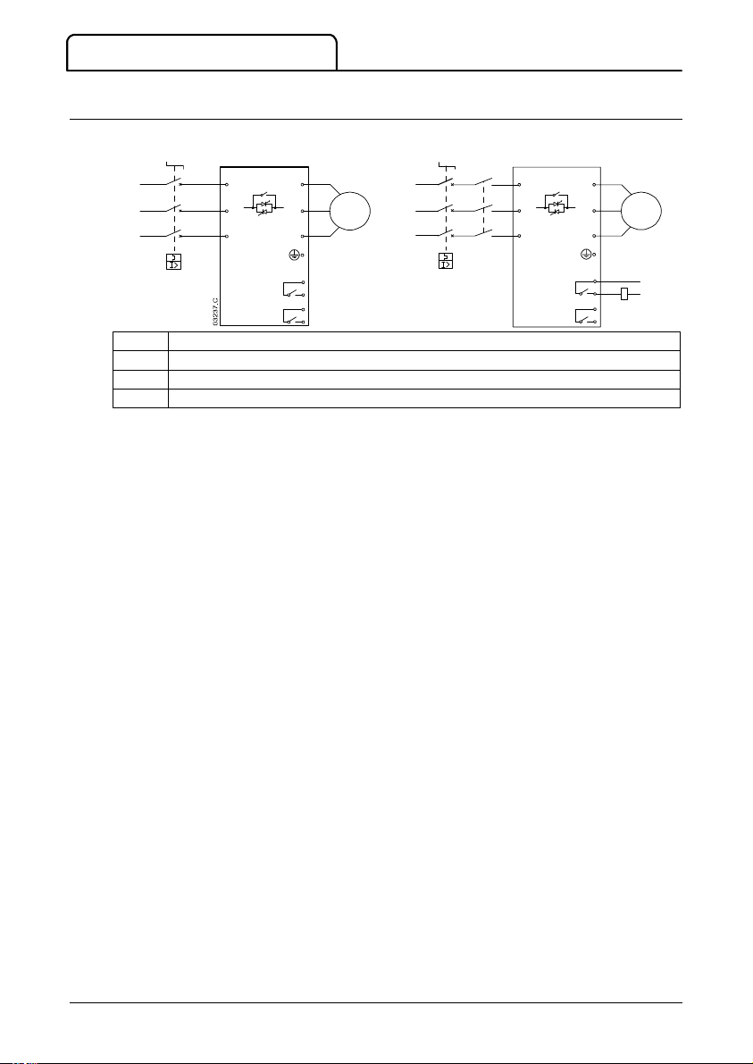
3.5 Electrical Schematics
Soft starter installed with a motor protection
circuit breaker
1/L1
3/L2
5/L3
2/T1
4/T2
6/T3
Soft starter installed with a motor protection
2/T1
4/T2
6/T3
M
circuit breaker and main contactor
K1
1/L1
M
3/L2
5/L3
Motor (three phase)
Main contactor
Main contactor output
Run contactor output
13
14
23
24
03238.D
13
14
23
K1
24
6 CSX User Manual 710-02407-00J
Page 7
Application Initial Start Voltage -
Suggested setting
NOTE
4. Adjustments
1
3
Initial Start Voltage
Start Ramp Time
Stop Ramp Time
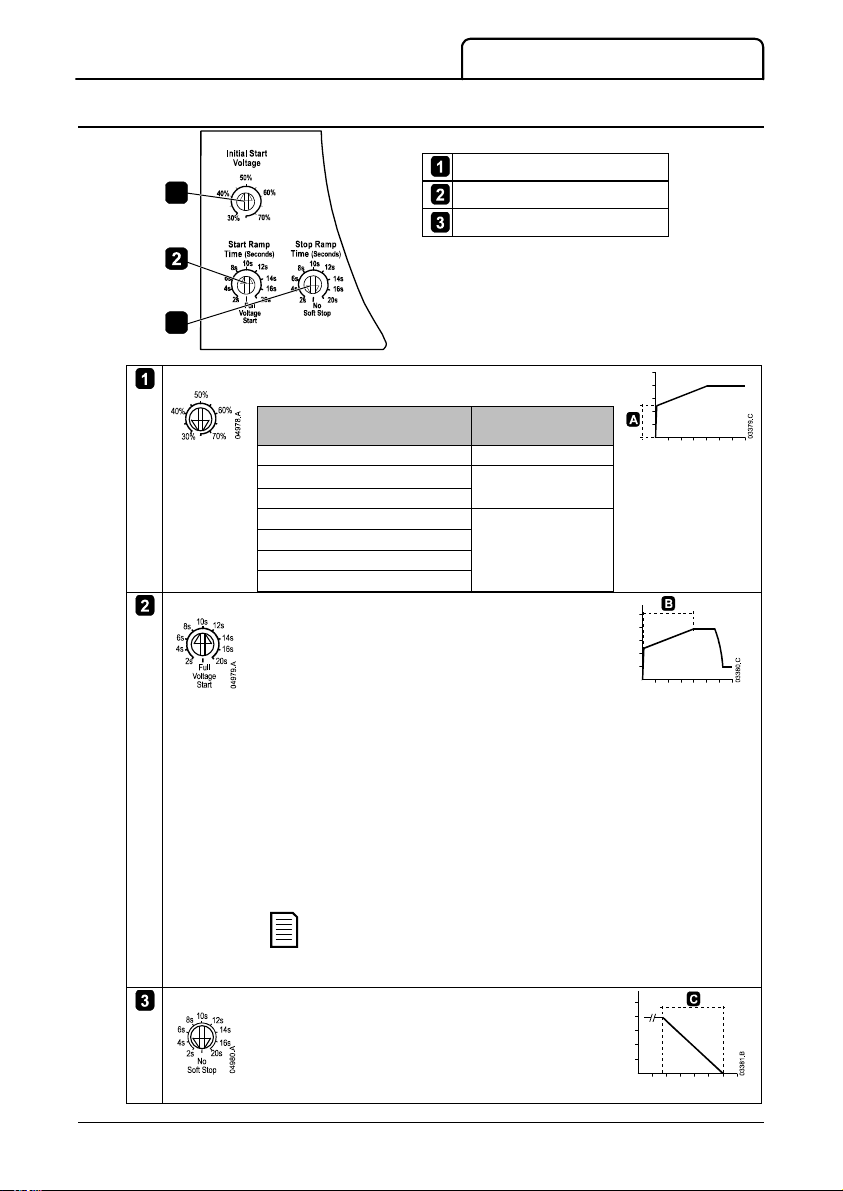
Select the initial start voltage (A).
Centrifugal Pump 50%
Submersible Pump 60%
Screw Compressor
Conveyor
Crusher 70%
Fan
Other applications
Select the start ramp time (B).
The start ramp defines how long the soft starter will
take to increase voltage from the initial start voltage to
full voltage.
The start ramp time does not control the time the
motor will take to reach full speed.
1. Set the start ramp time to 20 seconds.
2. Set the initial start voltage as required for the
3. Attach a current monitoring device to output T1.
4. Start the motor under normal load conditions.
5. Set start ramp time = t
Select the soft stop ramp time (C).
Soft stop extends the time soft starter takes to reduce
voltage to zero.
The ramp time does not control the time the motor will
take to stop completely.
Initial Start Voltage
Start Ramp Time
Stop Ramp Time
03243.D
application.
Record the time required for the measured current
to fall to (or below) the motor's rated full load
current (t
) then stop the motor.
1
.
1
The start ramp time must be long enough
for the motor to reach full speed before the
soft starter enters bypass mode.
ADJUSTMENTS
710-02407-00J CSX User Manual 7
Page 8
TROUBLESHOOTING
LED Status
Ready Run
Ready LED Description
5. Troubleshooting
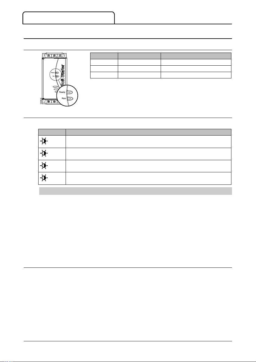
5.1 LEDs
Off No control power Motor not running
On Ready Motor running at full speed
Flash Starter tripped Motor starting or stopping
5.2 Trip Codes
The Ready LED will flash a different number of times to indicate the cause of the trip.
x 1
x 6
x 8
x 9
Power Circuit: Check mains supply (L1, L2, L3), motor circuit (T1, T2, T3), soft
starter SCRs and bypass relays.
Supply Frequency: Check mains voltage is available and supply frequency is in
range.
Network Communication Failure (between module and network): Check
network connections, settings and configuration.
Starter Communication Failure (between starter and module): Remove and refit
accessory module.
Supply Frequency Protection
The soft starter will trip on supply frequency if the frequency rises above 72 Hz or falls below
40 Hz for more than five seconds while the soft starter is running. These trip points are not
adjustable.
In pre-start, starting and stopping modes the high and low frequency limits both apply with no
time delay.
A supply frequency trip will also occur if:
x
all three input phases are lost while the soft starter is running
x
all three input phases fall below 120 VAC at start or while the soft starter is running
x
the line contactor opens while running
5.3 Reset
Trips can be cleared by pressing the Reset button on the soft starter, sending a Reset
command from the serial communications network, or by switching the control inputs.
To clear a trip via the control inputs, the soft starter requires a closed to open transition on
the stop input (02).
In three-wire control, use the external stop button to momentarily open the stop input
x
(open A1-02).
In two-wire control, if the soft starter tripped with a start signal present, remove the
x
start signal (open A1 to 01, 02).
The Reset button is located on the front of the unit, above the adjustment switches.
The soft starter will trip again immediately if the cause of the trip still exists.
8 CSX User Manual 710-02407-00J
Page 9
ACCESSORIES
6. Accessories
6.1 Finger Guard Kit
Finger guards may be specified for personnel safety. Finger guards fit over the soft starter
terminals to prevent accidental contact with live terminals. Finger guards provide IP20
protection when used with cable of diameter 22 mm or greater.
6.2 Remote Operator
The Remote Operator can control and monitor the soft starter's performance. Functionality
includes:
x
Operational control (Start, Stop, Reset, Quick Stop)
x
Starter status monitoring (Ready, Starting, Running, Stopping, Tripped)
Trip code display
x
6.3 Communication Interfaces
CSX soft starters support network communication via easy-to-install communications
interfaces. Each soft starter can support one communications interface at a time.
Available protocols:
Ethernet (Profinet, Modbus TCP, Ethernet/IP), Profibus, DeviceNet, Modbus RTU, and USB.
6.4 PC Software
WinMaster can be used with AuCom soft starters to provide the following functionality for
networks of up to 99 soft starters:
x
Operational control (Start, Stop, Reset, Quick Stop)
x
Starter status monitoring (Ready, Starting, Running, Stopping, Tripped)
To use WinMaster with the CSX, the soft starter must be fitted with a USB Module, Modbus
Module or a Remote Operator.
710-02407-00J CSX User Manual 9
Page 10
SPECIFICATIONS
Control voltage
Mains voltage
Nominal kW rating @400 VAC
Motor protection
AC53b 4-6:354
< 1000 metres
AC53b 4-20:340
< 1000 metres
40 °C 50 °C 40 °C 50 °C
AC53b 4-6:594
< 1000 metres
AC53b 4-20 580
< 1000 metres
40 °C 50 °C 40 °C 50 °C
7. Specifications
7.1 Model Code
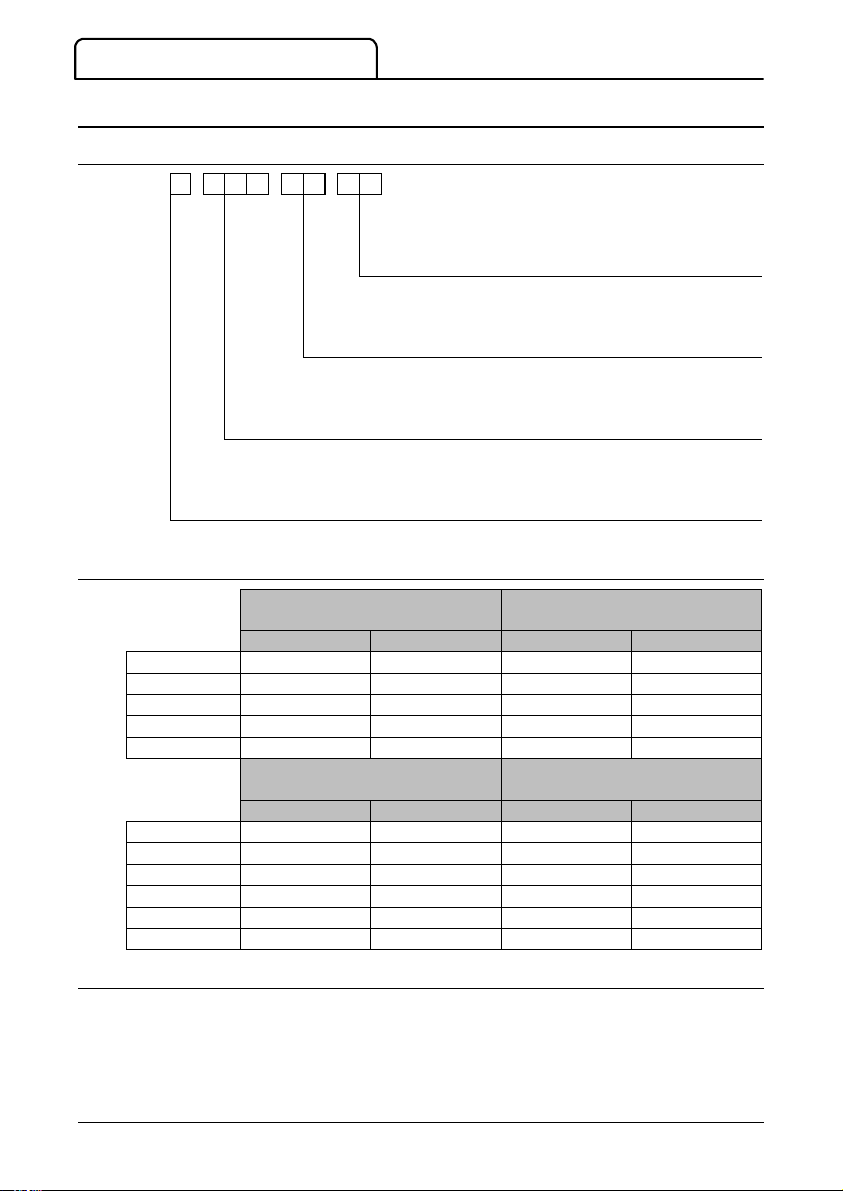
CSX -
7.2 Current Ratings
CSX-007 18 A 17 A 17 A 15 A
CSX-015 34 A 32 A 30 A 28 A
CSX-018 42 A 40 A 36 A 33 A
CSX-022 48 A 44 A 40 A 36 A
CSX-030 60 A 55 A 49 A 45 A
CSX-037 75 A 68 A 65 A 59 A
CSX-045 85 A 78 A 73 A 67 A
CSX-055 100 A 100 A 96 A 87 A
CSX-075 140 A 133 A 120 A 110 A
CSX-090 170 A 157 A 142 A 130 A
CSX-110 200 A 186 A 165 A 152 A
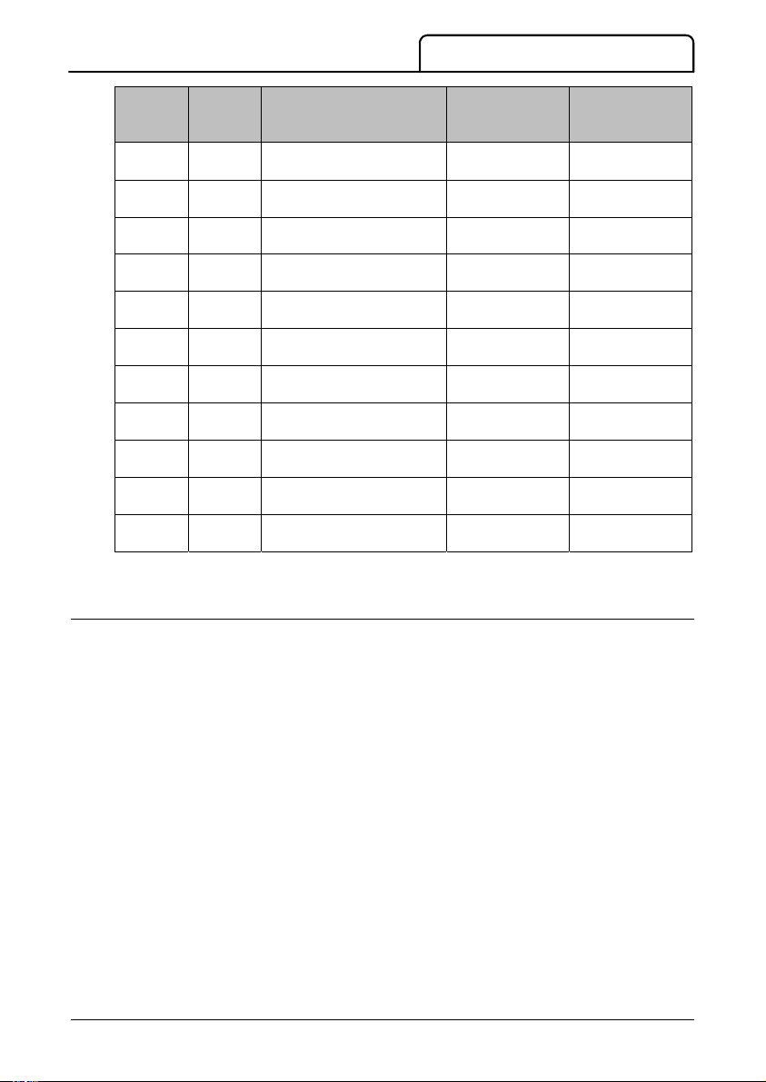
7.3 Semiconductor Fuses
Semiconductor fuses can be used with CSX soft starters to reduce the potential for damage
to SCRs from transient overload currents and for Type 2 coordination. CSX soft starters have
been tested to achieve Type 2 coordination with semiconductor fuses. Suitable Bussmann and
Ferraz/Mersen semiconductor fuses are detailed below.
- -
C
M
N
M
C1 = 110-240 VAC & 380-440 VAC
C2 = 24 VAC/VDC
V4 = 200 ~ 440 VAC
V6 = 200 ~ 575 VAC
30 kW AC53b 4-6-354
37 kW AC53b 4-6-594
Blank = Without motor protection
i
= With motor protection
10 CSX User Manual 710-02407-00J
Page 11
Model
SCR I2t
(A2s)
Ferraz/Mersen Fuse
European/IEC Style
(North American Style)
Bussmann Fuse
Square Body
(170M)
Bussmann Fuse
British Style
(BS88)
Mains Supply
Control Voltage (A1, A2, A3)
Inputs
CSX-007 1150
CSX-015 8000
CSX-018 10500
CSX-022 15000
CSX-030 18000
CSX-037 51200
CSX-045 80000
CSX-055 97000
CSX-075 168000
CSX-090 245000
CSX-110 320000
xxx = Blade Type. Contact Ferraz/Mersen for options.
6.6URD30xxxA0063
(A070URD30xxx0063)
6.6URD30xxxA0125
(A070URD30xxx0125)
6.6URD30xxxA0160
(A070URD30xxx0160)
6.6URD30xxxA0160
(A070URD30xxx0160)
6.6URD30xxxA0160
(A070URD30xxx0160)
6.6URD30xxxA0250
(A070URD30xxx0250)
6.6URD30xxxA0315
(A070URD30xxx0315)
6.6URD30xxxA0315
(A070URD30xxx0315)
6.6URD31xxxA0450
(A070URD31xxx0450)
6.6URD31xxxA0450
(A070URD31xxx0450)
6.6URD31xxxA0450
(A070URD31xxx0450)
170M-1314 63 FE
170M-1317 160 FEE
170M-1318 160 FEE
170M-1318 180 FM
170M-1319 180 FM
170M-1321 250 FM
170M-1321 250 FM
170M-1321 250 FM
170M-1322 500 FMM
170M-3022 500 FMM
170M-3022 500 FMM
SPECIFICATIONS
7.4 General Technical Data
Mains voltage (L1, L2, L3)
V4 ............................................................................................. 3 x 200 VAC ~ 440 VAC (+ 10% / - 15%)
V6 ............................................................................................. 3 x 200 VAC ~ 575 VAC (+ 10% / - 15%)
Mains frequency (at start) ................................................................................................................ 45 Hz to 66 Hz
Rated insulation voltage ................................................................................................................................... 600 VAC
Form designation ............................................................... Bypassed semiconductor motor starter form 1
CSX-xxx-xx-C1 ................................................................................................... 110-240 VAC (+ 10% / - 15%)
...............................................................................................................................or 380-440 VAC (+ 10% / - 15%)
CSX-xxx-xx-C2 ..................................................................................................................... 24 VAC/VDC (± 20%)
Current consumption (during run) ........................................................................................................ < 100 mA
Current consumption (inrush)
CSX-xxx-xx-C1 ..................................................................................................................................................... 10 A
CSX-xxx-xx-C2 ........................................................................................................................................................ 2 A
Start (terminal 01) .................................................................................................................................. Normally open
........................................................................................... 150 k: @ 300 VAC and 5.6 k: @ 24 VAC/VDC
Stop (terminal 02) ............................................................................................................................... Normally closed
........................................................................................... 150 k: @ 300 VAC and 5.6 k: @ 24 VAC/VDC
710-02407-00J CSX User Manual 11
Page 12

SPECIFICATIONS
Outputs
Environmental
EMC Emission
EMC Immunity
Short Circuit
Heat Dissipation
Standards Approvals
Operational Life
Main contactor (terminals 13, 14) ................................................................................................ Normally open
..................................................................................................................... 6 A, 30 VDC / 6 A, 250 VAC resistive
Run relay (terminals 23, 24) ............................................................................................................... Normally open
..................................................................................................................... 6 A, 30 VDC / 6 A, 250 VAC resistive
Degree of Protection CSX-007 to CSX-055 ................................................................................................ IP20
Degree of Protection CSX-075 to CSX-110 ................................................................................................ IP00
Operating temperature ............................................................................................................. - 10 °C to + 60 °C
Storage temperature ..................................... -25 °C to + 60 °C (to +70 °C for less than 24 hours)
Humidity ....................................................................................................................... 5% to 95% Relative Humidity
Pollution degree ............................................................................................................................. Pollution Degree 3
Vibration ........................................................................................................................ IEC 60068 Test Fc Sinusoidal
............................................................................................................... 4 Hz to 13.2 Hz: ± 1 mm displacement
........................................................................................................................................... 13.2 Hz to 200 Hz: ± 0.7 g
Equipment class (EMC) ......................................................................................................................................... Class B
Conducted radio frequency emission .................................. 0.15 MHz to 0.5 MHz: < 56-46 dB (μV)
............................................................................................................................ 0.5 MHz to 5 MHz: < 46 dB (μV)
............................................................................................................................. 5 MHz to 30 MHz: < 50 dB (μV)
Radiated radio frequency emission ............................................ 30 MHz to 230 MHz: < 30 dB (μV/m)
............................................................................................................ 230 MHz to 1000 MHz: < 37 dB (μV/m)
Electrostatic discharge ............................................................... 4 kV contact discharge, 8 kV air discharge
Radio frequency electromagnetic field .................................... 0.15 MHz to 1000 MHz: 140 dB (μV)
Rated impulse withstand voltage (Fast transients 5/50 ns) . 2 kV line to earth, 1 kV line to line
Voltage dip and short time interruption ........................................... 100 ms (at 40% nominal voltage)
Harmonics and distortion ......................................................... IEC61000-2-4 (Class 3), EN/IEC61800-3
Rated short-circuit current CSX-007 to CSX-022 ................................................................................. 5 kA 1
Rated short-circuit current CSX-030 to CSX-110 .............................................................................. 10 kA
1
These short circuit ratings are with fuses used as given in the table under
page 10.
Semiconductor Fuses
During Start ............................................................................................................................................ 3 watts / ampere
During Run ................................................................................................................................................ 10 watts typical
C9 .................................................................................................................................................................... IEC 60947-4-2
CE ...................................................................................................................................................................... IEC 60947-4-2
CCC ....................................................................................................................................................................... GB 14048.6
EAC .................................................................................................................. TP TC 004/2011, TP TC 020/2011
Marine .................................................................................................................. Lloyds Marine No 1 Specification
UL / C-UL .................................................................................................................................................................... UL 508
CSX-007~055 ............................................................................................................................ 1,000,000 operations
CSX-075~110 ................................................................................................................................... 30,000 operations
on
1
È710-02407-00J*ËÍ
710-02407-00J
12 CSX User Manual 710-02407-00J
 Loading...