

Page 1
USER MANUAL
AUBO-i10 & CB4
Please read this manual carefully before using the product.
Page 2

Page 3

User Manual
AUBO-i10 & CB4
Translate Version 4.5
Published by AUBO (Beijing) Robotics Technology Co, Ltd.
This manual is applicable to AUBORPE V 4.5. For details, please refer to the version information
section of this manual. Please check the actual product version information carefully before use to
ensure consistency.
Page 4

The user manual will be checked and revised periodically, and the updated content will appear on the latest
version.
The information in this manual is subject to change without notice and should not be regarded as a
commitment by AUBO (Beijing) Robotics Technology Co., Ltd.
AUBO (Beijing) Robotics Technology Co., Ltd. assumes no responsibility for any errors or omissions in this
document. AUBO (Beijing) Robotics Technology Co., Ltd. assumes no responsibility for incidental or
consequential damages arising from use of this manual and products described herein.
Please read this manual before install or use.
Please keep this manual to read and as reference any time.
The pictures in this manual are for reference only, please refer to the actual product received.
Copyright © 2015-2018 AUBO All rights reserved
Page 5
V4.5
©2015-2019 AUBO.All rights reserved. i
CATALOG
CATALOG ................................................................................................................................ I
PREFACE ............................................................................................................................. VII
COMPONENTS OF AUBO-I10 ROBOT ........................................................................ VIII
MORE INFORMATION ................................................................................................... VIII
1. SAFETY ............................................................................................................................. 9
Introduction ................................................................................................................... 9
Warning Symbols in this Manual .................................................................................. 9
Safety Precautions ....................................................................................................... 10
General .............................................................................................................. 10
Terms and Conditions ....................................................................................... 10
Operator safety .................................................................................................. 14
Responsibility and standard ........................................................................................ 15
Hazard Identification .................................................................................................. 17
Intended use ................................................................................................................ 18
Emergency situations .................................................................................................. 19
Emergency stop device ..................................................................................... 19
Recovering from the emergency condition ....................................................... 20
Emergency move for joint ................................................................................ 20
Excessive force protection ................................................................................ 20
2. TRANSPORTATION AND PRECAUTIONS .............................................................. 21
3. MAINTENANCE, REPAIR AND DISPOSAL ............................................................. 23
Maintenance and repair ............................................................................................... 23
Disposal....................................................................................................................... 24
4. WARRANTIES ................................................................................................................ 25
Product Warranty ........................................................................................................ 25
Disclaimer ................................................................................................................... 25
5. ROBOT HARDWARE COMPOSITION ..................................................................... 27
6. ROBOT INSTALLATION ............................................................................................. 29
Brief installation steps................................................................................................. 29
Important safety instructions....................................................................................... 29
Workspace of the Robot .............................................................................................. 30
Mechanical dimensions of manipulator ............................................................ 30
Effective working range .................................................................................... 31
Page 6
V4.5
©2015-2019 AUBO.All rights reserved. ii
Hardware Installation .................................................................................................. 32
The Manipulator Base ....................................................................................... 32
Manipulator Installation .................................................................................... 33
End-effector Installation ............................................................................................. 35
Mechanical structure size of end-effector flange .............................................. 35
Cable connection ......................................................................................................... 36
7. THE I SERIES STANDARD CONTROL BOX ........................................................... 41
Introduction ................................................................................................................. 41
Electrical warnings and cautions ................................................................................ 42
Control box panel introduction ................................................................................... 42
Control box front panel ..................................................................................... 43
Control box side panel ...................................................................................... 44
Control box back panel ..................................................................................... 47
Selection of working mode ......................................................................................... 48
Manual mode .................................................................................................... 49
Linkage mode.................................................................................................... 49
8. INTERNAL ELECTRICAL INTERFACE .................................................................. 53
Introduction ................................................................................................................. 53
Electrical warnings and cautions ................................................................................ 53
Control box communication interface ........................................................................ 54
Control box I/O power supply .................................................................................... 55
Internal power supply ....................................................................................... 55
External power supply ...................................................................................... 55
Safety I/O .................................................................................................................... 56
Introduction ....................................................................................................... 56
Safety Tips ........................................................................................................ 56
Safety I / O function definition ......................................................................... 56
Default Safety Configuration ............................................................................ 57
External Emergency Stop Input ........................................................................ 58
Safeguard stop Input ......................................................................................... 59
Reduce Mode Input ........................................................................................... 61
Safeguard stop Resert Input .............................................................................. 62
Enabling Device Input ...................................................................................... 63
Operational Mode Input .................................................................................. 64
Hand Guiding Enable Input ............................................................................ 64
System Stop Input ........................................................................................... 65
Robot Emergency Stop Output ....................................................................... 66
Robot Moving Output ..................................................................................... 67
Robot Not Stopping Output ............................................................................ 68
Reduced Mode Output .................................................................................... 69
Not Reduced Mode Output ............................................................................. 70
Page 7
V4.5
©2015-2019 AUBO.All rights reserved. iii
8.5.18 System Error Output ....................................................................................... 71
Internal I/O .................................................................................................................. 72
General I/O.................................................................................................................. 73
General purpose digital I/O interface ................................................................ 73
Example ................................................................................................................................ 74
Analog I/O interface .......................................................................................... 76
Example ................................................................................................................................ 77
Clear alarm signal interface .............................................................................. 78
Remote switch control I/O interface ........................................................................... 78
Remote power on .............................................................................................. 79
Remote power off ............................................................................................. 79
Linkage Control I/O Interface ..................................................................................... 79
Robot Tool I/O Interface ........................................................................................... 81
9. GETTING STARTED ..................................................................................................... 84
Basic function introduction ......................................................................................... 84
Installing the robot system .......................................................................................... 85
Power on the manipulator ........................................................................................... 85
Preparation ........................................................................................................ 85
Power on System............................................................................................... 86
Power off the manipulator .......................................................................................... 87
Start system quick ....................................................................................................... 87
10. TEACH PENDANT ..................................................................................................... 88
Instruction ................................................................................................................. 88
Teach Pendant Operation Interface ........................................................................... 88
User login ........................................................................................................ 88
Initial Interface ................................................................................................ 89
Robot Movement Control ............................................................................... 90
Robot Teaching User Interface .............................................................................................. 90
1 Currently logged in user ..................................................................................................... 91
2 Logout button ..................................................................................................................... 91
3 Software shut down button ................................................................................................ 91
4 Menu .................................................................................................................................. 91
5 Robot 3D display window.................................................................................................. 92
6 Simulation/real control switch button ................................................................................ 93
7 Step Mode Control ............................................................................................................. 93
8 Position control .................................................................................................................. 93
9 Coordinate system .............................................................................................................. 94
9 User-defined coordinate system ......................................................................................... 95
10 Robot real-time status parameter display ......................................................................... 95
11 Target selection ................................................................................................................ 95
12 Orientation Control .......................................................................................................... 96
Page 8
V4.5
©2015-2019 AUBO.All rights reserved. iv
13 Joint axis control .............................................................................................................. 97
14 Zero Pose, Init Pose ......................................................................................................... 97
15 Motion speed control ....................................................................................................... 98
16 Date and time display ....................................................................................................... 98
17 Speed control ................................................................................................................... 98
Robot I/O settings and status display ........................................................................ 98
Controller I/O Tab ........................................................................................... 99
User I/O Tab .................................................................................................. 100
Tool I/O Tab .................................................................................................. 100
Robot Setting Tab.................................................................................................... 102
InitPose ......................................................................................................... 102
Tool Calibration ............................................................................................ 103
Tool Kinematics Calibraton ................................................................................................ 104
Tool Dynamics Calibration ................................................................................................. 106
Tool Calibrate ...................................................................................................................... 107
Coordinate Calibration .................................................................................. 108
Robot Safety Settings .............................................................................................. 112
System Setting tab................................................................................................... 113
Language Tab ................................................................................................ 113
Date& Time tab. ............................................................................................ 114
Network Tab .................................................................................................. 115
Password Tab ................................................................................................ 115
Lock Screen .................................................................................................. 116
Update Tab .................................................................................................... 117
Factory Reset ...................................................................................................................... 117
Update Software/Firmware ................................................................................................. 118
File Export .......................................................................................................................... 118
Extensions ............................................................................................................... 119
System Info Tab ...................................................................................................... 122
11. ONLINE PROGRAMMING .................................................................................... 124
Instruction ............................................................................................................... 124
Function Module Description ................................................................................. 126
Text Box Editor ............................................................................................. 126
Project Tab .............................................................................................................. 126
New Project ................................................................................................... 126
Load Project .................................................................................................. 128
Save Project ................................................................................................... 129
Default Project .............................................................................................. 130
Automove tab ................................................................................................ 131
Procedure ...................................................................................................... 132
Procedure (process) ................................................................................................. 133
Calling Subproject Commands(Procedure) ............................................. 133
Page 9
V4.5
©2015-2019 AUBO.All rights reserved. v
Move Condition.................................................................................................... 135
Type of Move ................................................................................................ 136
Move Joint .......................................................................................................................... 136
Move Line ........................................................................................................................... 137
Move Track ......................................................................................................................... 138
Waypoint ....................................................................................................... 140
Basic Command & Condition Tabs ......................................................................... 141
Loop .............................................................................................................. 142
Break ............................................................................................................. 142
Continue ........................................................................................................ 142
If…else .......................................................................................................... 143
Switch...Case...Default .................................................................................. 144
Set .................................................................................................................. 145
Wait ............................................................................................................... 146
Line Comment ............................................................................................... 146
Block Comment ............................................................................................ 147
Goto ............................................................................................................. 147
Message ....................................................................................................... 148
Empty .......................................................................................................... 149
Advanced Command & Condition Tabs ................................................................. 149
Thread ........................................................................................................... 149
Script ............................................................................................................. 149
Offline Record ............................................................................................... 150
Record Track ........................................................................................................... 151
Variable Tab ............................................................................................................. 153
Timer ..................................................................................................................... 154
Inserch Timer .............................................................................................. 154
Timer Status Display ................................................................................... 155
Simulation model .................................................................................................. 155
Scripts file configuration ....................................................................................... 156
APPENDIX ............................................................................................................................... I
A GLOSSARY .......................................................................................................................... I
B CERTIFICATION ............................................................................................................... II
C STOPPING TIME & STOPPING DISTANCE .............................................................. IV
D GUIDELINE ........................................................................................................................ V
E TECHNICAL SPECIFICATION .................................................................................... VI
F PAYLOAD ......................................................................................................................... VII
G ALARM INFORMATION & DESCRIPTION OF GENERAL PROBLEM ........... VIII
Page 10

V4.5
©2015-2019 AUBO.All rights reserved. vi
Page 11
V4.5
©2015-2019 AUBO.All rights reserved. vii
Preface
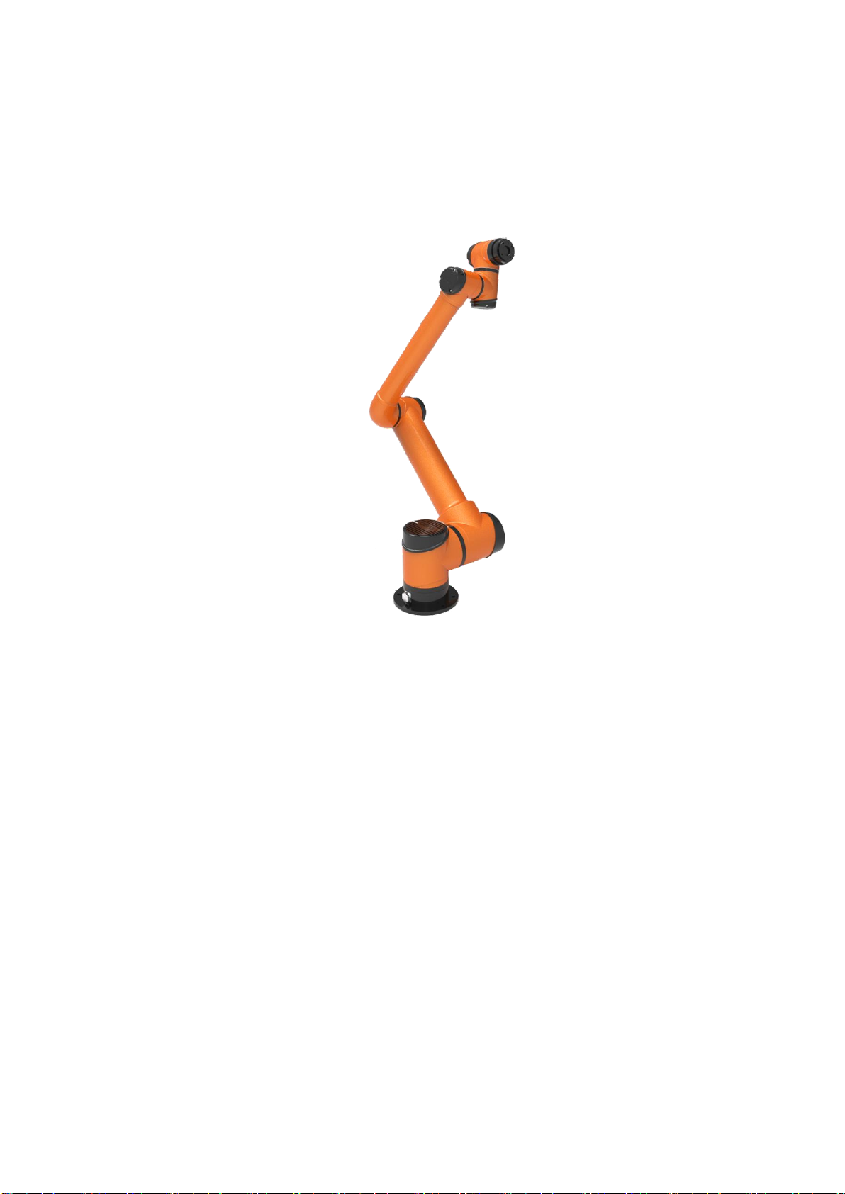
Thank you for purchasing this lightweight modular industrial robot with 6 degrees of freedom, AUBO-i10,
which is researched and developed by AUBO (Beijing) Robotics Technology Co., Ltd.
AUBO-i10
AUBO series robot adopts the fully modular design and uses system towards developers. Users can develop their
own robot control system based on the application interaface provide by the AUBO platform. Meanwhile, AUBO
robot is equipped with a dedicated programmable operation interface, which allows the user to observe robot’s
operating status in real time, carry out manyrobot control settings, and perform offline simulation. This can
improve the efficiency of practical application greatly.
AUBO-i10, the second generation of intelligent lightweight 6 DOF modular collaborative robot, whose payload
is 10kg, is one of AUBO series modular collaborative robots.
Page 12
V4.5
©2015-2019 AUBO.All rights reserved. viii
Components of AUBO-i10 Robot
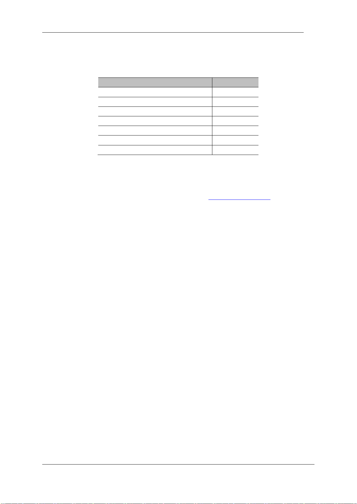
The components of the AUBO-i10 robot are listed as below.
Name
Quantity
Manipulator AUBO-i10
1
Teach Pendant
1
Control Box
1
Teach Pendant cable
1
Manipulator cable
1
Power cable
1
Manipulator base(optional)
1
Product outline structure is shown in picture above.
More Information
If you need more information, please visit our official website at: www.aubo-robotics.com
Page 13
V4.5
©2015-2019 AUBO.All rights reserved. 9
1. SAFETY
Introduction
This chapter introduces the principles and norms that should be followed when operating a robot or
robot systems. Integrators and users must read the relevant description in this manual carefully and
fully understand and strictly adhere to thewarning symbols in the contents. Because of the
complexity and highly risks of the robot system, operators need to be fully aware of the operation
risks and follow the requirements and specifications in this manual. Both the integrators and users
should have adequate safety awareness and follow the Industrial robots’ safety regulations, ISO
10218.
Warning Symbols in this Manual
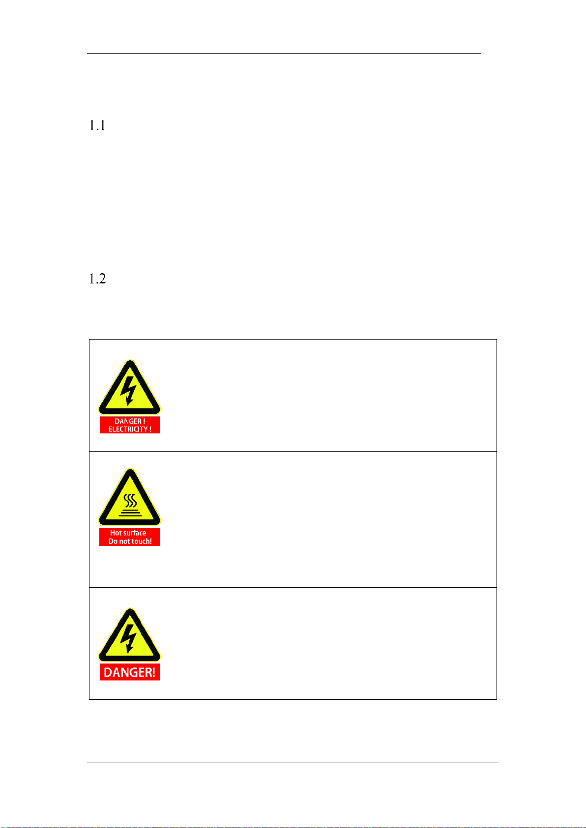
The table below defines the captions specifying the danger levels used throughout this manual.
These warnings, which are relevant to safety, must be observed.
This indicates an imminently hazardous electrical situation which, if not avoided,
could result in death or serious injury.
This indicates a potentially hazardous hot surface which, if touched, could result
in injury.
This indicates an imminently hazardous situation which, if not avoided, could
result in injury or major damage to the equipment.
Page 14
V4.5
©2015-2019 AUBO.All rights reserved. 10
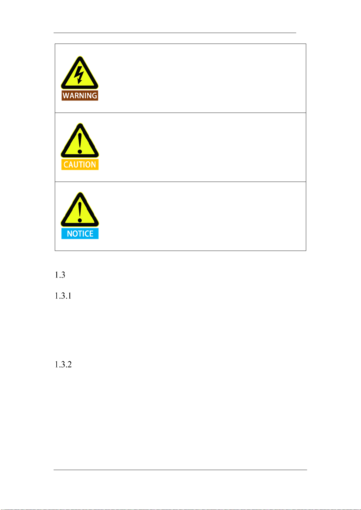
This indicates a potentially hazardous electrical situation which, if not avoided,
could result in injury or major damage to the equipment.
This indicates a potentially situation which, if not avoided, could result in injury
or major damage to the equipment. Marked with this symbol, depending on the
circumstances, sometimes may have significant consequences.
This indicates a situation which, if not avoided, could result in injury or major
damage to the equipment. Marked with this symbol, depending on the
circumstances, sometimes may have significant consequences.
Safety Precautions
General
This manual includes safety precautions for protecting the user and preventing damage to the
machine. Users need to learn all the relevant descriptions and fully understand the safety precautions.
In this manual, we try to describe all the various situation as much as possible. However, we cannot
describe all the matters, which must not be done or which cannot be done, because there are so many
possibilities.
Terms and Conditions
The following basic information needs to be understood and followed when using the robot or robot
system for the first time. Also, other safety-related information will be introduced in other parts of
this manual. However, it may not cover everything. In practical applications, it is necessary to
analyze specific issues.
Page 15
V4.5
©2015-2019 AUBO.All rights reserved. 11
1. Make sure to install the robot and all electrical equipment according to the
manual requirements and specifications.
2. Make sure to conduct a preliminary test and have inspection forrobots and its
protection systems before using the robot or putting it into productionfor the
first time.
3. Make sure to check the system and equipment for completion, operational
safety, and any damage that can be detected before starting the system and
equipment for the first time. The test needs to confirm whether it accords with
valid safety production rules and regulations in country or region. All safety
functions must be tested.
4. Make sure that all safety parameters and user programs are correct, and all
safety functions are working normally. A qualified robotics operator is needed
to check each safety function. Only pass the thorough, careful safety test and
reach the safe level, we can power on the robot.
1. Installation and commissioning needs to be performed by professionals in
accordance with the installation standards.
2. When the robot is installed, a comprehensive risk assessment is necessary, and
the test results need to be recorded in a report.
3. Set and modify the safety parameters by a qualified person. Use password or
isolation measures to prevent unauthorized people from setting and modifying
safety parameters. After a safety parameter is modified, the related safety
functions need to be analyzed.
4. When the robot is in an accident or abnormal operation, the emergency stop
switch needs to be pressed down to stop the movement.
5. AUBO-i10 joint module has brakes inside, it will remain manipulator’s pose
when power outage occurred. Don’t power on and power off frequently. It is
recommended that the time interval of each switch should be more than 10s.
6. AUBO-i10 has collision detecting function. When the external force of the
manipulator is beyond the users’ safety range, the manipulator will
automatically stop to prevent the robot or operator from damage or injury.
This function is a particularly for the safety of cooperative work, but robot
system must be in the normal operating range and use the AUBO series
control box. If the user develops the controller personally, the robot will not
have the functions above, and all the dangerous consequences are undertaken
by its owner.
Page 16
V4.5
©2015-2019 AUBO.All rights reserved. 12
1. Make sure that the robot's joints and tools are installed properly and safely.
2. Make sure that there is enough space for the manipulator to move freely.
3. Don’t use robot if the robot is damaged.
4. Do not connect any safety equipment to normal I/O. Use safety-related
interfaces only.
5. Make sure to use the correct installation settings (e.g. the robot's mounting
angle, TCP weight, TCP offset, security configuration). Save and load the
installations file along with the program.
6. Tools and barriers should not have sharp edges or pinch points. Make sure that
all people keep their heads and faces outside the reach of the robot.
7. Be aware of robot’s movement when using the teach pendant.
8. Any strike would release a large amount of kinetic energy, which is much
higher than the case of high speed and high payload.
9. The different mechanical linking may increase the risk or lead to new dangers.
Make sure to perform a comprehensive risk assessment for entire installation.
Always choose the highest-level performance when different safety and
emergency shutdown performance level is needed. Make sure to read and
understand all the devices’ manual used for installation.
10. Do not modify the robot. Changes to the robot may cause unpredictable
danger to the integrator. The robots authorize restructuring need in accordance
with the latest version of all relevant service manuals. If the robot is changed
or altered in any way, AUBO (Beijing) Robotics Technology Co., Ltd
disclaims all liability.
11. User needs to check the insulation and protection measures before
transportation.
12. Transporting robots must follow the transport requirements. Handing
carefully and avoid t bumps.
1. The robot and control box generate heat during operation. Do not handle or
touch the robot while rthe robot is working or just stop working.
2. To cool the robot down, power off the robot and wait for one hour.
3. Never stick fingers behind the internal cover of the control box.
Page 17
V4.5
©2015-2019 AUBO.All rights reserved. 13
1. When the robot is combined with or working with machines capable of
damaging the robot, then it is highly recommended to test all the functions of
the robot and the robot program separately. It is recommended to test the
robot program using temporary waypoints outside the workspace of other
machines.
2. AUBO (Beijing) Robotics Technology Co., Ltd cannot be held responsible for
any damages caused to the robot or to other equipment due to programming
errors or malfunctioning of the robot.
3. Don't expose the robot to a permanent magnetic field. Very strong magnetic
fields can damage the robot.
Page 18
V4.5
©2015-2019 AUBO.All rights reserved. 14
Operator safety
In the operation of the robot system, we must ensure the safety of the operators first. The general
precautions are listed in the table below. Please take appropriate measures to ensure the safety of
operators.
1. Each operator who uses the robotic system should be trained through a
training course hosted by AUBO (Beijing) Robotics Technology Co., Ltd.
Users need to make sure to fully grasp the safe and standardized operating
procedures with the robot operating qualifications. Please inquire for
training details, mail [email protected]
2. Do not wear loose clothing or jewelry when working with the robot. Make
sure long hair is tied back when working with the robot.
3. When the device is running, even if the robot seems to stop, it is possible
that robot is waiting for the signal and in the upcoming action status. Even
in such state, it should be considered as the robot is in action.
4. A line should be drew to mark the range of motion of the robot to let the
operator knows the robot’s, including the holding tools, (like mechanical
hand or tools) operating range.
5. Make sure to set security-building measures (for example, rails, ropes, or
protective screen) near the robot operating area to protect the operator
and surrounding crowd. The lock should be set as needed so that those
who are not operators cannot access the robot power supply.
6. When using the operation panel or the teach pendant, make sure to take off
the gloves in case of operational errors.
7. Pushing or pulling the robot arm (at least 700N), force the joint to move in
the emergency or abnormal condition (like a person is caught in or
surrounded by a robot). Manually move the robot arm without electric
drive only for emergency, and it may damage the joints.
Page 19

V4.5
©2015-2019 AUBO.All rights reserved. 15
Responsibility and standard
AUBO-i10 can be combined with other equipments to form a complete machine, and itself is not
complete. The information in this manual does not cover how to design, install and operate a
complete robot, nor does it cover all peripheral equipments that can influence the safety of the
complete system. The safety of installing a complete robot is determined by how it integrated.
Integrators must follow the standards and regulations and laws of the country where the robot is
installed to perform a risk assessment for its system design and installation. Risk assessment is one
of the most important things that integrators must done. Guidance on the risk assessment process
may be found in the following standards.
• ISO 12100:2010 Safety of machinery - General principles for design - Risk assessment and
risk reduction.
• ISO 10218-2:2011 Robots and robotic devices - Safety requirements - Part 2: Industrial robot
systems and integration.
• RIA TR R15.306-2014 Technical Report for Industrial Robots and Robot Systems - Safety
Requirements, Task-based Risk Assessment Methodology.
• ANSI B11.0-2010 Safety of Machinery; General Requirements & Risk Assessment.
AUBO robot integrators need to fulfill but not limited to the following responsibilities:
• Comprehensive risk assessment of complete robot system;
• Make sure the whole system design and installation is correct;
• Provide training to users and personnel;
• Create operational specifications for a complete system, specify instructions for process;
• Establish appropriate safety measures;
• Use appropriate methods to eliminate or minimize all hazards to acceptable level in the final
installation;
• Convey the residual risk to the users;
• Mark the logo and contact information of the integrators on the robot;
• Archive technical file
Guidance on how to find and read applicable standards and laws is provided on: www.aubo-
robotics.com
All safety information contained in this manual are not considered as a guarantee for AUBO (Beijing)
Robotics Technology Co., Ltd. Even if all the safety instructions are observed, the personnel injury
or equipment damage caused by the operator is still likely to occur.
AUBO (Beijing) Robotics Technology Co., Ltd is committed to continuously improve the reliability
and performance of the product. Therefore, we reserve the right to upgrade products without notice.
Page 20

V4.5
©2015-2019 AUBO.All rights reserved. 16
AUBO (Beijing) Robotics Technology Co., Ltd seeks to ensure the accuracy and reliability of the
contents in this manual but is not responsible for any errors or omissions.
Page 21

V4.5
©2015-2019 AUBO.All rights reserved. 17
Hazard Identification
Risk assessment should consider all potential contacts and foreseeable misuse between robot and
operator. Operator's neck, face and head should not be exposed in case of collision. Without using
peripheral safety devices, the robot needs to perform a risk assessment first to determine whether
the risk is unacceptable, such as:
• The risk of using a sharp end-effector or tool connector;
• The risk of processing toxic or other hazardous substances;
• Fingers being caught by robot base or joint;
• The risk of being hit by manipulator;
• The danger due to incompletely fix of manipulator or connected tool;
• Danger due to impactbetween a heavy payload and a soild surface.
Integrators must measure these dangers and its associated risk level through a risk assessment.
Identify and implement appropriate measures to reducer the risk to acceptable level. However,
Integrators should be aware that specific robotic equipment may have other dangers.
Combine the inherent safety design which applied by AUBO robot with the safety specifications or
risk assessment performed by integrators and users, risks that are associated with AUBO-i10
collaborative operation should be lower to reasonable and practicable level. Any residual risks
before installing will be conveyed to integrators and users through this manual. If integrator's risk
assessment shows that there may have unacceptable risks in specific applications, integrators must
take appropriate risk reduction measures to eliminate or minimize these risks to acceptable level. It
is not safe to use before taking appropriate risk reduction measures (If necessary).
If perform noncooperative installation (for example, when using dangerous tools), risk assessment
may infer that integrators need to connect additional security devices (such as a boot device) when
it is programming to ensure the safety of personnel and equipment.
Page 22

V4.5
©2015-2019 AUBO.All rights reserved. 18
Intended use
AUBO robot is industrial only and intended for operating or fixing tools or device or for
processing or transferring components or products. AUBO robot can only be used under specified
conditions. For details about the operating environment and conditions, see appendix.
AUBO robot has a special level of safety for cooperative operation. It can perform collaborative
operation, which means it can be used without setting peripheral safety device. However, it can
only be used under non-hazardous circumstance which has passed the risk assessment. On the
premise that not using any security device and sensing device, there will be no unacceptable risk
when personnel or other objects in workplace (like tool, equipment, surfaces etc.) has expected or
unexpected contact with AUBO robot or its end-effector.
Robot controllers and robots can only be used in general industrial equipment. Any use or
application deviating from the intended use is deemed to be impermissible misuse. This includes,
but is not limited to:
• Use in potentially flammable and explosive environments;
• Use to move or carry people or other animals;
• For devices such as medical devices that inbolbe human life
• Use to have a major impact on social and public;
• Use under vibration environment like vehicle or ship;
• Use as a climbing tool;
Page 23
V4.5
©2015-2019 AUBO.All rights reserved. 19
Emergency situations
Emergency stop device
Pressing the emergency stop button to immediately stop all robot’s motion. Emergency stop shall
not be used as a risk reduction measure, but as a secondary protective device. If multiple
emergency stop buttons are connected, it should be recorded in the risk assessment of the robot
application. Emergency stop buttons should comply with IEC 60947-5-5.
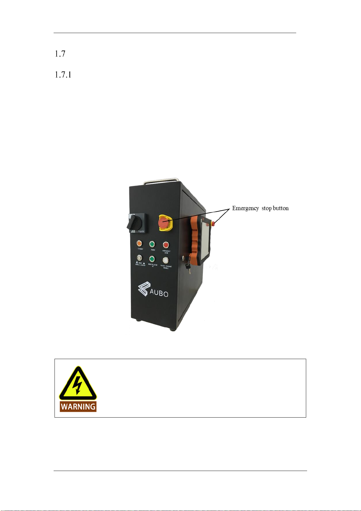
Emergency stop button can be found on the teach pendant and the control box of AUBO-i10. The
button must be pressed when a dangerous situation or emergency occurs. As shown in Figure1.1,
control box is equipped with an external port for emergency stop button. Integrators and users can
use according to the actual situation.
Figure 1-1 Emergency stop button
If the equipment or tools which connect to the end cause potential danger, it must
integrate to the emergency stop circuit in system. It may result in death, serious
injury or substantial property damage if failure to observe this warning notices
Page 24
V4.5
©2015-2019 AUBO.All rights reserved. 20
Recovering from the emergency condition
All the button type emergency stop device has a "lock" function. This "lock" must be opened to
end the emergency stop state.
Rotating emergency stop button can open the "lock".
Recovery from an emergency stop state is a simple but very important step. This
step can only operate after making sure that the robot system is completely
excluded from danger.
Emergency move for joint
In rare cases, it may be required to move one or more robot joints when the robot's power failure
or in an emergency, which can force the robot to move by follow method:
Forced back-driving: Force a joint to move by pulling hard (at least 700 N) on the robot arm.
Excessive force protection
Manipulator has excessive force protection. When manipulator is power-on and in stationary state,
if impact force hit by operators or other objects mistakenly exceeds the safety threshold, manipulator
will follow the direction of impact force to move passively. This function can reduce the damage
when operators or other objects collide with manipulator.
This function can reduce the collision damage and required to perform risk
assessment if other use is needed.
Forced to move the robot arm manually is limited to emergency situations and it
may damage the joints.
Page 25
V4.5
©2015-2019 AUBO.All rights reserved. 21
2. TRANSPORTATION AND PRECAUTIONS
When hoisting robot, the moving parts should be located properly to avoid unexpected movement
which can cause damage during hoisting and transportation. When packaging and transporting, it
should follow packaging standards and mark with the required signs outside the package.
When transporting, the robot must remain in its transport position stably.
The control box should be lifted using handle.
When moving robot from packaging to installation position, hold the robot in place until all
mounting bolts are safely tightened at the base of the robot.
Power up the robot after fixing it. Using hand-guiding to adjust robot orientation to a suitable
location.
Save the original packaging after transportation. Store the packaging material in a dry place for
future repackaging and moving the robot.
Users can move the manipulator to the installation position by using the packagePos project in the
【Online Programming】-> 【Project】-> 【Open Project】on the AUBOPE Programming
Environment. For details, please refer to 【Open Project】.(image demonstration)
1. Make sure not to overload the robot’s back or other body parts when the
equipment is lifted.
2. All regional and national guidelines should be followed. AUBO (Beijing)
Robotics Technology Co., Ltd is not responsible for any damage caused
during the transportation of equipment.
3. Make sure to follow the instruction when installing a robot.
Page 26

V4.5
©2015-2019 AUBO.All rights reserved. 22
Page 27
V4.5
©2015-2019 AUBO.All rights reserved. 23
3. MAINTENANCE, REPAIR AND DISPOSAL
Maintenance and repair
Maintenance and repair work must strictly follow all safety instructions in this manual.
Maintenance, calibration and repair work must be performed in accordance with the latest versions
of Service Manuals, which can be found on the support website www.aubo-robotics.com
All dealers in AUBO (Beijing) Robotics Technology Co., Ltd. should have the access to this
website.
Maintenance must be performed by authorized integrators or AUBO (Beijing) Robotics
Technology Co., Ltd. All parts returned to AUBO (Beijing) Robotics Technology Co., Ltd. will be
returned according to the service manual.
Make sure to reach the safety level of maintenance and repair, follow all regional and national
guidelines and test whether all safety functions work normally.
The purpose of maintenance and repair is to r to make sure that system runs normally or help it
return to normal condition when system error occurs, including faults diagnosis and actual
maintenance.
Operating manipulator or control box must follow safety procedures and warnings as below:
1. Remove the main input cable from the bottom of the control box to ensure
that it is completely power off. Take necessary precautions to prevent other
people from recharging the system during the repair period. After the
power is turned off, the system must be re-examined to ensure that is
powered off.
2. Please check the ground connection before turning the system back on.
3. Observe ESD (Electro-Static discharge) regulations when parts of the
manipulator or control box are disassembled.
4. Avoid disassembling the power supplies inside the control box. High
voltages can be present inside these power supplies for several hours after
the control box has been switched off.
5. Prevent water and dust entering the manipulator or control box.
Page 28
V4.5
©2015-2019 AUBO.All rights reserved. 24
1. Replace the defective components by new components with the same article
number or equivalent components approved by AUBO (Beijing) Robotics
Technology Co., Ltd.
2. Reactivate any deactivated safety measures immediately after the work is
completed.
3. Record all maintenance operations and save in technical documentation.
4. There is no self-serviceable part in control box. If maintaining or repairing
service is required, please contact your dealer or AUBO (Beijing) Robotics
Technology Co., Ltd.
Disposal
AUBO robot must be disposed in accordance with the applicable national laws, regulations and,
standards.
Page 29

V4.5
©2015-2019 AUBO.All rights reserved. 25
4. WARRANTIES
Product Warranty
AUBO robots have the finite warranty period for 12 months.
In the case of new devices and their components exhibiting defects resulting from manufacturing and/or
material faults within 12 months of entry into service (maximum of 15 months from shipment), AUBO
(Beijing) Robotics Technology Co., Ltd. should provide the necessary reserve components to replace or
repair the related components.
AUBO (Beijing) Robotics Technology Co., Ltd. has the ownership of the devices or components which have
been replaced or returned to AUBO (Beijing) Robotics Technology Co., Ltd.
If the products are no longer under warranty, AUBO (Beijing) Robotics Technology Co., Ltd. reserves the
right to charge customers for replacing or repairing the products.
If there are any defects appear in the device outside the warranty period, AUBO (Beijing) Robotics
Technology Co., Ltd. is not responsible for any damage or loss caused by the equipment, such as loss of
production or damage to other production equipment.
Disclaimer
1. This Warranty will be invalid if the equipment defect is caused by improper handling or failure to follow
the relevant information described in the user manual.
2. Failures caused by the following conditions are not covered by this warranty:
3. Does not meet the requirements of industrial standards or not following the user manual to install,
connect wires and connect to other control devices.
4. Using products beyond the specifications or standards of the manual.
5. Using products beyond the appointed purposes
6. Storage method and working environment are beyond the appointed range (e.g. pollution, salt injury
and moisture condensation).
7. Products’ damages caused by improper transportation.
8. Damage caused by accident or crash.
9. Not installing the original assembled components and accessories.
10. The damage caused by the third-party which is not AUBO (Beijing) Robotics Technology Co., Ltd. or
the designated integrator while reconstructing, adjusting or repairing the original components.
11. Any nature disasters including fires, earthquakes, tsunamis, lightning, high winds and flooding.
12. Any malfunction not relates to AUBO (Beijing) Robotics Technology Co., Ltd.’s responsibility apart
from the circumstances mentioned above.
Page 30

V4.5
©2015-2019 AUBO.All rights reserved. 26
Warranty will not be provided in following circumstances:
1. Unable to identify the production date or the warranty start date.
2. Changing the software or the internal data.
3. The malfunction cannot reappear or be identified by AUBO (Beijing) Robotics Technology Co., Ltd.
4. Using the products as radioactive equipment, biological test equipment or any other dangerous
environment ascertained by AUBO (Beijing) Robotics Technology Co., Ltd.
According to the product warranty, AUBO (Beijing) Robotics Technology Co., Ltd. only provides warranty
to the flaws and defects in the products and components which are sold to dealers.
AUBO (Beijing) Robotics Technology Co., Ltd. is not responsible for the relevant warranty responsibility
to any other express or implied warranty or responsibility, including but not limited to the implied warranty
to the merchantability or the specific use. In addition, AUBO (Beijing) Robotics Technology Co., Ltd. is not
responsible for any indirect damage and consequences caused by the relevant products.
Page 31
V4.5
©2015-2019 AUBO.All rights reserved. 27
5. ROBOT HARDWARE COMPOSITION
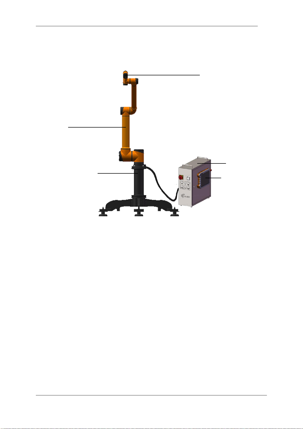
Figure 5-1 AUBO-i10 robot
As shown in figure 5.1, The AUBO-i10 robot system consist of a manipulator, a control box(which can
choose a variety of models), a manipulator base and a teach pendant. The manipulator imitates human which
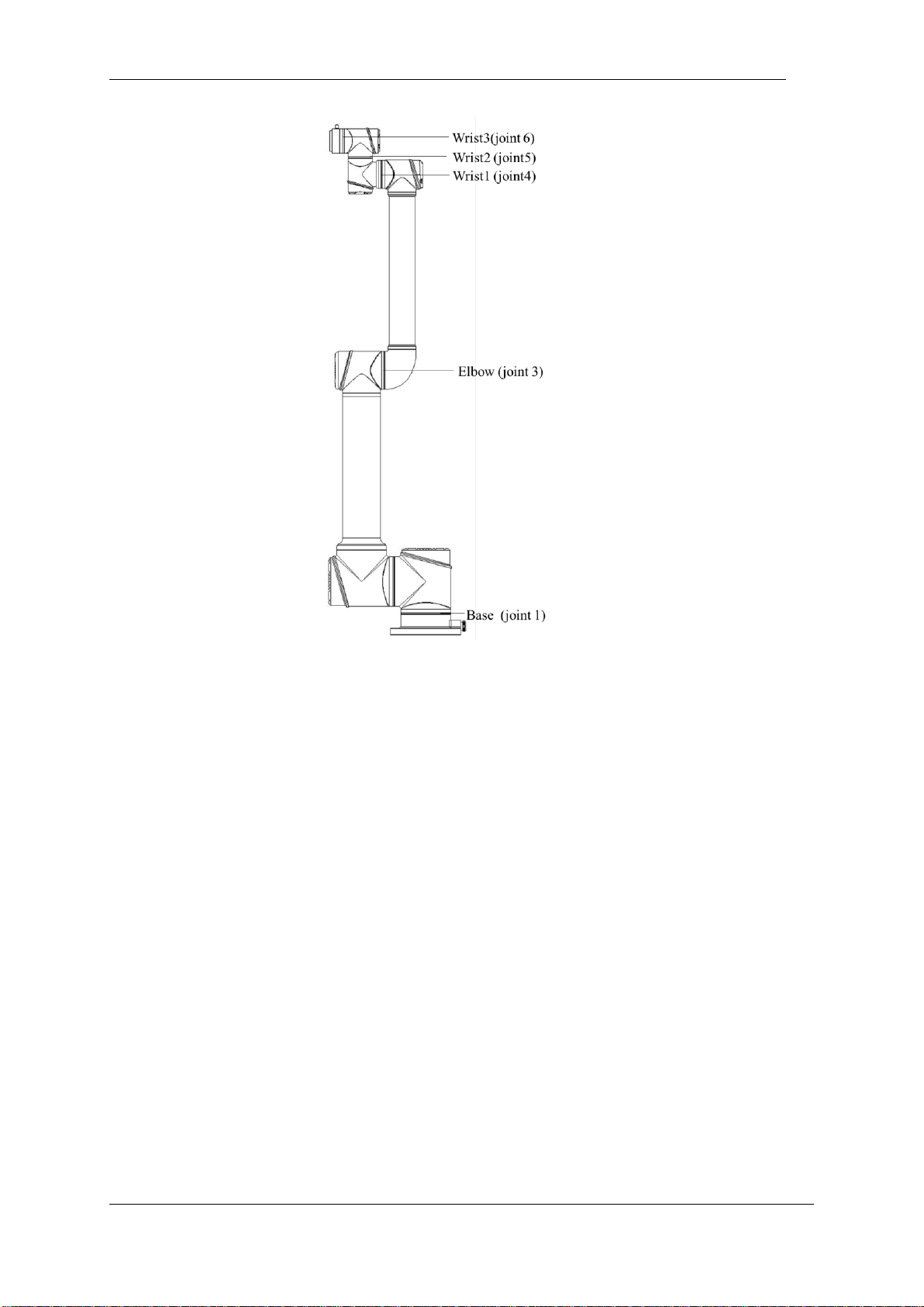
has six joints and each joint represents a degree of freedom. As shown in figure5.2, manipulator’s joint
includes a robot base (A), a shoulder (B), an elbow (C), a wrist1(D) ,a wrist2(E) and a wrist3(F). The
manipulator base is used for the robot body and the base connection. End-effector is used to connect
manipulator and tool. Aluminium pipe is used to connect shoulder and elbow or elbow and wrist. Through
the AUBOPE user interface or hand-guiding, users can control the rotation of every joint and move endeffector to any poses.
Manipulator
Manipulator base
Control box
Teach pendant
Flange
Page 32
V4.5
©2015-2019 AUBO.All rights reserved. 28
Figure 5-2 -1 Manipualtor Joints
Control box is the main control part of AUBO-i10 robot. Please read chapter 8 for any modules inside control
box.
AUBO-i10 provides multiple I/O interfaces, there are 4-channel digital I/O and 2-channel analog inputs on
end-effector flange. Control box communicates with manipulator by CAN-Bus.
The teach pendant provides a visual interface. Users can test, program, and simulate the manipulator through
the teach pendant with a small amount of programming skills.
Page 33
V4.5
©2015-2019 AUBO.All rights reserved. 29
6. ROBOT INSTALLATION
Brief installation steps
The installation of AUBO robots includes:
1. Define a robot workspace;
2. Install the robot manipulator on base;
3. Install end-effector
Important safety instructions
Installation Conditions:
•No corrosive gases or liquids •No oil mist
•No salt •No dust or metal powders
•No mechanical shock, vibration •No electromagnetic noise
•No radioactive materials •Low humidity
•No flammable materials
•Ambient temperature:0°C ~ 45°C
•Avoid direct sunlight (avoid using outdoor)
Floor carrying capacity:
Install manipulator on a hard surface which can undertake at least 10 times
heavier than overturning moment of robot base and at least 5 times the weight of
the manipulator. Moreover, the surface cannot be shaken. Please read appendix
for more precise data of carrying capacity.
Safety assessment is needed after every installation. Please strictly follow the
instructions in chapter 1(Safety).
Page 34

V4.5
©2015-2019 AUBO.All rights reserved. 30
Install additional equipment:
If any additional modules, like cable, which are not provided by AUBO (Beijing)
Robotics Technology Co., Ltd., are integrated in industrial robot, users have the
responsibility to ensure these modules won’t affect safety function.
1. Safety assessment must be performed each time the robot is installed, and
the instructions in Section 1 (Safety) are strictly observed.
2. The control box should be placed horizontally on the ground. A 50 mm
gap should be reserved on each side of the control box to ensure smooth
air circulation
3. The teach pendant can be hung from the control box. Make sure you don't
step on the cable.
1. Make sure that the control box, teach pendant, and cable are not exposed
to liquids. A wet control box can cause casualties.
2. The control box and teach pendant should not be exposed to dust or
moisture in an IP54 class. Pay close attention to the environment where
conductive dust is present.
Workspace of the Robot
Mechanical dimensions of manipulator
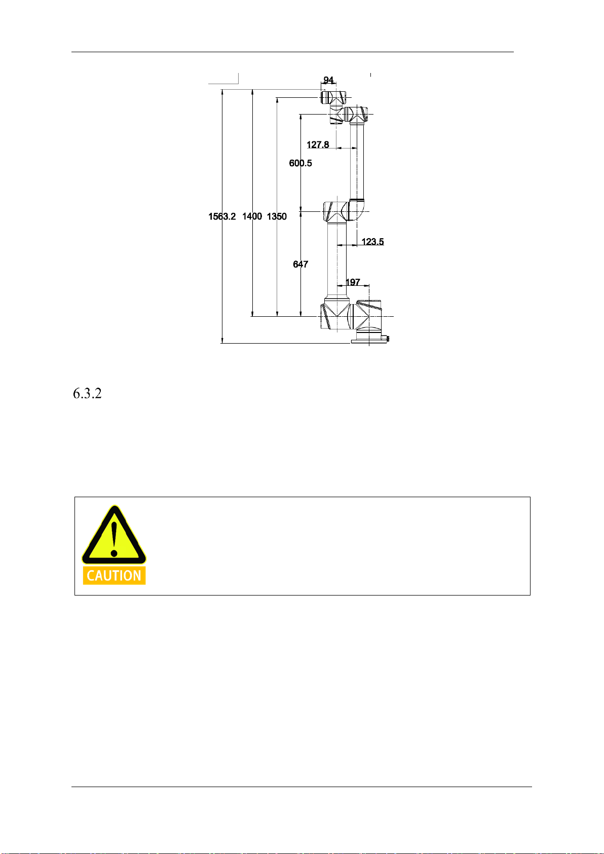
The mechanical dimensions of the manipulator are shown in figure 6.1. The robot working range should be
firstly considered during installation in case of bumping into people or equipments around.
Page 35
V4.5
©2015-2019 AUBO.All rights reserved. 31
Figure 6-1 AUBO-i10 mechanical dimensions, unit: mm
Effective working range
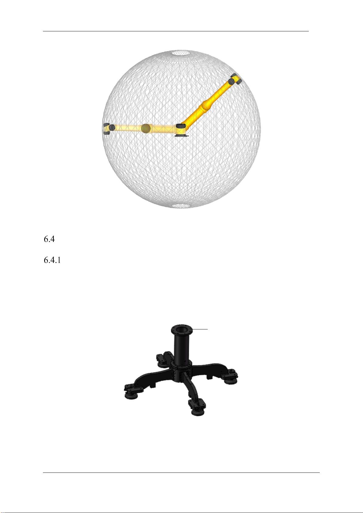
The workspace of the manipulator, as shownin Figure 6.2, is a sphere of radius 1350mm except the
cylindrical space directly above and directly below the robot base. When choosing the installation position,
be sure to consider the cylindrical space directly above and directly below the robot base must to avoid
moving the tool into this cylindrical space as much as possible. In practical application, the range of
rotationa of joint 1 to joint 6 is -175°~ +175°.
The robot must work within an effective workspace.
Page 36
V4.5
©2015-2019 AUBO.All rights reserved. 32
Figure 6-2 AUBO-i10 workspace illustration
Hardware Installation
The Manipulator Base
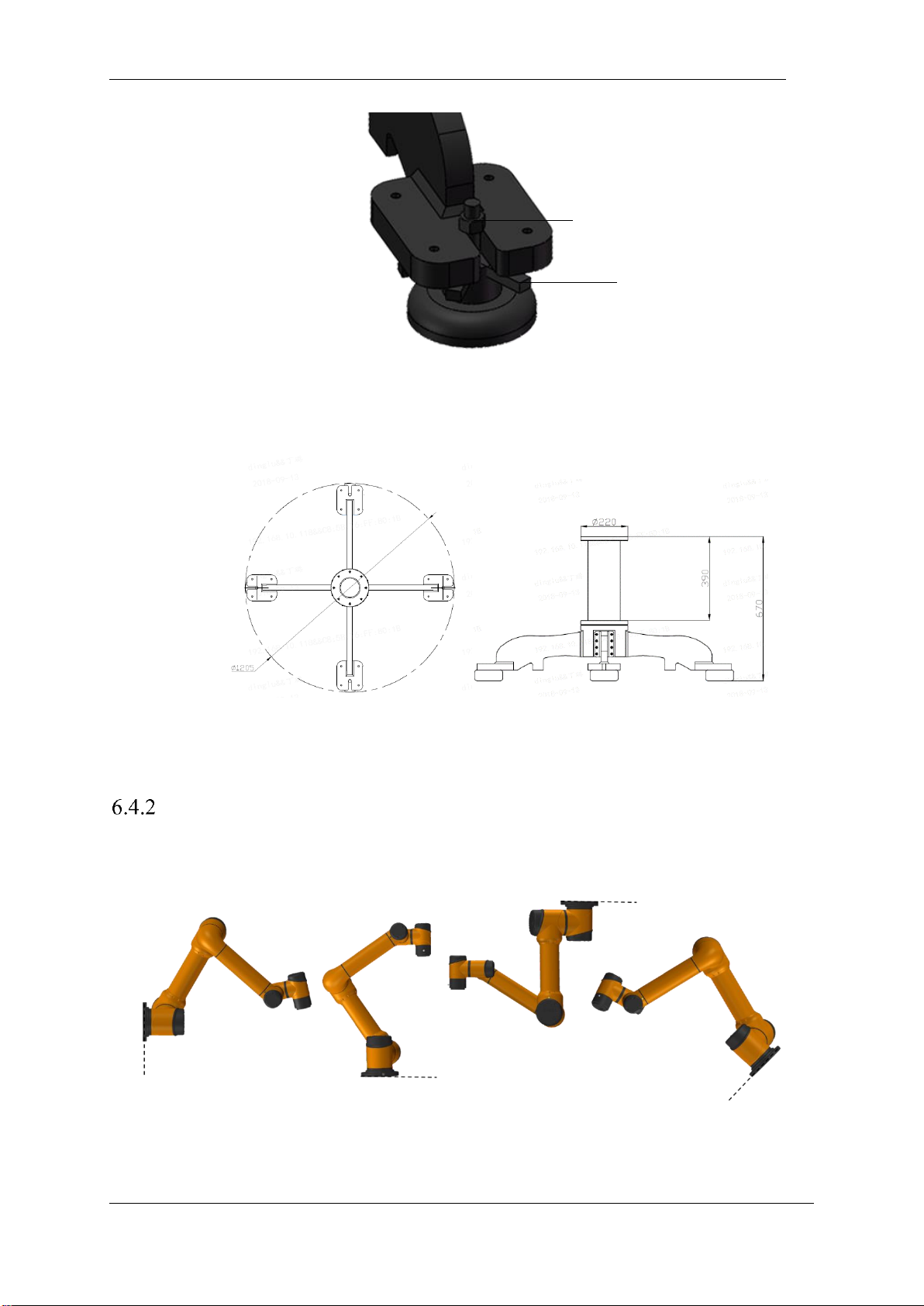
AUBO robot manipulator base is shown in figure 6.3.
The base has 4 anchor bolts for easy fixing. When the user needs to fix the robot, rotate the plum wheel to
adjust the height of the anchor bolt, and tighten the nut to fix the robot. It is recommended to use a live
wrench to rotate the nut.
Base and robot contact surface
Page 37
V4.5
©2015-2019 AUBO.All rights reserved. 33
Figure 6-3 Diagram of manipulator base structure
The mechanical dimensions of the manipulator base structure are shown in Figure 6.4
Figure 6-4 Mechanical dimensions of the manipulator base structure (left: plan view; right: front view)
Manipulator Installation
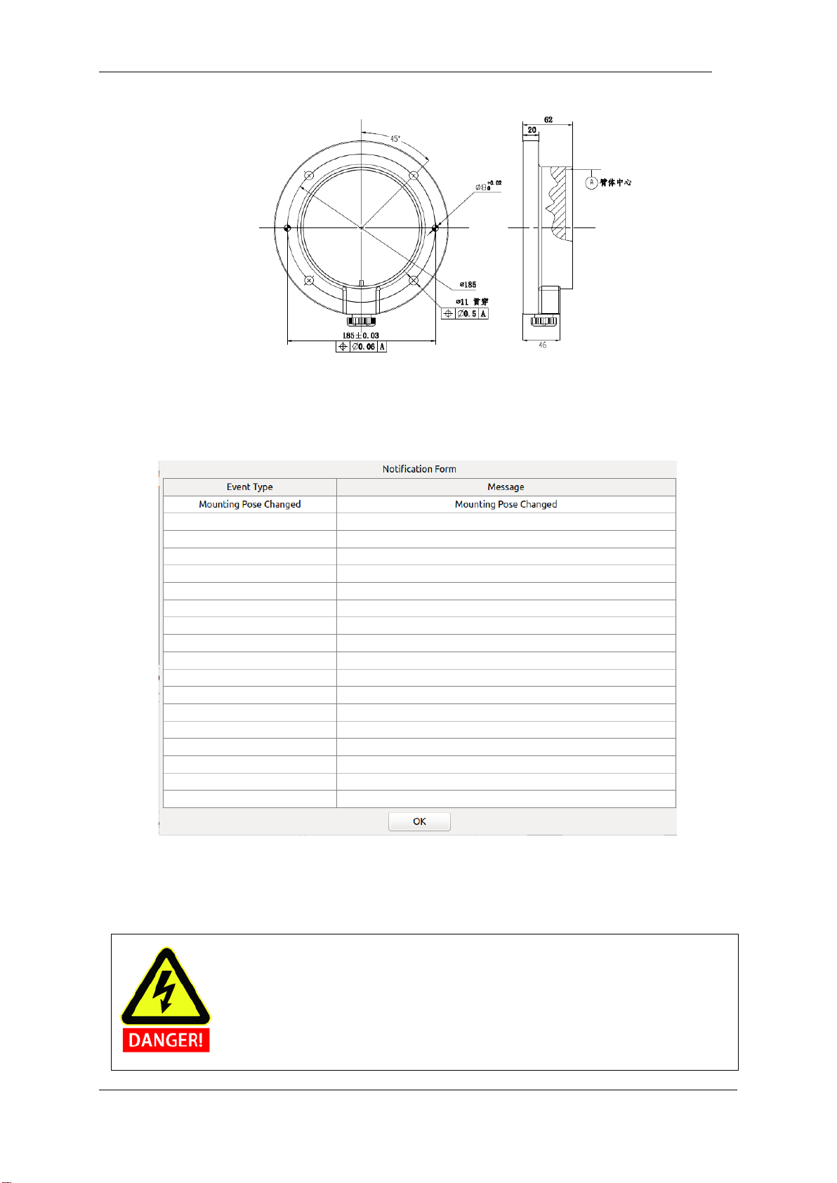
The robot has a function of self-adaption for Installation pose. It can be installed in base, hoisting, mount on
wall or any specific installation method, as shown below:
Figure 6-5 Diagram of different installation poses
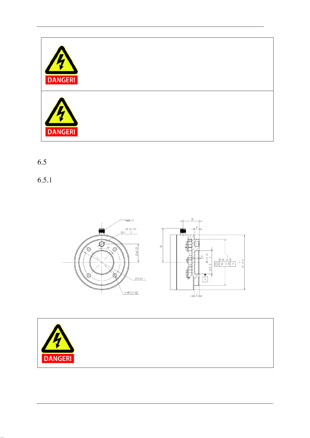
Using four M8 bolts to fix manipulator on the base. It’s recommend using two -6mm holes to install pins
to improve the installation accuracy. Mechanical dimensions is shown in Figure 6.6.
Nut
Plum blossom wheel
Page 38
V4.5
©2015-2019 AUBO.All rights reserved. 34
Figure 6-6 : Mounting whole size of the manipulator base.
If installation method is changed (such as choosing hoisting, wall-mounted etc.), after running the AUBOPE
and click the “ON” ->” OFF”, then the teach pendant will pop up following window:
Figure 6-7 Pop window of changing installation position
Under this circumstance, please choose the correct option on the AUBOPE, otherwise, it may have
unpredictable movement in hand-guiding mode.
Make sure manipulator is installed correctly and safely
Page 39
V4.5
©2015-2019 AUBO.All rights reserved. 35
If the robot is submerged in water over an extended time, it might be damaged. The robot
should not be installed in water or in a wet environment unless it has IP67 protection class.
Tipping hazard. If the robot is not safely placed on a soild surface, the robot can fall over
and cause injury.
End-effector Installation
Mechanical structure size of end-effector flange
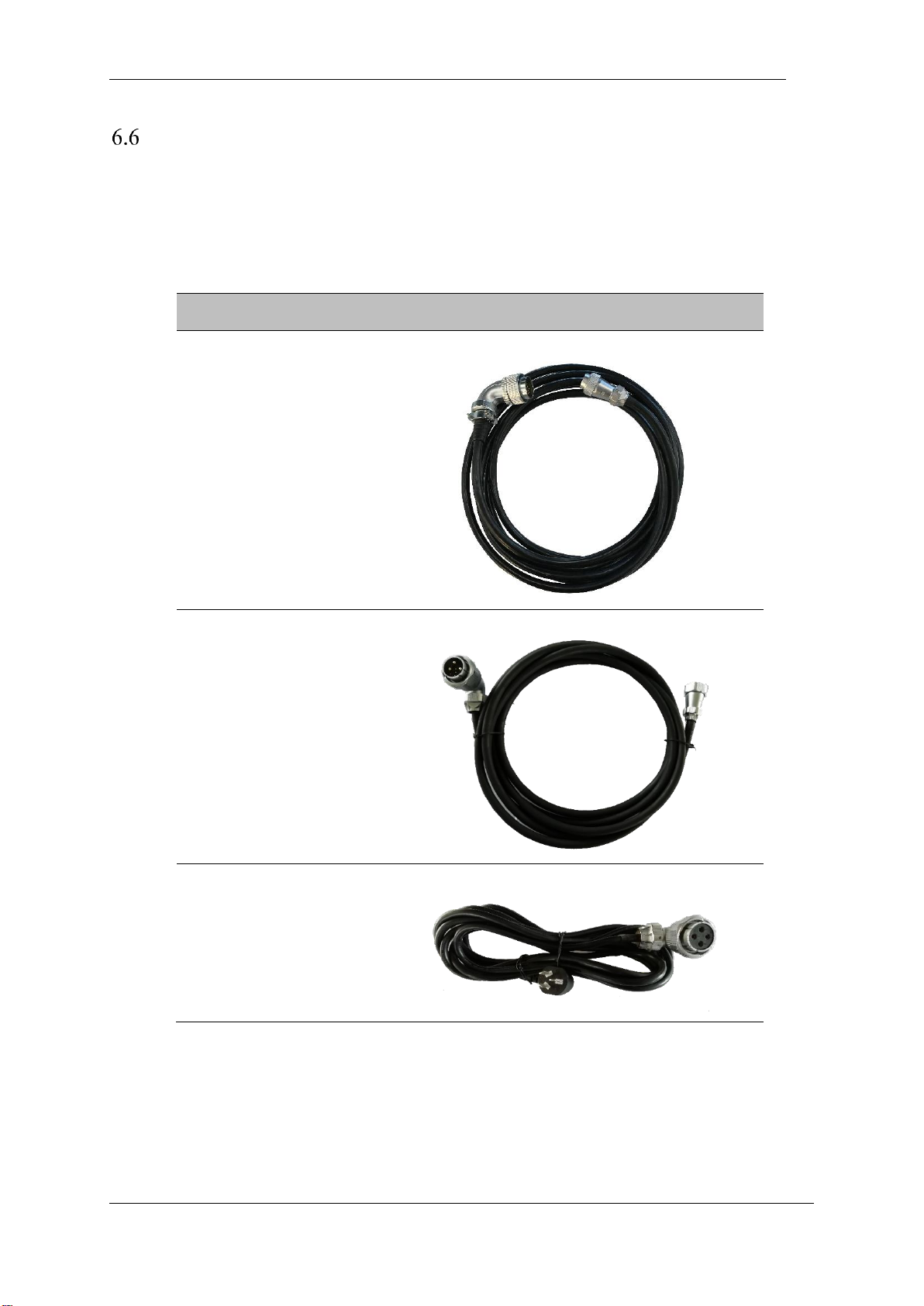
End-effector flange has four M6 threaded holes and a Ф6 positioning hole to fix the fixture on the end
easily, as shown in figure 6.8.
Figure 6-8 Mechanical dimensions of end-effector flange, unit: mm.
1. Make sure the tool is properly and safely bolted in place.
2. Make sure that the tool is constructed such that it cannot create a hazardous situation by
dropping a part unexpectedly.
Page 40
V4.5
©2015-2019 AUBO.All rights reserved. 36
Cable connection
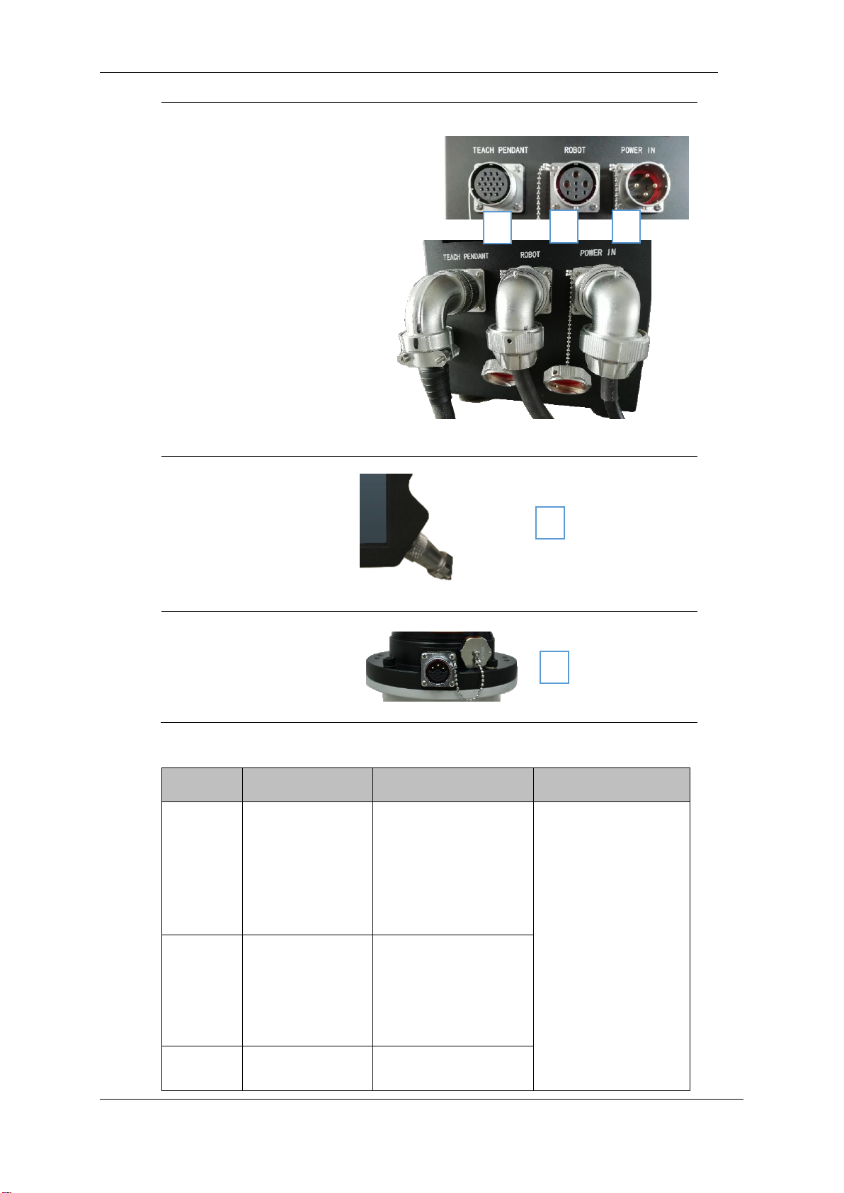
There are 3 sockets on the bottom of the control box. There is a socket on the bottom of the robot body.
There is a socket on the lower right side of the teach pendant. Insert the corresponding cable into the socket
before use.
Table 3 Cable Connection Diagram
Classification
Photo
Teach pendant cable
Manipulator cable
Control box power cable
Page 41
V4.5
©2015-2019 AUBO.All rights reserved. 37
Socket at the bottom of the
control box that is connected
to the cable
Teach pendant cable
connected to the teach
pendant
Manipulator cable connected
to the manipulator
Table 4 Cable Connection Method
Number
Classification
Description
Connection method
1
Teach pendant
cable connected to
control box
One end of the teach
pendant cable
connected to the control
box is a curved circular
aviation plug.
First unscrew the dust
cap on the control box
interface from the
socket, and then insert
the elbow round
aviation plug into the
control box. Pay
attention to the
direction of insertion
and tighten the locking
ring after inserting it.
2
manipulator cable
connected to the
control box
The end of the robot
cable connected to the
control box is a curved
circular aviation plug.
3
External power
The end of the external
1
2
3
4
5
Page 42

V4.5
©2015-2019 AUBO.All rights reserved. 38
cable connected to
the control box
power cable cable that
connects to the control
box is a curved round
aviation plug.
4
Teach pendant
cable connected to
the teach pendant
One end of the teach
pendant cable
connected to the teach
pendant is a straight
tube aviation plug.
First unscrew the dust
cap on the teach
pendant interface from
the teach pendant and
insert the straight air
plug into the teach
pendant. Pay attention
to the direction of
insertion and tighten
the locking ring after
inserting it.
5
Robot cable is
connected to the
robot body
One end of the robot
body cable connected to
the robot body is a
straight pipe aviation
plug.
First unscrew the dust
cap on the robot body
interface from the
socket; align the pins
of the plug and the
socket with the socket
respectively. The
judgment mark is
whether the gap on the
socket and the
protrusion on the plug
are aligned, and then
insert the plug. In the
socket; rotate the
fastening nut on the
plug clockwise (in the
direction of the plug
toward the socket) until
you hear a 'click',
indicating that the
connection is
successful.
Pay attention to the following when connecting cables
Page 43
V4.5
©2015-2019 AUBO.All rights reserved. 39
1. Make sure the robot is grounded (electrical ground) in the correct
way. The grounding connector should have at least the rated
current of the highest current in the system.
2. Make sure that all cables are properly connected before the
control box is energized. Always use the original power cord
correctly.
3. Never disconnect the robot cable while the robot arm is open.
4. Do not extend or modify the original cable.
Page 44

V4.5
©2015-2019 AUBO.All rights reserved. 40
Page 45
V4.5
©2015-2019 AUBO.All rights reserved. 41
7. THE I SERIES STANDARD CONTROL BOX
Introduction
Control box is the control center of AUBO robot, which contains a control board, a safety control board, a
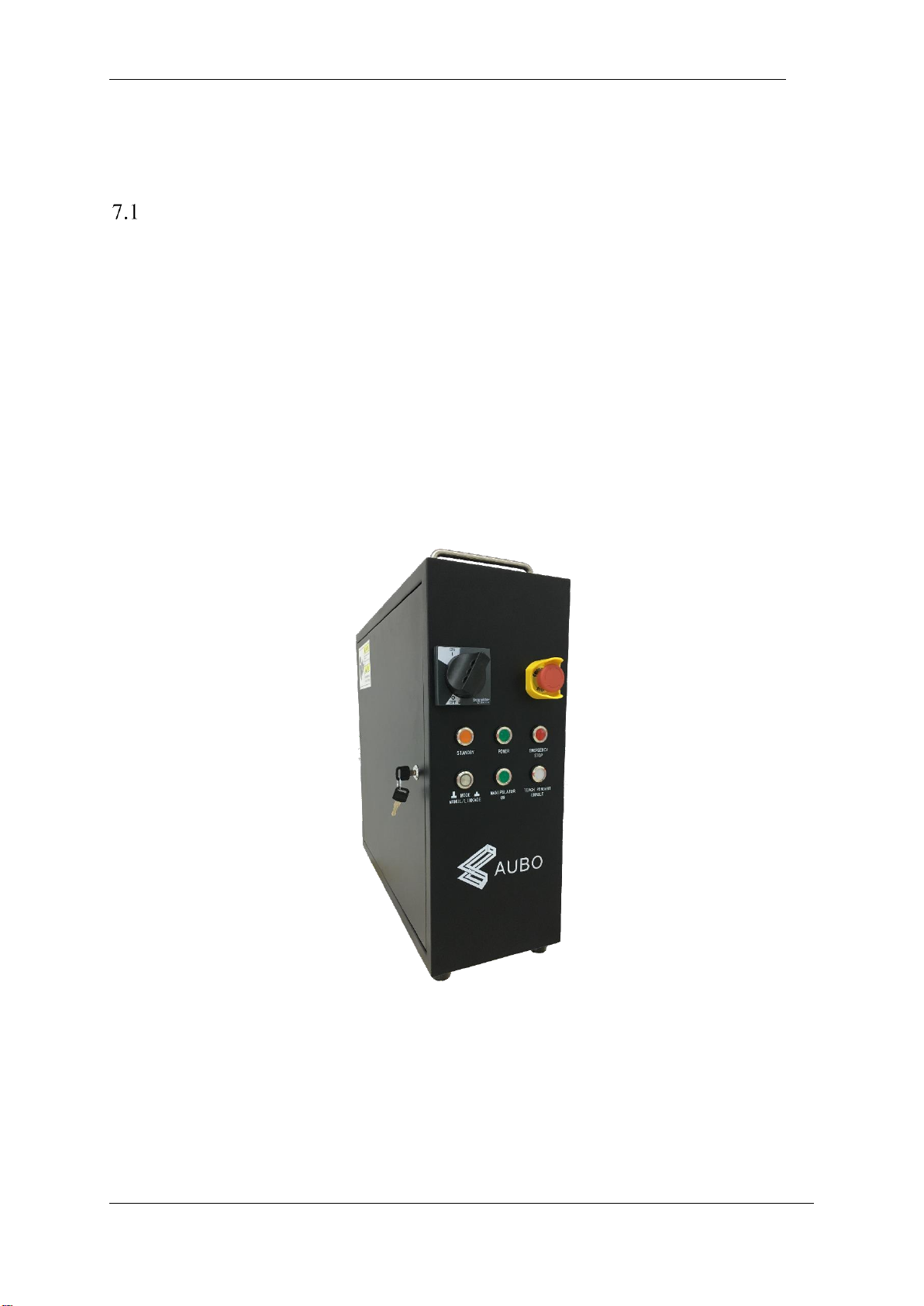
switching power supply and a safety protection device. The control box is powered by 100V-240V AC. Its
2 internal switching power supplies convert 100V-240V AC into 12V, 24V and 48V DC which supply
power for the load inside control box and the robot. Therefore, the connection between the robot and the
teach pendant or the control box must be checked securely before use.
Control box is designed with hardware protection and software protection to ensure the security in the
greatest degree when people use. Using multiple circuit breakers inside the control box plays a reliable role
in short-circuit and overload protection on the hardware. With the emergency stop button in both the
control box and the teach pendant, users can cut off robot’s power in the shortest time to protect personnel
and equipment.
Figure 7-1 I Series Standard control box
Page 46
V4.5
©2015-2019 AUBO.All rights reserved. 42
Electrical warnings and cautions
The following warnings and cautions must be observed when a robot and control box application is
designed and installed. The warnings and cautions also apply for service work.
Never connect safety signals to a PLC which does not fulfill the requirements of a
correct safety level. Failure to follow this warning could result in serious injury or
death due to the failure of the safety stop function
1. Make sure that all non-waterproof equipment remains dry. If water comes inside the
product, turn off all the power switches and then contact your supplier.
2. Use original cables supplied with the robot only. Do not use the robot for
applications where the cables will be subjected to bent. Contact your supplier if
longer or flexible cables are needed.
3. All mentioned GND connections are only for powering and transimitting signals.
For Protective Earth (PE) use the screw connections marked with the earth symbols
inside the control box. The grounding conductor shall have at least the current rating
of the highest current in the system.
4. Be careful when installing the interface cables to the robot’s I/O.
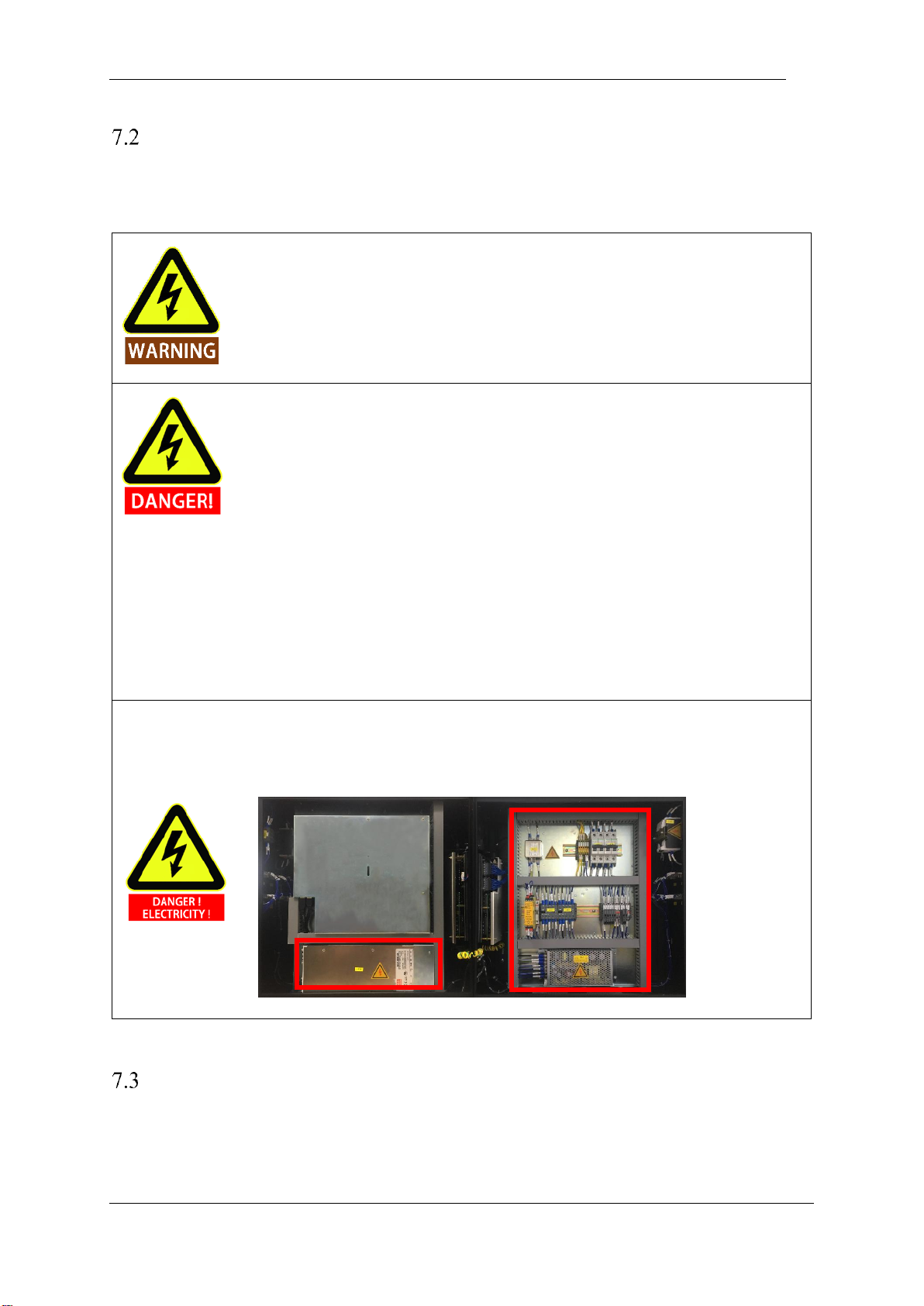
As shown in the figure below, the red frame area is AC 100-240V and DC 48V
hazardous area. Do not touch the fastening screws and other metal parts directly by
hand. Do not remove the wiring by power.
Control box panel introduction
The front panel, side panel and back panel of the control box are related to switches, buttons, indicators and
electrical interfaces.
Page 47
V4.5
©2015-2019 AUBO.All rights reserved. 43
Control box front panel
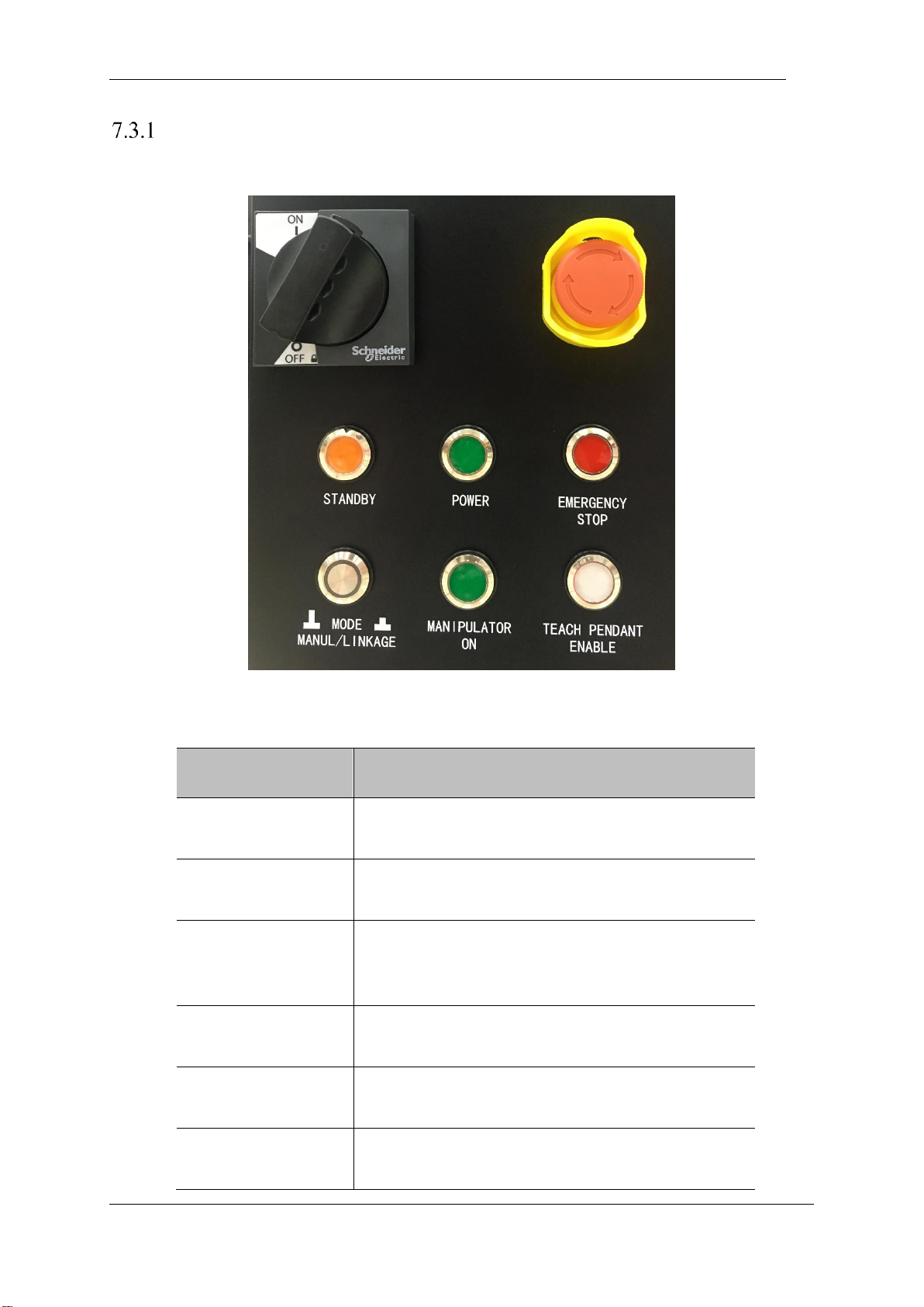
The front panel structure of the control box is shown below.
Figure 7-2 Schematic diagram of the front panel of the control box
Table 5 Front panel switch, button and indicator function description
Name
Function
POWER SWITCH
The main power switch, 1 is the power-on state, and 0 is the
power-off state.
EMERGENCY
The robot emergency stop button, the robot is powered off
after pressing.
STANDBY
When the indicator light is on, it indicates that the control
panel interface board program is initialized. You can press
the teach pendant power button to power on the robot.
POWER
The indicator light is on to indicate that the external power is
on.
EMERGENCY STOP
The indicator light indicates that the robot is in an emergency
stop state.
MODE
MANUAL/LINKAGE
Robot manual mode and linkage mode selection. When the
button is pressed, the robot enters the linkage mode.
Page 48
V4.5
©2015-2019 AUBO.All rights reserved. 44
MANIPULATOR ON
When pressed, the robot power is turned on, and the indicator
light indicates that the robot is powered on.
TEACH PENDANT
The teach pendant enable status display. In manual mode, the
indicator light is always on. In the linkage mode, the
indicator light is off to indicate that the teach pendant is not
available.
Control box side panel
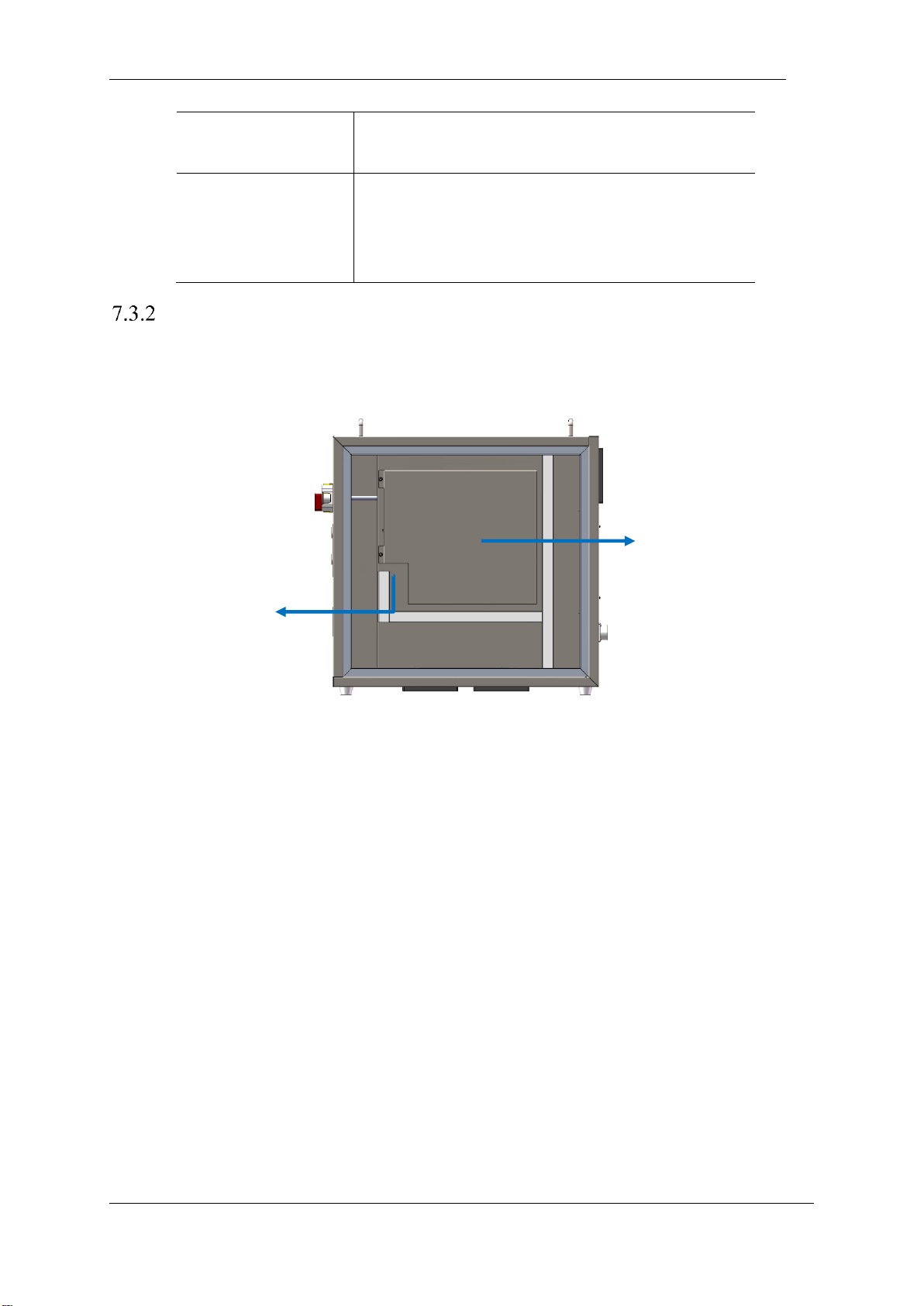
The USB interface is provided on the right side of the control box. Users can open the control box side door
by rotating the key to use this interface.
Figure 7-3 USB communication interface on the side of the control box
USB interfacce
Shield protection
Page 49
V4.5
©2015-2019 AUBO.All rights reserved. 45
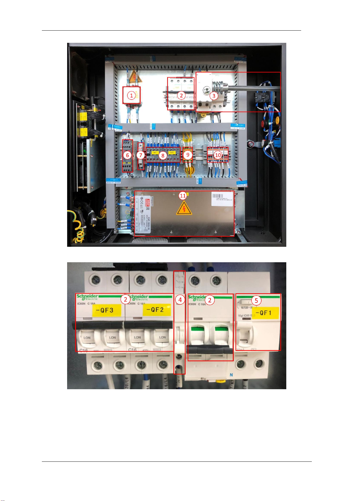
Figure 7-4 Control box side panel parts marking a
Figure 7-5 Control box side panel parts marking b
Page 50
V4.5
©2015-2019 AUBO.All rights reserved. 46
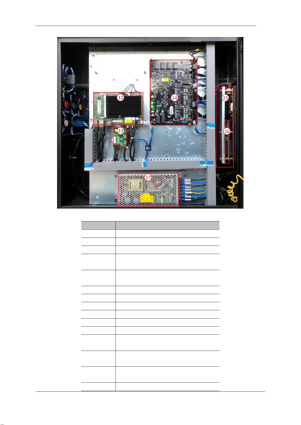
Figure 7-6 Control box side panel parts marking c
Number
Name
1
filter
2
breaker
3
Power on handle
4
Status indicator module (can be displayed after
removing the 3 power-on handle)
5
Leakage protector (displayed after removing the
3 power-on handle)
6
Safety Relays
7
Teachee enable switch
8
AC contactor
9
Ground terminal
10
Sub-terminal
11
48V DC power supply
12
Motherboard (displayed after removing the
shield cover)
13
VGA differential board (displayed after
removing the shield cover)
14
Main control interface board (can be displayed
after removing the shield protection cover)
15
User IO board
Page 51
V4.5
©2015-2019 AUBO.All rights reserved. 47
16
IO expansion board
17
24V/12V DC power supply
Control box back panel
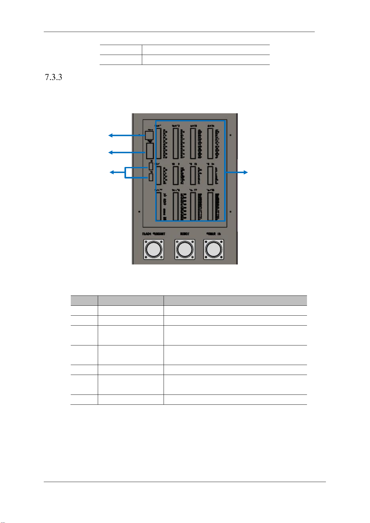
The Ethernet interface and USB interface are provided on the rear side of the control box. Two USB ports
are provided on the motherboard on the side of the control box. See the following figure.
Figure 7-7 Communication interface on the back of the control box
Table 6 Description of the control panel back panel interface
Number
Interface
Function
1
Ethernet interface
Can be used for remote access and control.
2
Modbus RTU interface
Can be connected to a Modbus device
3
USB interface
Can be used to update software, import and export
project files.
4
Electrical interface
outside the control box
Provide external I/O interface
5
Teacher cable interface
Connect the teach pendant cable
6
Robot body cable
interface
Connect the robot body cable
7
Power interface
Connect the power cord
USER I/O
Ethernet interface
USB interface
Modbus RTU
Page 52
V4.5
©2015-2019 AUBO.All rights reserved. 48
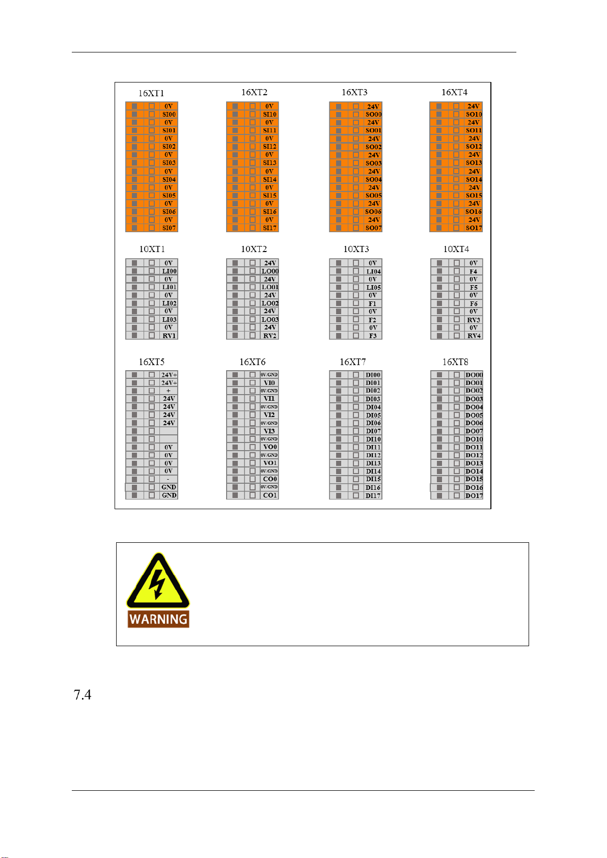
Figure 7-8 Schematic diagram of the external electrical interface of the control box
It is forbidden to plug and unplug the USB device while the robot is
running.
Selection of working mode
The robot system has two working modes, manual and linkage, which are selected by button switches. When
changing the working mode of the robot system, it is necessary to select the specified working mode after
power off, and then re-inspire the teaching device and the robot body.
Page 53
V4.5
©2015-2019 AUBO.All rights reserved. 49
Manual mode
In the manual mode, the signal that is externally fed into the arm through the interlock mode IO cannot
control the arm. This mode is generally suitable for working conditions with only one robot arm.
➢ Power on: Turn on the main control switch of the control box and wait until the standby indicator
lights up. Press the teach pendant start button for about 1 second and the robot powers up.
➢ Force control button: When the robot is in the teaching mode, press and hold the teach pendant force
control button to the middle gear position, drag the robot to the target position, and release the button.
➢ Emergency stop: Press the emergency stop button on the teach pendant or control box to power off the
robot. Rotate the emergency stop button, follow the instruction of the teach pendant interface to
operate the teach pendant, and the arm is powered back on.
➢ Shutdown: Normal exit: Press the software close button in the upper right corner of the teach pendant
to exit the program; forcibly shut down: long press the start button in the upper left corner of the teach
pendant for about 3s, the blue light is off, the teach pendant and the robot are powered off.
Linkage mode
In the linkage mode, the robot arm can communicate with one or more external devices (mechanical arms,
etc.) through the linkage mode IO port. This mode is generally suitable for coordinated motion between
multiple robot arms.
Table 7 User linkage mode IO function and status description in linkage mode
Input
Interface board IO function and status
LI00
Program start signal input interface in linkage mode
LI01
In the linkage mode, the program stops the signal input interface.
LI02
In the linkage mode, the program pauses the signal input interface.
LI03
In the linkage mode, the program returns to the initial position signal
input interface.
LI04
Remote power-on signal input interface (can also be remotely controlled
in non-linked mode)
LI05
Remote shutdown signal input interface (can also be remotely controlled
in non-linked mode)
Output
Interface board IO function and status
LO00
Program operation signal output interface in linkage mode
LO01
Program linkage signal output interface in linkage mode
LO02
In the linkage mode, the program pauses the signal output interface.
LO03
In the linkage mode, the program returns to the initial position signal
output interface.
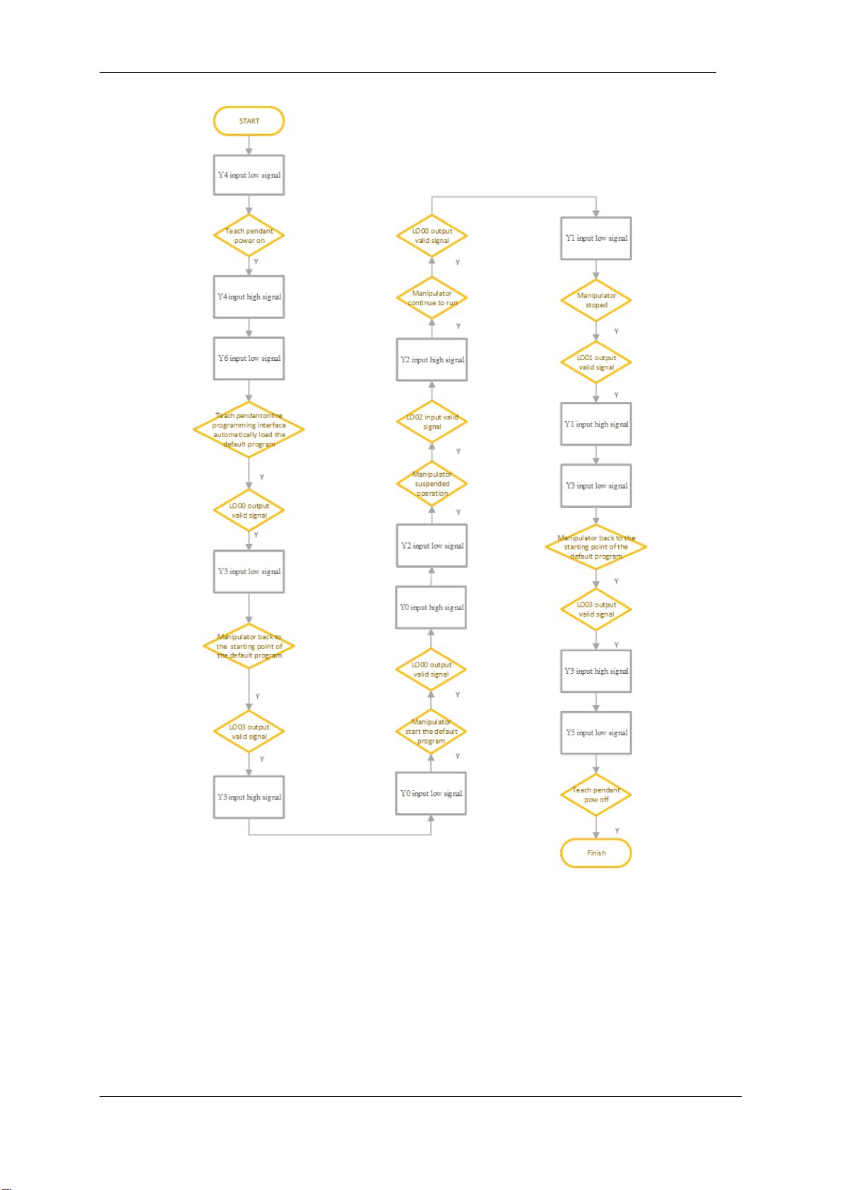
The case below demonstrates how to use external device to manuplate the robot under linkage mode. Users
can refer the process described below:
For the first-time use, the user needs to configure the default boot program in the teach pedant manually.
Instructions are below:
Page 54
V4.5
©2015-2019 AUBO.All rights reserved. 50
After the teach pendant is started, select the project file in the online programming -> project -> default
project and select the automatic loading of the default project and click OK to set the default project.
Make sure the power to the control box is disconnected.
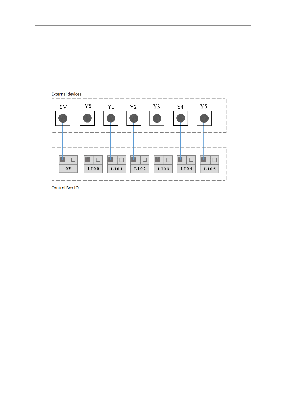
Follow the demonstration below, connect the external devices with IO interface on the back of the control
box. Users can use the external singals to manipulate the robot.
Figure 7-9 linkage mode wire connection showcase
Press the button “MODE MANUAL/LINKAGE” on the front panel of the control box.
Power the control box.
Configure the external devices singals.
Then the user can follow the process below to use linkage mode.
Page 55
V4.5
©2015-2019 AUBO.All rights reserved. 51
Figure 7-10 linkage mode use showcase
Under linkage mode, if the teach pendant is not needed, after setup the default program successfully, the user
can switch off the teach pendant enable in the control box. After “TEACH PENDANT ENABLE” is out, it
is ok to remove the wire from the teach pendant.
Page 56

V4.5
©2015-2019 AUBO.All rights reserved. 52
Page 57
V4.5
©2015-2019 AUBO.All rights reserved. 53
8. INTERNAL ELECTRICAL INTERFACE
Introduction
The AUBO robot I series standard control box provides a variety of electrical interfaces to connect the
external equipments and tools. Users can easily use these interfaces.
The electrical interface of the control box is divided into: safety I/O and general I/O. The AUBO interface
board has 16 general digital input interfaces, 16 general digital output interfaces, 4 pairs of analog voltage
input interfaces, 2 pairs of analog voltage output interfaces and 2 pairs of analog current output interface.
The electrical error is about ±1%.
IO Specification
All AUBO robot IOs are set to NPN mode, which means low voltage level effective. When an User IO is
set to “Effective” or “High” on the teach pendant, the actual voltage level at the IO output is low.
Note Open circuit protection is set in each IO. Therefore, whenever an IO is not connected in a closed
circuit, its output voltage is going to remain at high even if the IO is set to “Effective” by script or by teach
pendant.
For digital IO outputs, the method to check the IO status is to measure the resistance between DO and 0V.
When the DO is set to “Effective” or “High”, the resistance goes to approximately 0Ω, otherwise the
resistance is about 12KΩ.
Electrical warnings and cautions
The following warnings and cautions must be observed when a robot and control box application is
designed and installed. The warnings and cautions also apply for service work.
Never connect safety signals to a PLC which does not fulfill the requirements of a
correct safety level. Failure to follow this warning could result in serious injury or
death due to the failure of the safety stop function
1. Make sure that all non-waterproof equipment remains dry. If water comes inside the
product, turn off all the power switches and then contact your supplier.
2. Use original cables supplied with the robot only. Do not use the robot for
applications where the cables will be subjected to bent. Contact your supplier if
longer or flexible cables are needed.
3. All mentioned GND connections are only for powering and transimitting signals.
For Protective Earth (PE) use the screw connections marked with the earth symbols
inside the control box. The grounding conductor shall have at least the current rating
Page 58
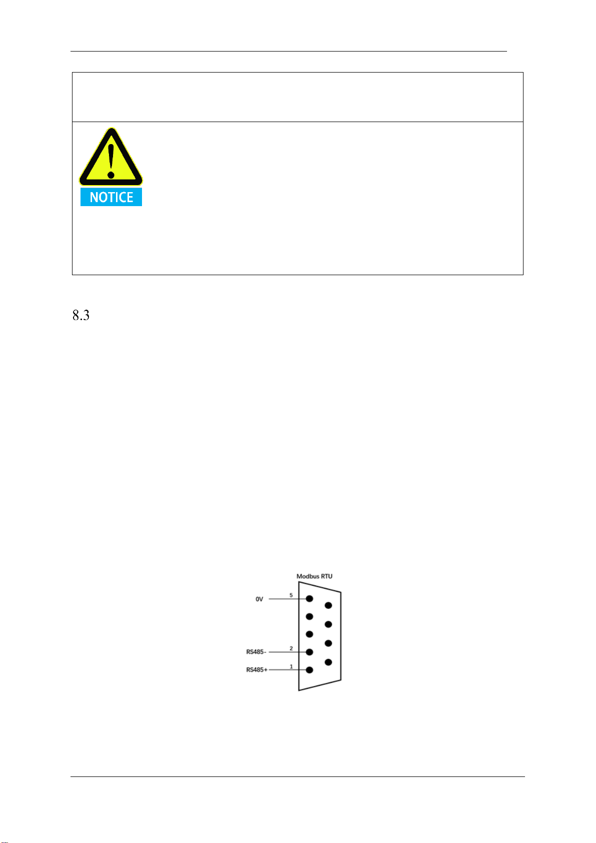
V4.5
©2015-2019 AUBO.All rights reserved. 54
of the highest current in the system.
4. Be careful when installing the interface cables to the robot’s I/O.
1. Interference signals higher than the level specified in the IEC standard will cause the
abnormal behavior of the robot. Extremely high signal levels or excessive exposure
can damage the robot permanently. EMC problems usually occur in welding
processes and are normally prompted by an error messages in the log. AUBO
(Beijing) Robotics Technology Co., Ltd is not responsible for the loss caused by the
EMC problem.
2. I/O cables going from the control box to other machinery and factory equipment
may not be longer than 30m, unless extended tests are performed.
Control box communication interface
The AUBO Robotic I Series standard control box provides a variety of electrical interfaces for connecting
external devices that are easily accessible to the user.
Remove the back cover of the back panel of the control box. The panel provides Ethernet interface, Modbus
RTU interface, USB interface and some electrical interfaces. (Refer to 7.3.3 Control box back panel)
Ethernet interface
The Ethernet interface can be used for remote access and control. Users can refer to 10.6.3 Network
Settings to connect external control devices.
Modbus device interface
The Modbus device interface is located on the back panel of the control box (see 7.3.3 Control Panel Back
Panel). Modbus devices can be connected via the USB interface and the Modbus RTU interface.
The Modbus RTU interface pin description is shown below:
Figure 8-1 Modbus pin description
USB interface
The USB interface is located on the back panel and side panel of the control box (see 7.3 Control box
Page 59
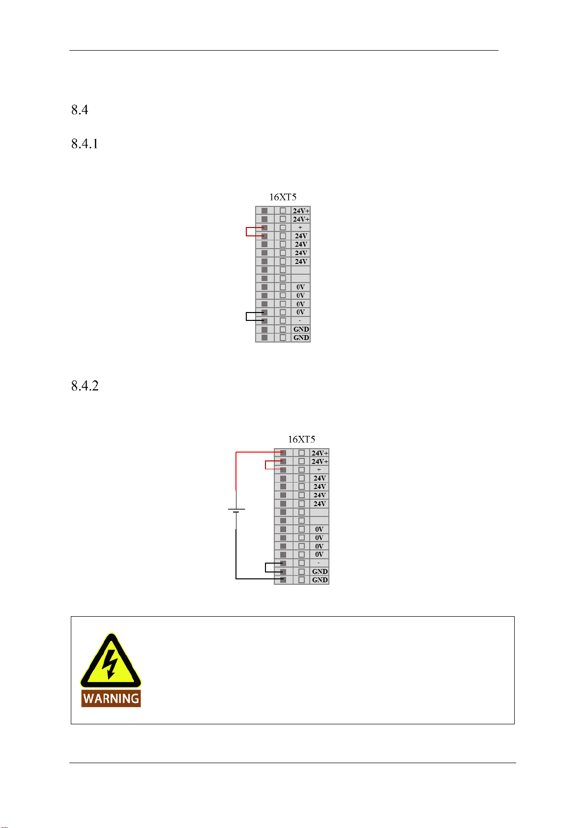
V4.5
©2015-2019 AUBO.All rights reserved. 55
panel) for device connection, software upgrade and project file export (see 10.6.6 update for usage).
Control box I/O power supply
Internal power supply
The control panel panel IO defaults to the internal power supply mode, as shown in the following figure:
Figure 8-2 Internal power supply schematic
External power supply
If the user needs to use external power supply, please use the following wiring method.
Figure 8-3 external power supply schematic
When the electrical interface of the control box is wired, the control box must be
powered off.
Page 60
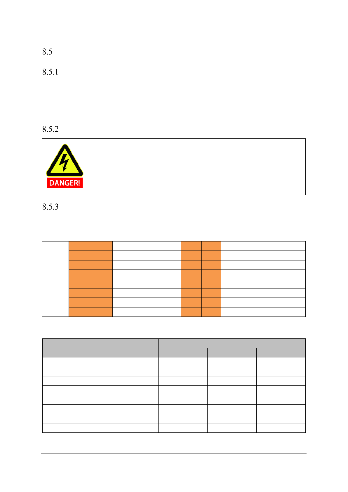
V4.5
©2015-2019 AUBO.All rights reserved. 56
Safety I/O
Introduction
The safety I/O designed as dual channel (redundant design) to ensure the safety function shall not lost in any
case of single failure. The safety devices and equipments must be implemented in accordance with the safety
instruction and finished the comprehensive risk assessment before use. The safety I/O is located on the
orange terminal block on the back panel of the control box and needs to be retained in two branches.
Safety Tips
1. Never connect safety signals to unsafety PLC which is not in correct safety level
2. Be sure to separate the safety I/O signal with normal I/O signal
3. Ensure to check the safety function before using the robot, and the safety function
must be tested regularly.
Safety I / O function definition
The safety I/O are orange color in the external panel of the control box. The safety functions are defined as
following:
Input
SI00
SI10
External Emergency Stop
SI04
SI14
Enabling Device
SI01
SI11
Safeguard Stop
SI05
SI15
Operational Mode
SI02
SI12
Reduced Mode Input
SI06
SI16
Hand Guiding Enable
SI03
SI13
Safeguard Stop Reset
SI07
SI17
System Stop Input
Output
SO00
SO10
Robot Emergenccy Stop
SO04
SO14
Not Reduced Mode
SO01
SO11
Robot Moving
SO05
SO15
System Error
SO02
SO12
Robot Not Stopping
SO06
SO16
BACKUP (Unavailable for User)
SO03
SO13
Reduced Mode
SO07
SO17
BACKUP (Unavailable for User)
Safety related electrical inputs
Safety-related electrical outputs
Safety Input Functions
Worst Case
Detection time
Power off time
Response time
External Emergency Stop
100ms
1200ms
1300ms
Safeguard Stop
100ms
——
1200ms
Reduced Mode Input
100ms
——
1200ms
Safeguard Stop Reset
100ms
——
1200ms
Enabling Device
100ms
——
1200ms
Operational Mode
100ms
——
1200ms
Teach Pendant Emergency Stop
100ms
1200ms
1300ms
System Stop Input
100ms
——
1200ms
Page 61
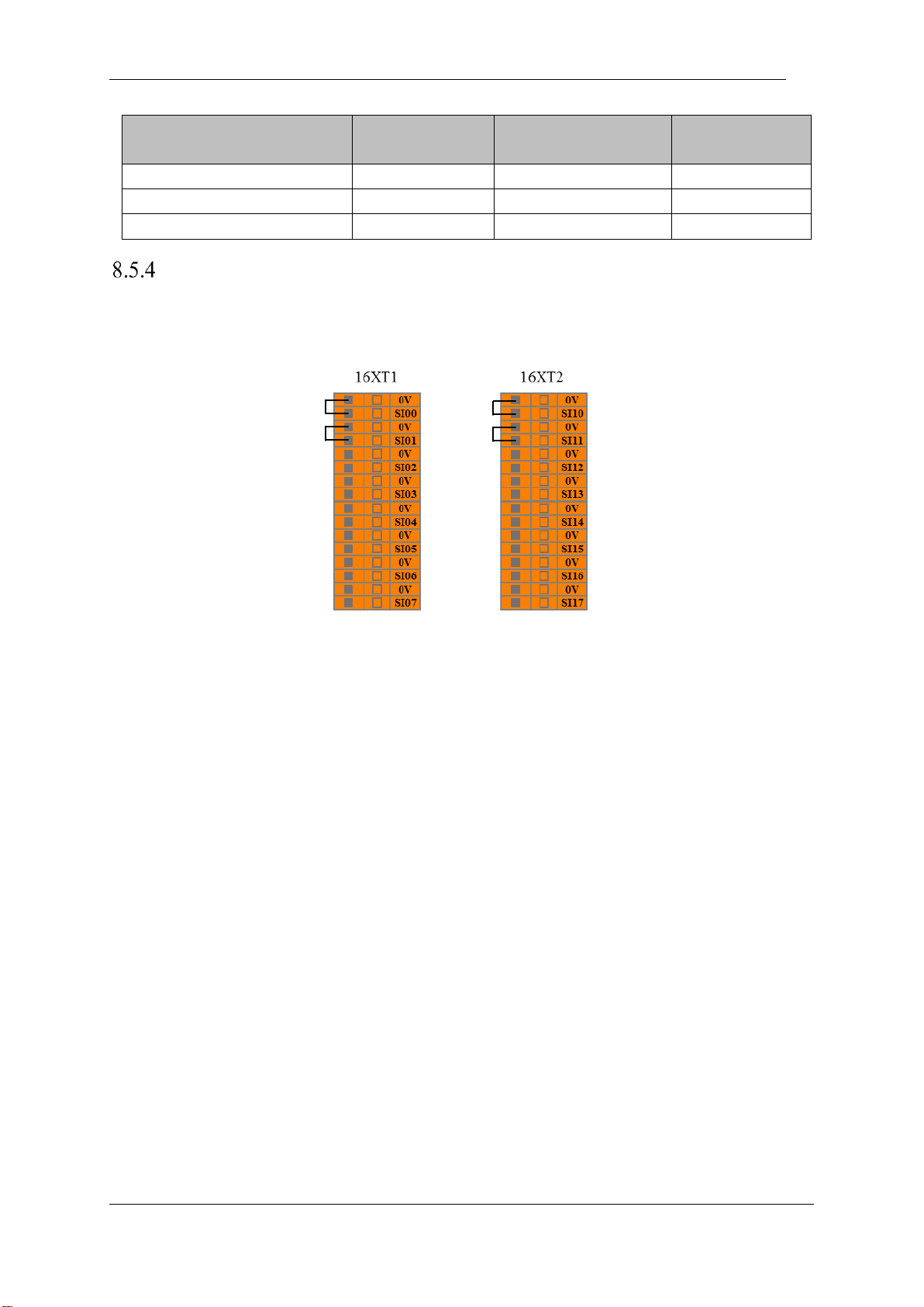
V4.5
©2015-2019 AUBO.All rights reserved. 57
Default Safety Configuration
The robot is shipped with a default configuration as below. In this case, the robot can be operated without
any additional safety equipments
Figure 8-4 Default safety configuration
Safety Output
Worst case
responding time
Safety Output
Worst case
responding time
Robot Emergenccy Stop
1000ms
REDUCED MODE
1000ms
Robot Moving
1000ms
NOT REDUCED MODE
1000ms
Robot Not Stopping
1000ms
SYSTEM ERROR
1000ms
Page 62
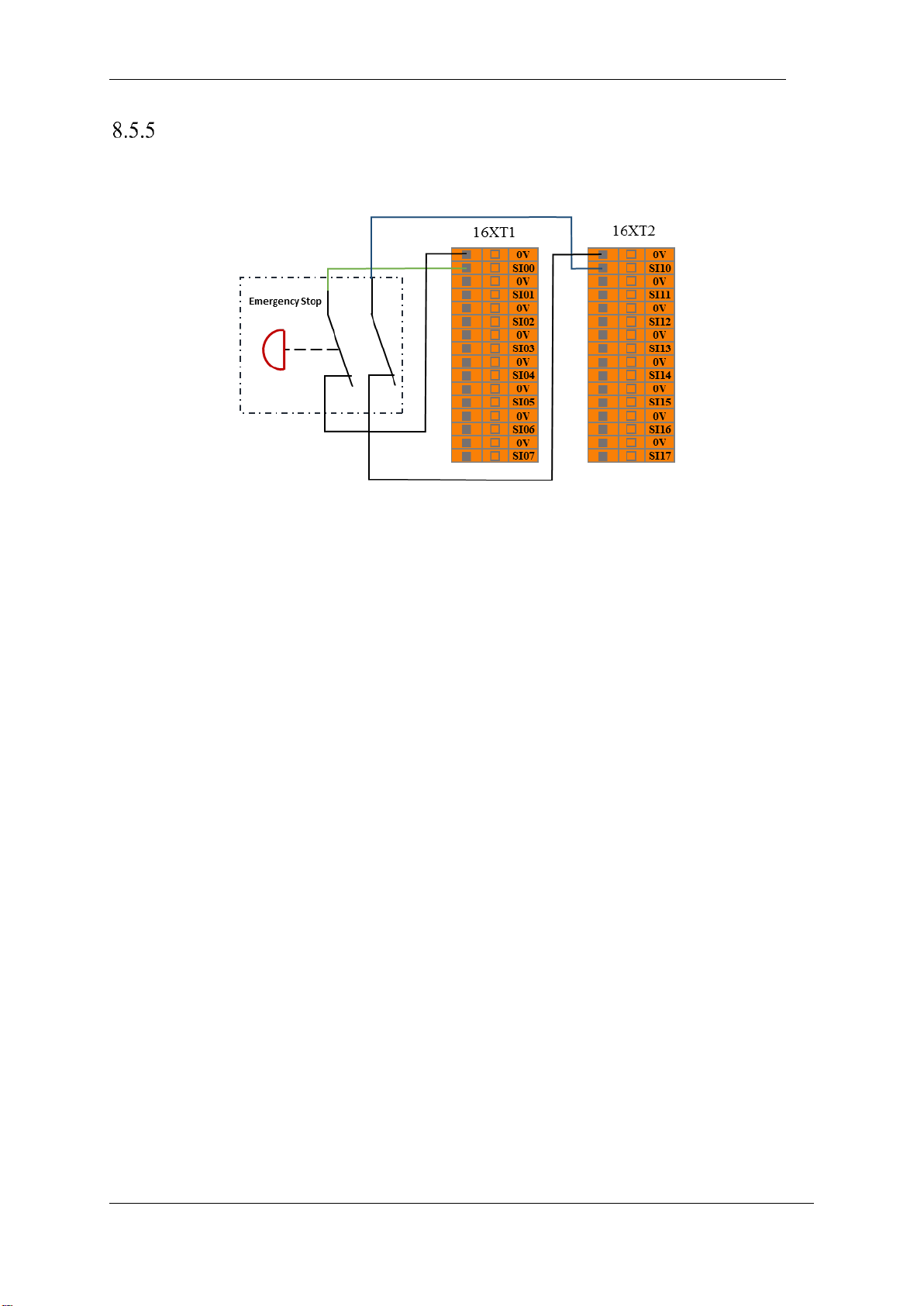
V4.5
©2015-2019 AUBO.All rights reserved. 58
External Emergency Stop Input
In the case that there is required to use one or more external emergency stop buttons, users can connect those
devices as below.
Figure 8-5 External emergency stop input
Page 63
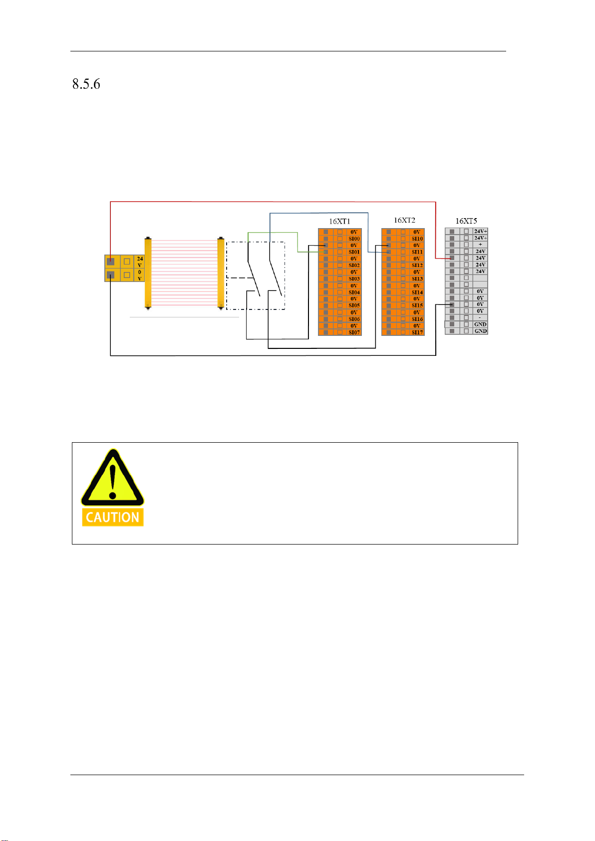
V4.5
©2015-2019 AUBO.All rights reserved. 59
Safeguard stop Input
Users can connect external safety devices (such as safety light curtains, safety laser scanners, etc.) through
this interface, then control the manipulator to enter the safeguard stop state and stop the movement of the
manipulator.
When configuring the auto-reset safeguard stop, the user can refer to the following example, using the safety
light curtain to connect to the safeguard stop input interface. See below.
Figure 8-6 Safeguard stop input (Internal Power Supply)
After the operator enters the safety zone, the robot stops moving and maintains category 2 stop. After the
operator leaves the safety zone, the robot starts automatically from the waypoint where it stopped. During
this process, there is no need to use protective reset input.
In this mode, the response time of the system is 1200ms. If the user operates too
frequently, the system may report an error.
In this configuration, user should select the protective reset as auto-reset via AUBOPE.
Page 64
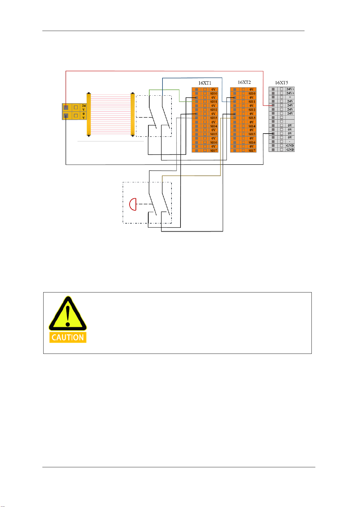
V4.5
©2015-2019 AUBO.All rights reserved. 60
When configuring the safeguard stop with reset button, the user can refer to the following example, using
the safety light curtain to connect to the safeguard stop input interface. See below.
Figure 8-7 Safeguard stop input (Internal Power Supply)
After the operator enters the safety zone, the robot stops moving and maintains category 2 stop. When the
operator leaves the safety zone, it needs to be reset from the outside of the safety zone by pressing reset
button, and then click on the AUBOPE to run. The robot continues to run from the stop point. During this
process, a protective reset input is required.
In this mode, the response time of the system is 1200ms. If the user operates too
frequently, the system may report an error.
In this configuration, user should select the protective reset as manual reset via AUBOPE.
Page 65
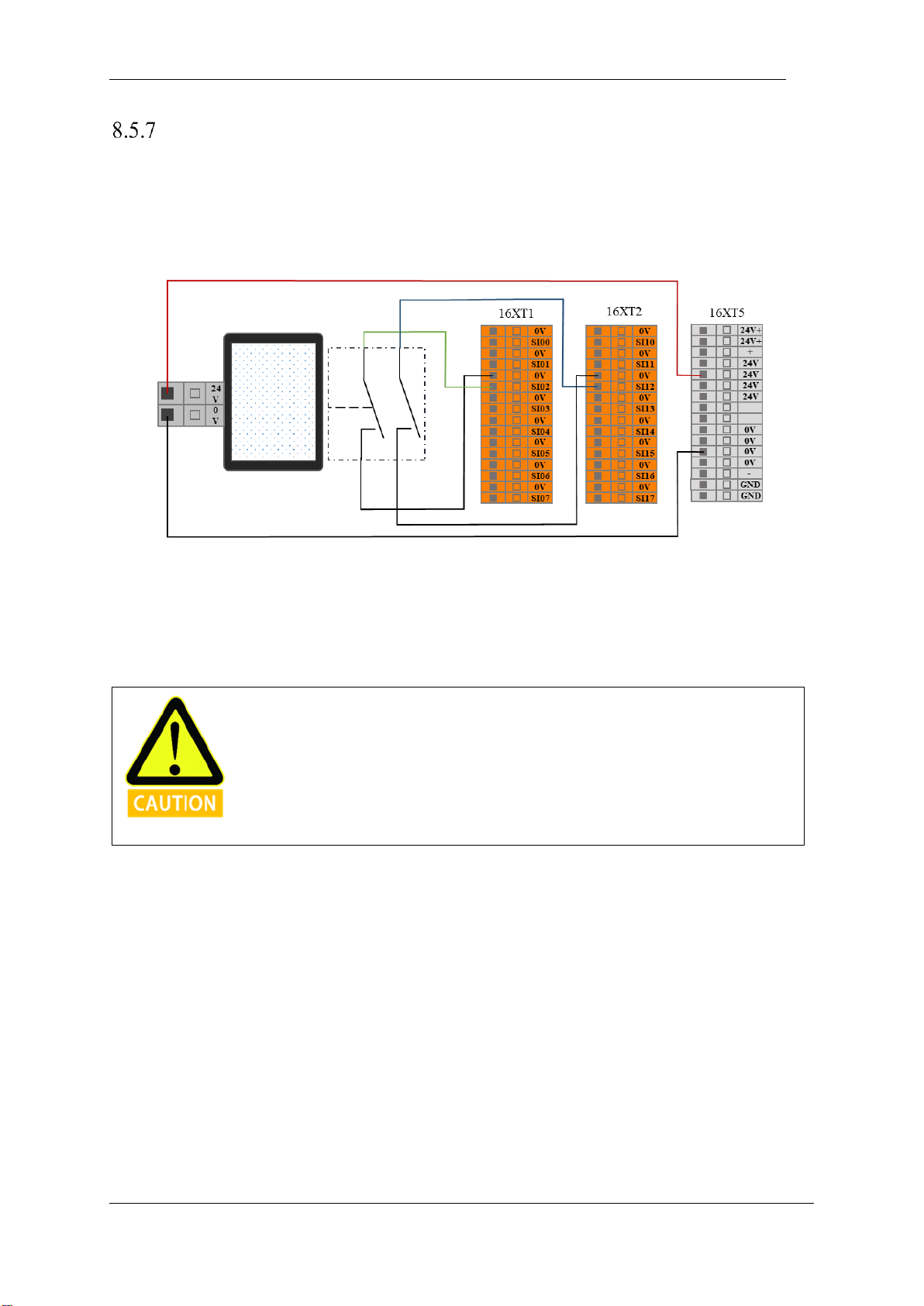
V4.5
©2015-2019 AUBO.All rights reserved. 61
Reduce Mode Input
The user can use this interface to control the manipulator enters the reduced mode. In this mode, the motion
parameters (joint speed, TCP speed) of the manipulator are limited to the user-defined reduced mode range.
The user can refer to the following example, using a safety mat to connect to the reduced mode input interface.
See the next figure.
Figure 8-8 Reduceed mode input connection
When the operator enters the safety zone, the robot enters the reduction mode, and the motion parameters
(joint speed, TCP speed) of the manipulator are limited to the user-defined reduced mode range. After the
operator leaves the safety zone, the manipulator exits the reduced mode and enters the normal mode, and the
robot moves normally.
In this mode, the response time of the system is 1200ms. If the user operates too
frequently, the system may report an error.
When using this type of configuration, the user needs to configure the reduced mode
motion parameters through the AUBOPE.
Page 66
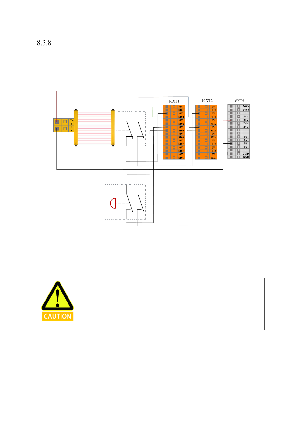
V4.5
©2015-2019 AUBO.All rights reserved. 62
Safeguard stop Resert Input
When configure the safeguard stop with reset device, users can use this interface to connect external reset
devices (reset buttons, etc.). Refer to the following example, connect the safety light curtain to the safeguard
stop input terminal and use the safety reset button to connect to the safeguard stop reset input terminal. See
the next figure.
Figure 8-9 Safeguard stop Resert Input connection (Internal power supply)
After the operator enters the safety zone, the robot stops moving and maintains at category 2 stop. When
the operator leaves the safety zone, it is necessary to reset the manipulator from the outside of the safety
zone and reset the button. The robot continues to run from the stop point. In this process, user needs to use
the safeguard stop reset input.
When using this type of configuration, the user needs to configure the protective reset as
manual reset through the AUBOPE.
Page 67
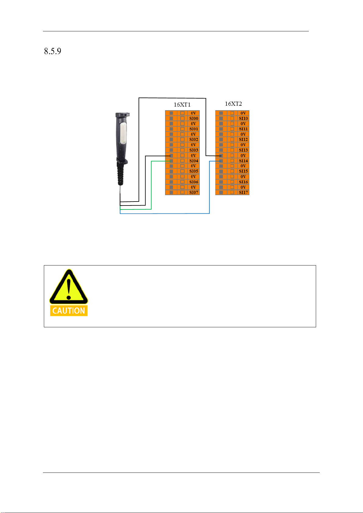
V4.5
©2015-2019 AUBO.All rights reserved. 63
Enabling Device Input
Users can use this interface to connect external safety devices (such as three-position enabling switch, etc.),
in order to verify the project. The user can refer to the following example, using the three-position enabling
switch to connect the enabling device input interface. See the next figure.
Figure 8-10 Enabling device input connection
In the verify mode, the robot starts to move when the three-position enable switch is in the enable position
(intermediate position); when the user releases or presses the three-position enable switch, the three-position
switch is in the non-enabled position, and the manipulator stops moving.
When using such a configuration, the user is required to ensure that the robot is in
verfication mode. Users can configure the operating mode through AUBOPE to
verification mode, or also through the operation mode input configure the robot to
verfication mode
Page 68
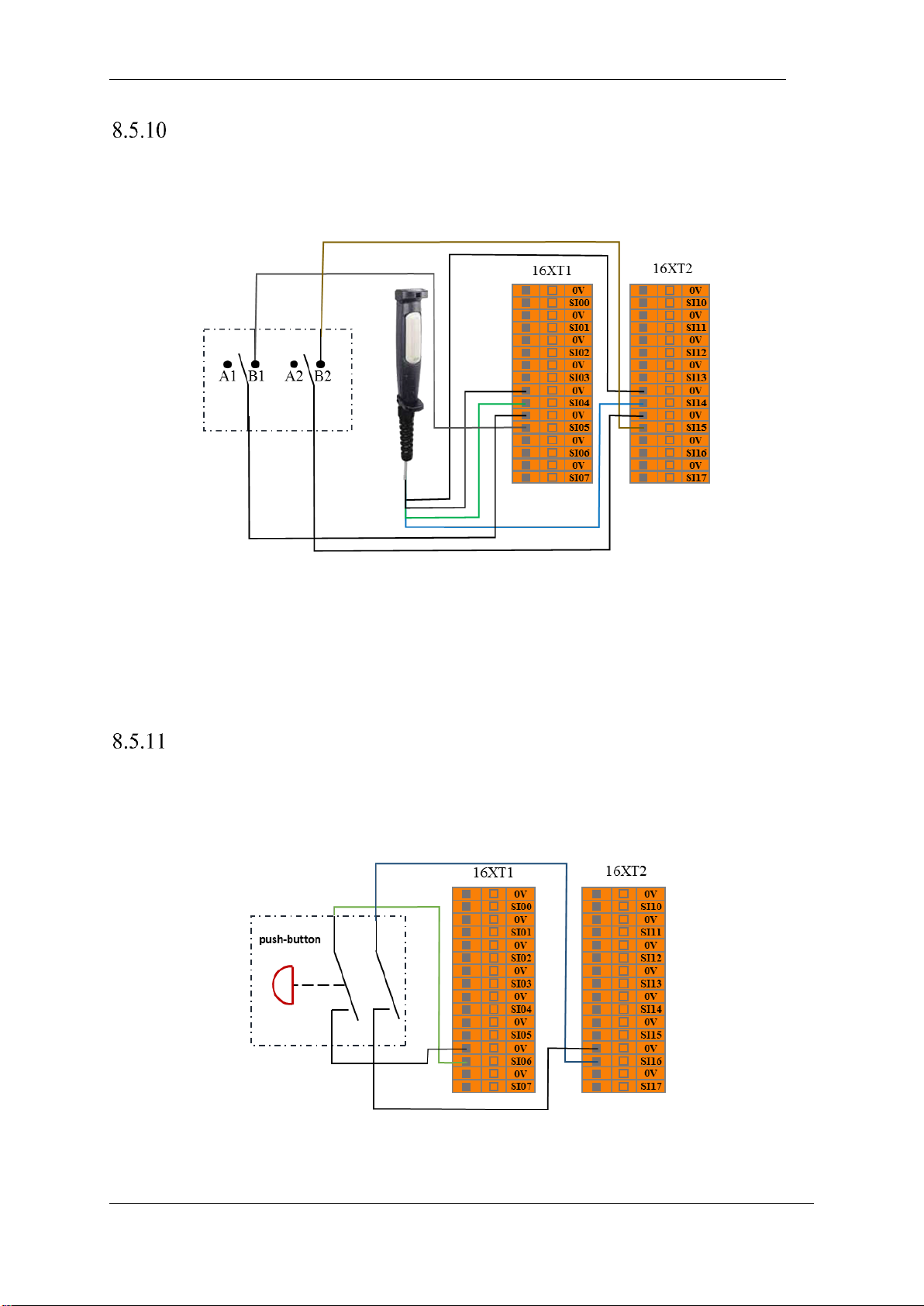
V4.5
©2015-2019 AUBO.All rights reserved. 64
Operational Mode Input
Users can use this interface to connect an external safety device (mode selector switch, etc.) and select the
robot working mode. The user can refer to the following example, using the safety selector switch to connect
to the operation mode input interface. See the next figure.
Figure 8-11 operation mode input connection
When the user switches the selector switch to the A position, the robot enters the normal mode, and the user
can use the robot normally. When the user switches the selector switch to the B position, the robot enters the
verification mode. In this mode, only when the enabling device input is valid, the manipulator executes the
verficatipon project and operates normally. When the enabling device input is invalid, the robot stops
immediately.
Hand Guiding Enable Input
User can use this interface to receive external hand guiding enable singal input, then the robot enters hand
guiding mode. The user can refer to the following example,using the hand guiding function without the force
control button in the teach pendant.
Figure 8-12 hand guiding enable input
Page 69
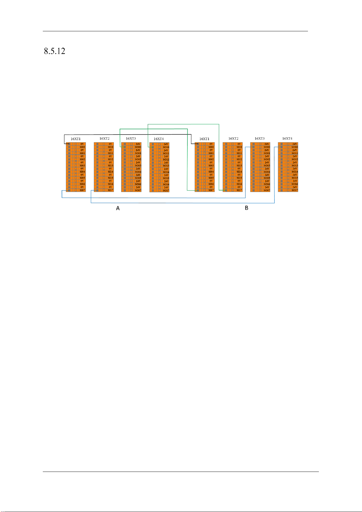
V4.5
©2015-2019 AUBO.All rights reserved. 65
System Stop Input
Users can use this interface to receive external stop signal input and control the robot to enter a category 1
stop. This input can be used in multi-machines collaboration mode, by setting a common emergency stop
line and sharing emergency stop with other machines. The operator can use the emergency stop button of
one machine to control the entire line of the machines into an emergency stop state. The user can refer to the
following example, the two robots share the emergency stop function. In this system, the emergency stop
output connected to the system stop input terminal. See the next figure.
Figure 8-13 system stop input connection
When one of them enters the emergency stop state, the other will immediately enter the emergency stop state
to achieve the function of two machines share emergency stop
Page 70
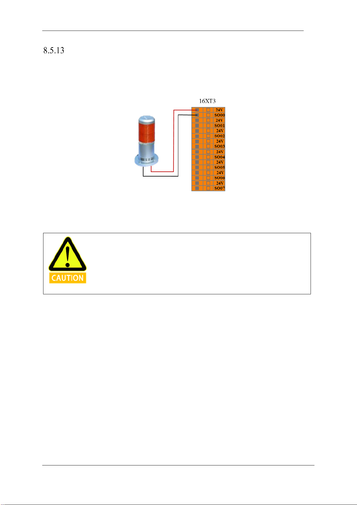
V4.5
©2015-2019 AUBO.All rights reserved. 66
Robot Emergency Stop Output
The user can use this interface when the robot enters the emergency stop state. It will output an emergency
stop signal. The user can refer to the following example to connect the external alarm light to the system
emergency stop output interface. See the next figure.
Figure 8-14 robot emergency stop output connection
In this configuration, when the robot enters the emergency stop state, it outputs a system emergency stop
signal and the external alarm light.
This function is widely used and, in any case, requires a complete risk assessment by
users or Integrators.
Page 71
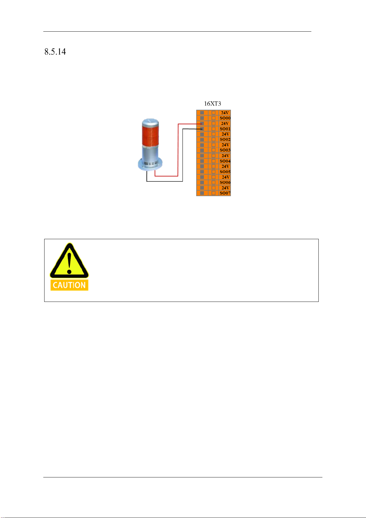
V4.5
©2015-2019 AUBO.All rights reserved. 67
Robot Moving Output
Through this interface, the user can outputs the robot moving signal to the outside when the robot moves
normally. The user can refer to the following example to connect the external indicator to the robot moving
output interface. See the figure below.
Figure 8-15 Figure robot moving output connection
In this configuration, when the robot moves normally, device outputs the robot moving signal to the outside
and the external robot moving status indicator lights.
This function is widely used and, in any case, requires a complete risk assessment by
users or Integrators.
Page 72
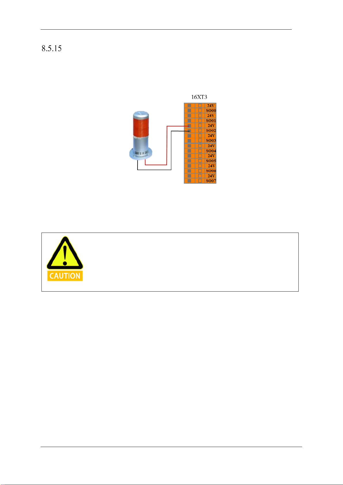
V4.5
©2015-2019 AUBO.All rights reserved. 68
Robot Not Stopping Output
T through this interface, when the robot receives the stop signal and decelerates the moving, the robot has
not yet completely stopped. It outputs a robot not stopping signal. The user can refer to the following example
to connect the external indicator to the robot not stopping output interface. See the figure below.
Figure 8-16 robot not stopping output connection
In this configuration, when the robot receives the stop signal and decelerates the moving, robot has not yet
completely stopped, it outputs a robot not stopping signal and the external robot not stopping status indicator
lights.
This function is widely used and, in any case, requires a complete risk assessment by
users or Integrators.
Page 73
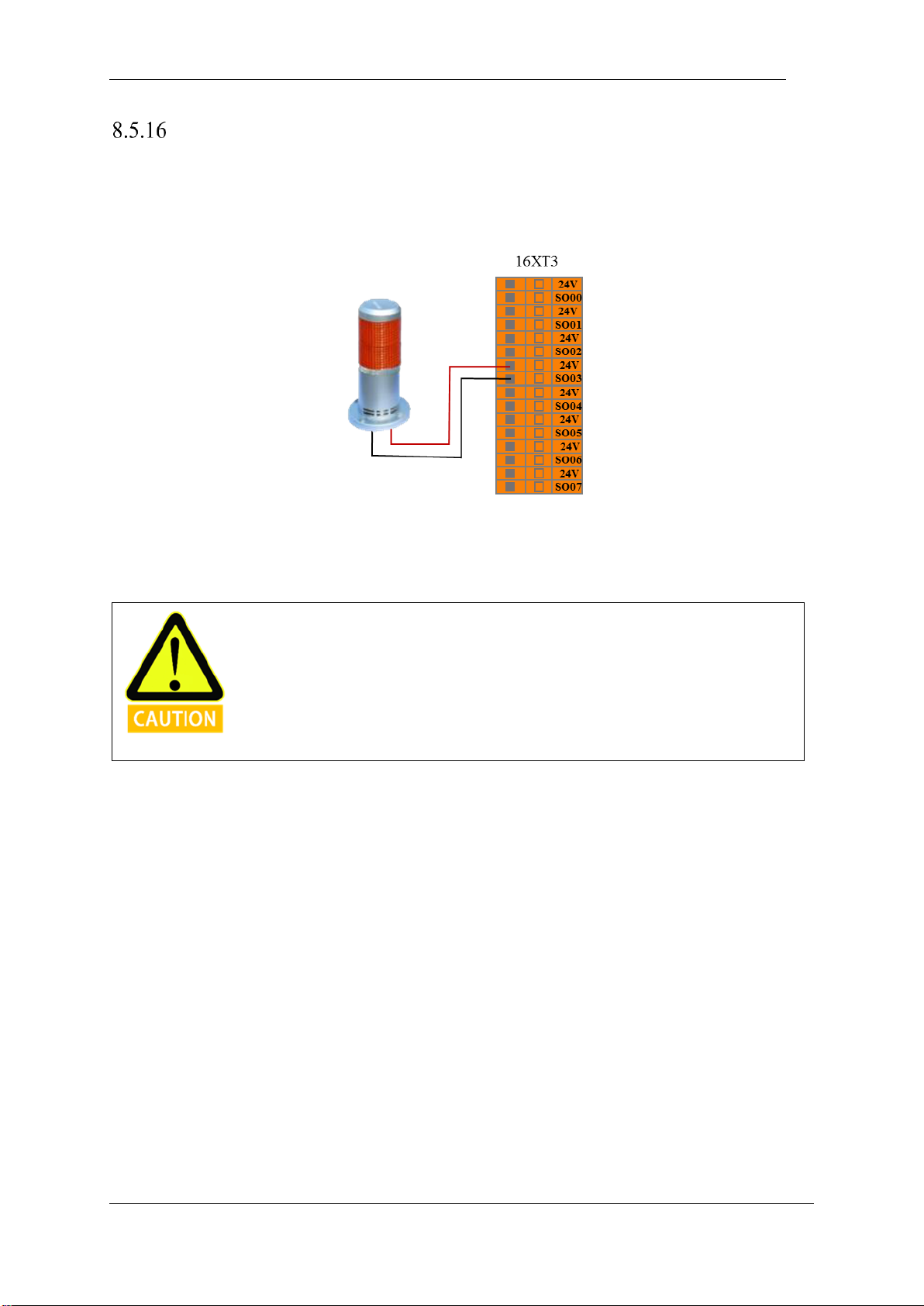
V4.5
©2015-2019 AUBO.All rights reserved. 69
Reduced Mode Output
The user can use this interface to output a reduced mode signal to the external environment when the robot
enters the reduced mode. The user can refer to the following example to connect the external indicator to the
reduced mode output interface. See the figure below.
Figure 8-17 reduced mode output connection
In this configuration, when the robot enters the reduced mode, it outputs a reduced mode signal and the
external reduction mode indicator lights
This function is widely used and, in any case, requires a complete risk assessment by
users or Integrators.
Page 74
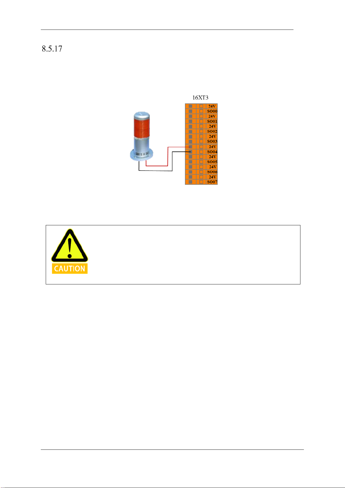
V4.5
©2015-2019 AUBO.All rights reserved. 70
Not Reduced Mode Output
The user can use this interface to output a not reduced mode signal to the external when the robot enters the
not reduced mode. The user can refer to the following example to connect the external indicator to the not
reduced mode output interface. See the figure below.
Figure 8-18 not reduced mode output connection
In this configuration, when the robot enters the not reduced mode, it outputs a not reduced mode signal and
the external not reduction mode indicator lights
This function is widely used and, in any case, requires a complete risk assessment by
users or Integrators.
Page 75
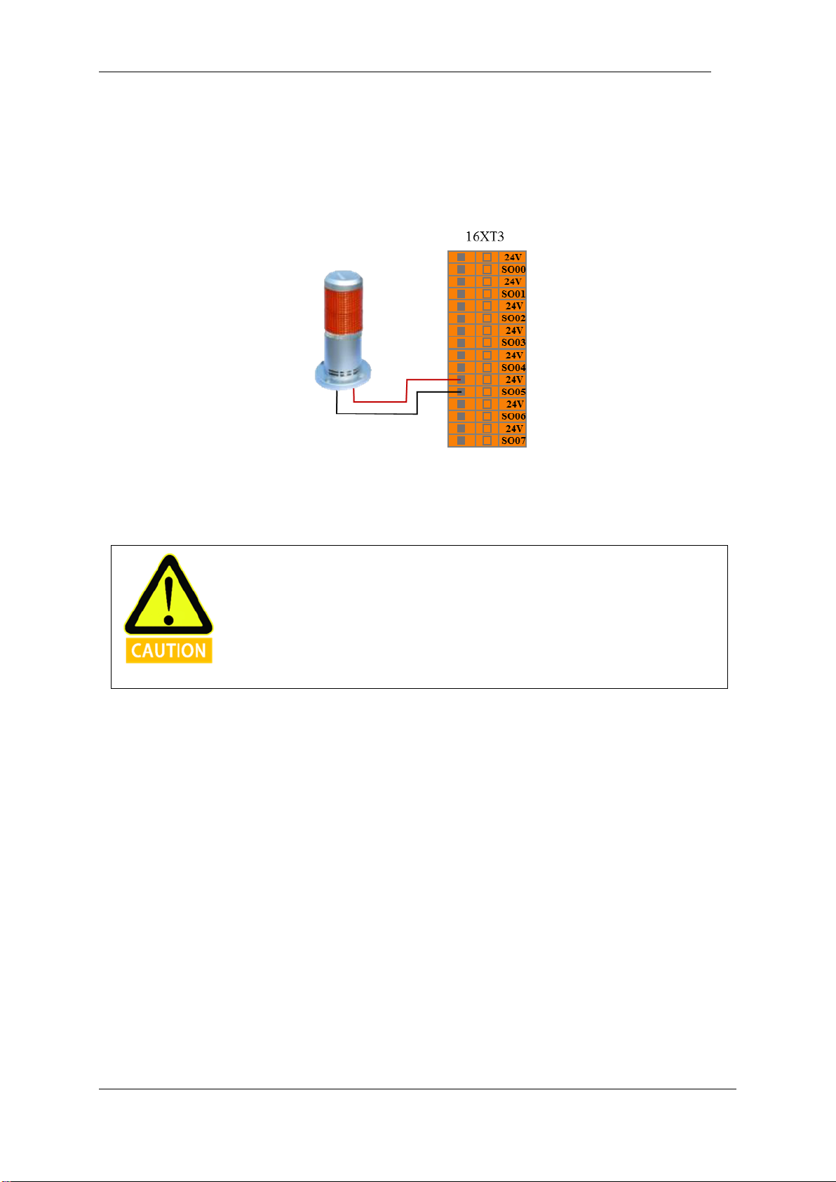
V4.5
©2015-2019 AUBO.All rights reserved. 71
8.5.18 System Error Output
The user can use this interface, and when the robot system has an error, it outputs a system error signal to
the outside. The user can refer to the following example to connect the external indicator to the system error
output interface. See the figure below.
Figure 8-19 System error output connection
In this configuration, when the robot system error alarms, it outputs a system error signal and the external
system error indicator light.
This function is widely used and, in any case, requires a complete risk assessment by
users or Integrators.
Page 76
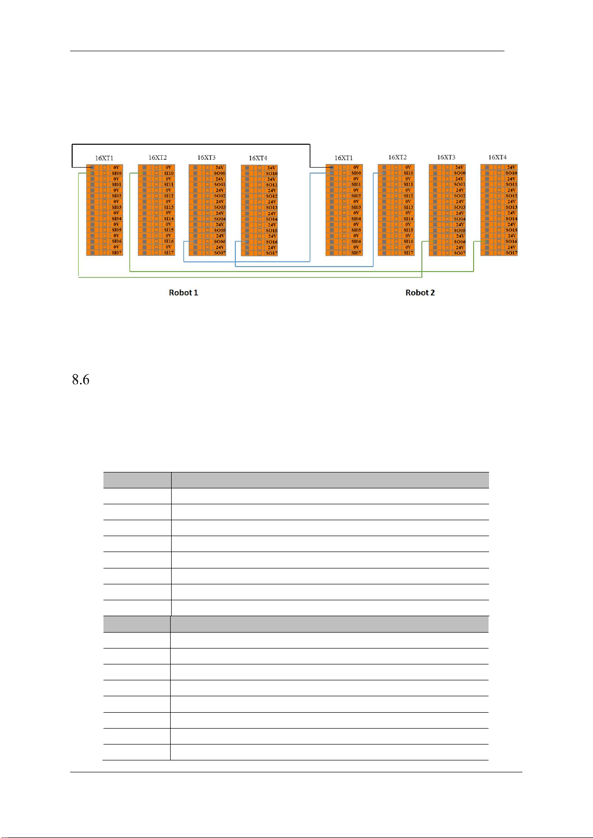
V4.5
©2015-2019 AUBO.All rights reserved. 72
8.5.19 Non-stop continuous Output
This interface outputs a continuous signal until an emergency stop occurs. The user can use this interface to
stop the two robot arms from each other.
Internal I/O
The internal IO of the control box is an internal function interface, which provides the I/O status display of
the internal interface board of the controller. This part of the interface is not open to the user. The user can
view the internal I/O status through the teach pendant interface (see10.3.1Controller I/O Tab). The internal
IO status of the control box is described in the following table:
Input
Function
CI00
Linkage/Manual
CI01
Host/Slave
CI02
Power Contactor for Manipulator
CI03
Control Box Emergency Stop
CI10
Manipulator On
CI11
Manipulator Off
CI12
Power Contactor for Manipulator
CI13
Control Box Emergency Stop
Output
Function
CO00
Stand By
CO01
Emergency Stop
CO02
Linkage/Manual
CO03
AUBOPE Running
CO10
Back Up
CO11
Emergency Stop
CO12
Back Up
CO13
Back Up
Page 77
V4.5
©2015-2019 AUBO.All rights reserved. 73
General I/O
The AUBO interface board has 16 digital input interfaces, 16 digital output interfaces, 4 pairs of analog
differential input interfaces, 2 pairs of analog voltage output interfaces and 2 pairs of analog current output
interfaces which electrical errors are about ±1%.
The following table lists the function’s definitions of the various I/O. Users must follow the requirements in
the table. In addition, users should note that buttons and switches on control panel occupy part of the I/O.
IO Specification
All AUBO robot IOs are set to NPN mode, which means low voltage level effective. When an User IO is set
to “Effective” or “High” on the teach pendant, the actual voltage level at the IO output is low.
Note Open circuit protection is set in each IO. Therefore, whenever an IO is not connected in a closed circuit,
its output voltage is going to remain at high even if the IO is set to “Effective” by script or by teach pendant.
For digital IO outputs, the method to check the IO status is to measure the resistance between DO and 0V.
When the DO is set to “Effective” or “High”, the resistance goes to approximately 0Ω, otherwise the
resistance is about 12KΩ.
When connecting external devices, all external devices should be connected to the
ground with the control box.
General purpose digital I/O interface
The general purpose digital I/O interface is located on the back panel interface board of the control box.
16 users on the control box can use the general purpose digital input terminal (the "DI terminal" to
represent the digital input terminal), they all work in the NPN mode, that is, the DI terminal and the ground
conduction can trigger the action, and the DI terminal is disconnected from the ground. Does not trigger an
action.
The DI terminal can read the action signals of the switch button, sensor, PLC or other AUBO robot.
The 16 users on the control box can use the general digital output (hereinafter referred to as the "DO end"
to indicate the digital output), which all work in the form of NPN. The working process of the DO terminal
can be expressed as shown in the following figure. When a logic "1" is given, the DO terminal and GND
are turned on; when a logic "0" is given, the DO terminal is disconnected from the GND.
Page 78
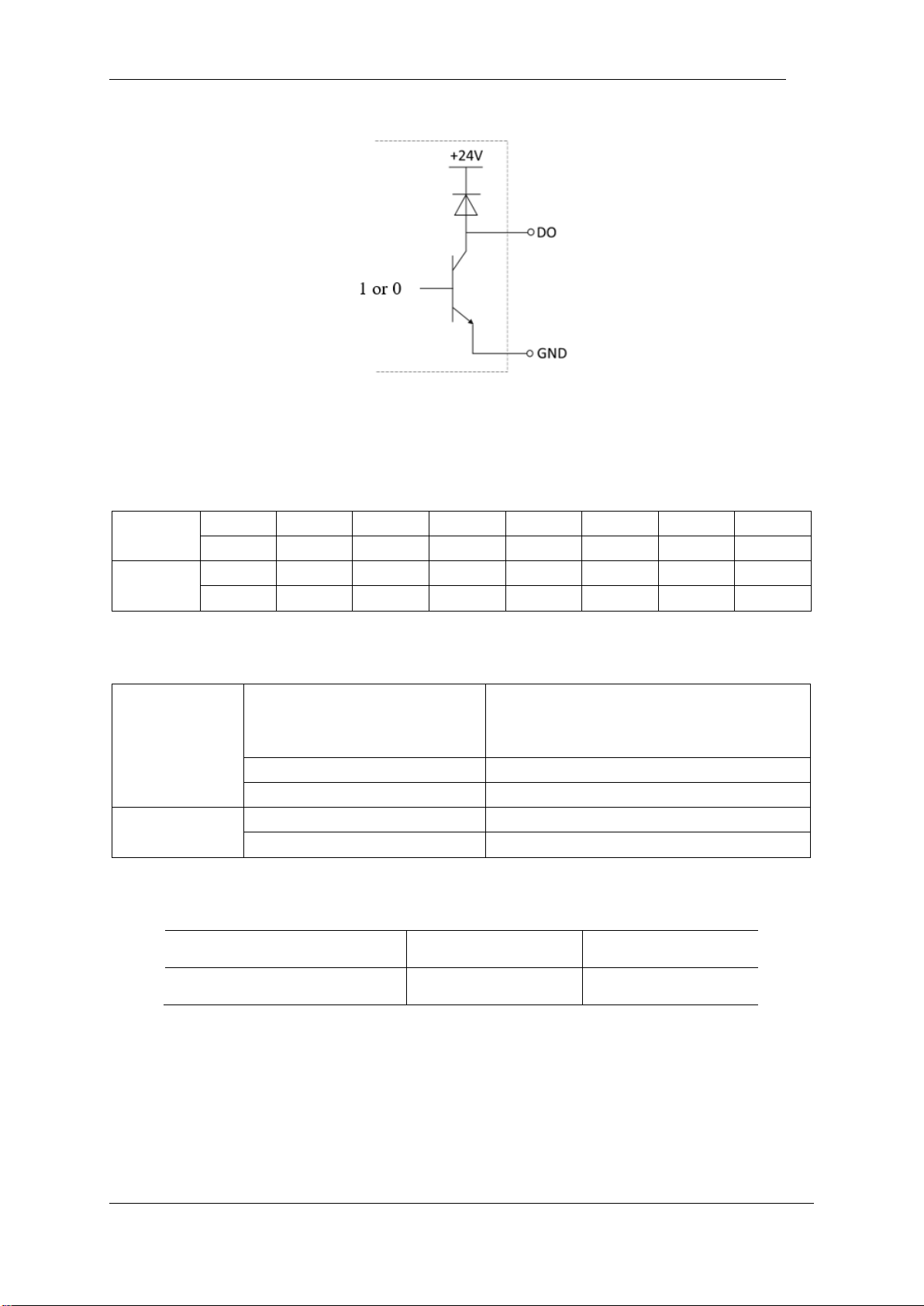
V4.5
©2015-2019 AUBO.All rights reserved. 74
Figure 8-20 DO connect GND
The DO end can be directly connected to the load or communicate with a PLC or other robot.
The user can control the above digital IO through the teach pendant AUBORPE software.
Input
DI00
DI01
DI02
DI03
DI04
DI05
DI06
DI07
DI10
DI11
DI12
DI13
DI14
DI15
DI16
DI17
Output
DO00
DO01
DO02
DO03
DO04
DO05
DO06
DO07
DO10
DO11
DO12
DO13
DO14
DO15
DO16
DO17
Electrical parameter specification
DI
Input form
P-lesend
No-voltage contact input
NPN open collector transistor
Input method
Input signal current
Electrical specifications
5mA/DC24V
DO
Output form
Transistor (P-lesend type)
Electrical specifications
300mA/DC24V
Electrical parameters
Parameter term
minimum value
Maximum value
Single DI input voltage
0 V
24 V
Example
Some common wiring examples are listed below.
DI end connection button switch
As shown in the figure below, the DI terminal can be connected to ground (G) through a normally open
Page 79
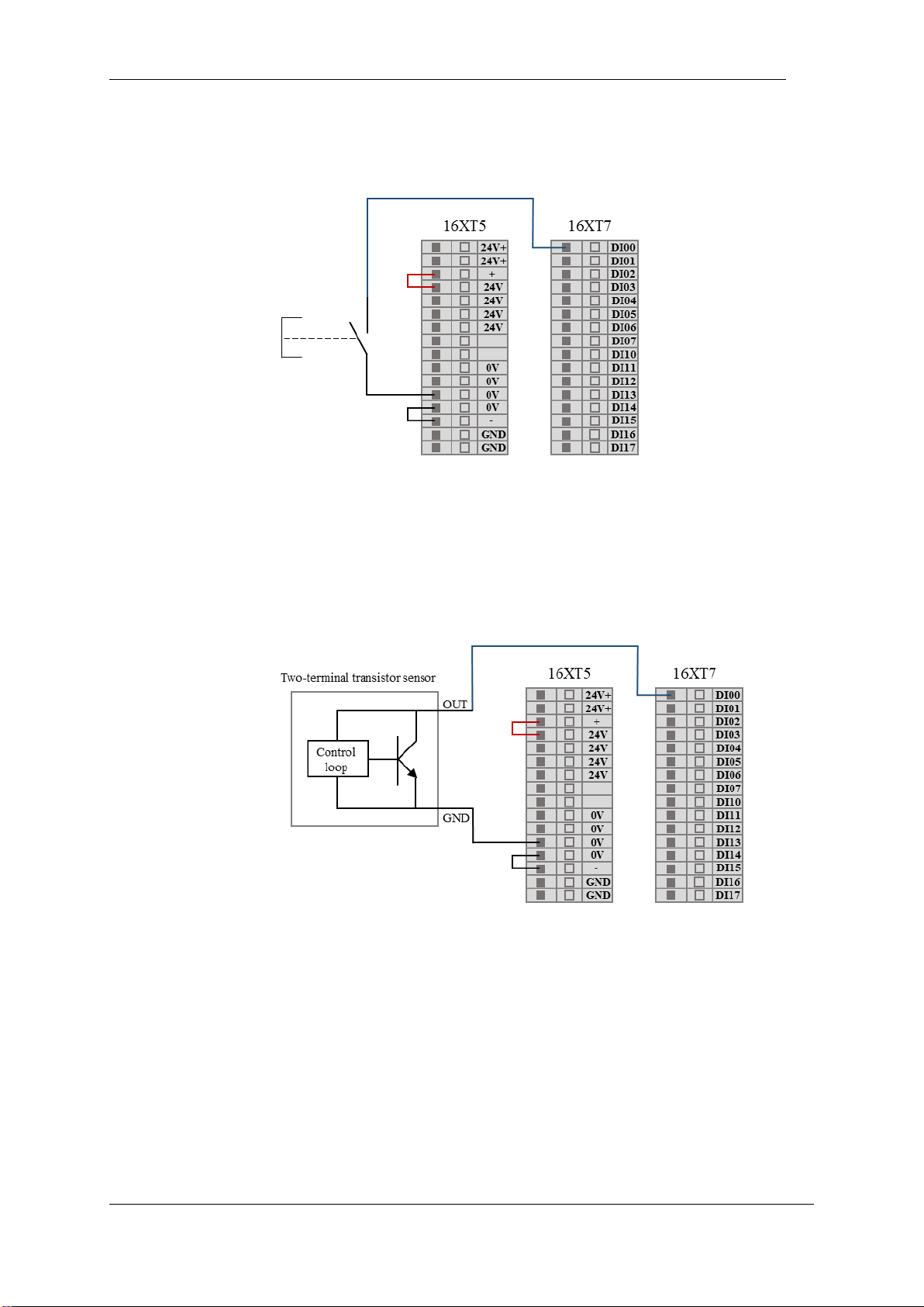
V4.5
©2015-2019 AUBO.All rights reserved. 75
button. When the button is pressed, the DI terminal and GND are turned on to trigger the action. When the
button is not pressed, the DI terminal is disconnected from GND, and no action is triggered. This is the
simplest wiring example.
Figure 8-21 DI end connection button switch schematic
DI end connection two-end sensor
As shown in the figure below, there is a sensor connected between the DI terminal and GND. If the voltage
difference between the OUT terminal and the GND terminal is small when the sensor is working, the
action can be triggered. When the sensor is not working, the loop is disconnected and the action is not
triggered.
Figure 8-22 DI connect to two-terminal sensor
DO termination load
Page 80
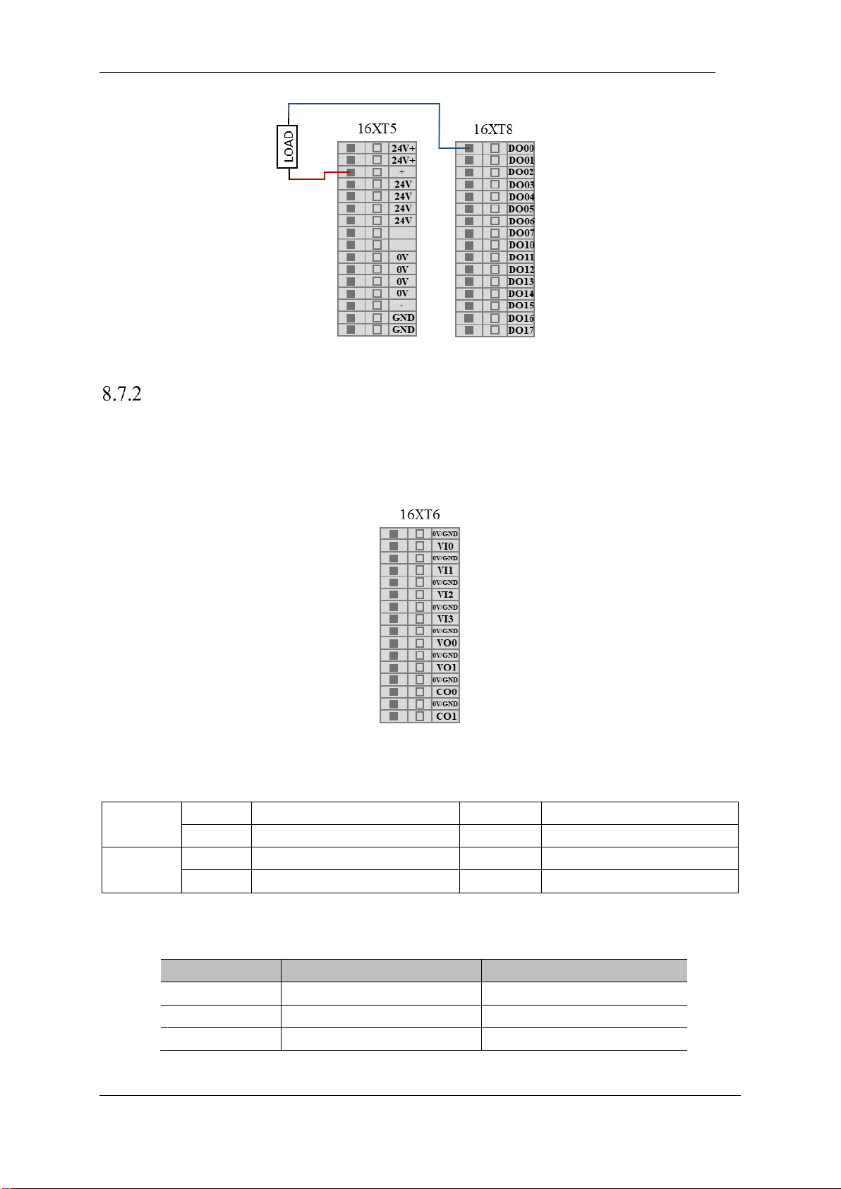
V4.5
©2015-2019 AUBO.All rights reserved. 76
Figure 8-23 DO connect to load
Analog I/O interface
The analog I/O interface is located on the interface board on the back of the control box. There are 4 pairs
of analog voltage input interfaces, indicated by VI. There are 2 analog voltage outputs and 2 analog current
outputs, which are represented by VO and CO respectively. As shown below.
Figure 8-24 Analog I/O interface diagram
General purpose analog input and output available to users
Input
VI0
Analog voltage input
VI2
Analog voltage input
VI1
Analog voltage input
VI3
Analog voltage input
Output
VO0
Analog voltage output
CO0
Analog current output
VO1
Analog voltage output
CO1
Analog current output
General purpose analog input and output interface electrical parameter specifications available to
users
Type
voltage
current
Input
0~+10V
-
Output
0~+10V
0~20mA
Accuracy
±1%
±1%
Page 81
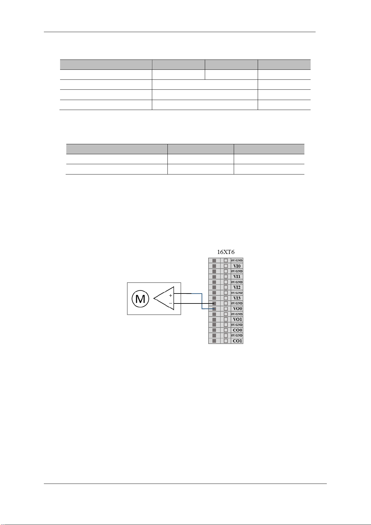
V4.5
©2015-2019 AUBO.All rights reserved. 77
Electrical parameters at the VI end
Parameter term
Minimum value
Maximum value
Units
Input voltage
0
+10 V Input resistance
100K
Ω
VI sampling resolution
12
BITS
VI sampling accuracy
10
BITS
VO end electrical parameters
Parameter term
minimum value
Maximum value
Single VO terminal input voltage
0V
+10 V
Single CO terminal input current
0mA
20 mA
Example
Analog voltage output wiring method
For the analog voltage output, refer to the wiring method shown in the figure below.
Figure 8-25 Analog output drive differential device
Analog voltage input wiring method
External sensor wiring:
Page 82
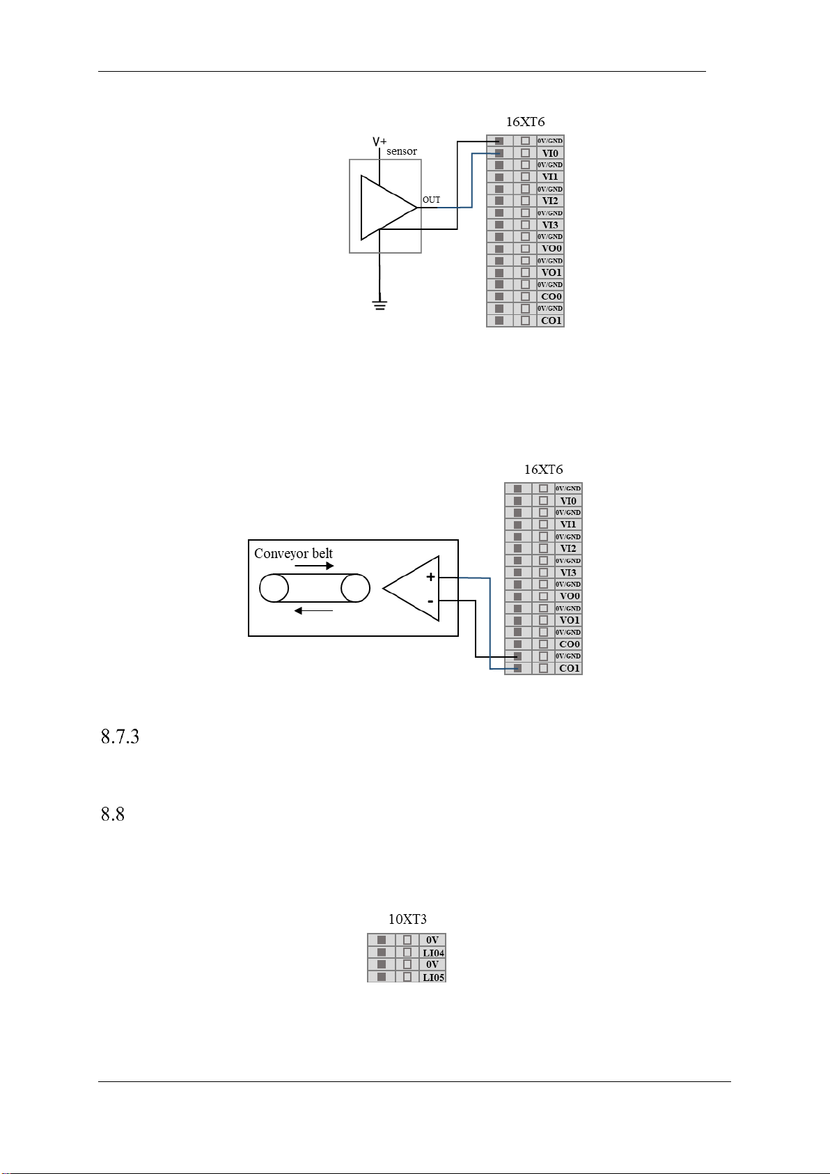
V4.5
©2015-2019 AUBO.All rights reserved. 78
Figure 8-26 connect to sensor
Analog current output wiring method5
The analog current output can be wired as shown in the figure below.
Figure 8-27Analog current output connect to current source
Clear alarm signal interface
F6 on the back panel of the control box is the clear alarm signal interface. This signal is active low.
Remote switch control I/O interface
The remote power on/off control I/O interface is located on the back panel interface board of the control
box, as shown in the figure below.
Figure 8-28 Remote I/O interface control I/O interface
Using the remote power on/off control I/O interface allows you to control the teach pendant and robot
body to be turned on or off without the use of a teach pendant.
Page 83
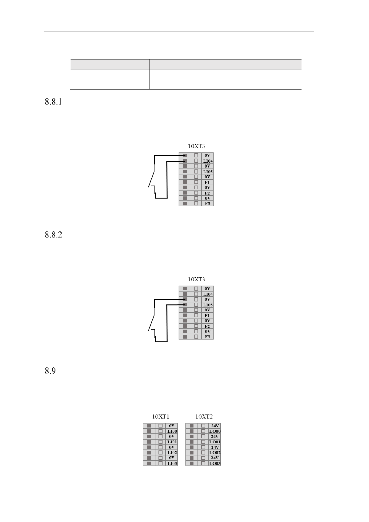
V4.5
©2015-2019 AUBO.All rights reserved. 79
Table 1 Remote Switch Control I/O Interface
Input
Functional description
LI04
Remote boot signal input interface
LI05
Remote shutdown signal input interface
Remote power on
This example shows how to connect the remote boot interface, ie the teach pendant and the robot are
powered up after the switch is closed.
Figure 8-28 schematic diagram of remote boot wiring
Remote power off
This example shows how to connect the remote shutdown interface, ie the teach pendant and the robot are
powered off after the switch is closed.
Figure 8-29 Remote shutdown wiring diagram
Linkage Control I/O Interface
The linkage control I/O interface is located on the interface board on the back of the control box and is
represented by LI/LO, as shown in the figure below.
Figure 8-30 Schematic diagram of linkage control I/O interface
Page 84

V4.5
©2015-2019 AUBO.All rights reserved. 80
The linkage control interface can be used to control the movement state of the robot body from the teach
pendant. For details on the usage, see7.4.2Linkage mode.
Page 85
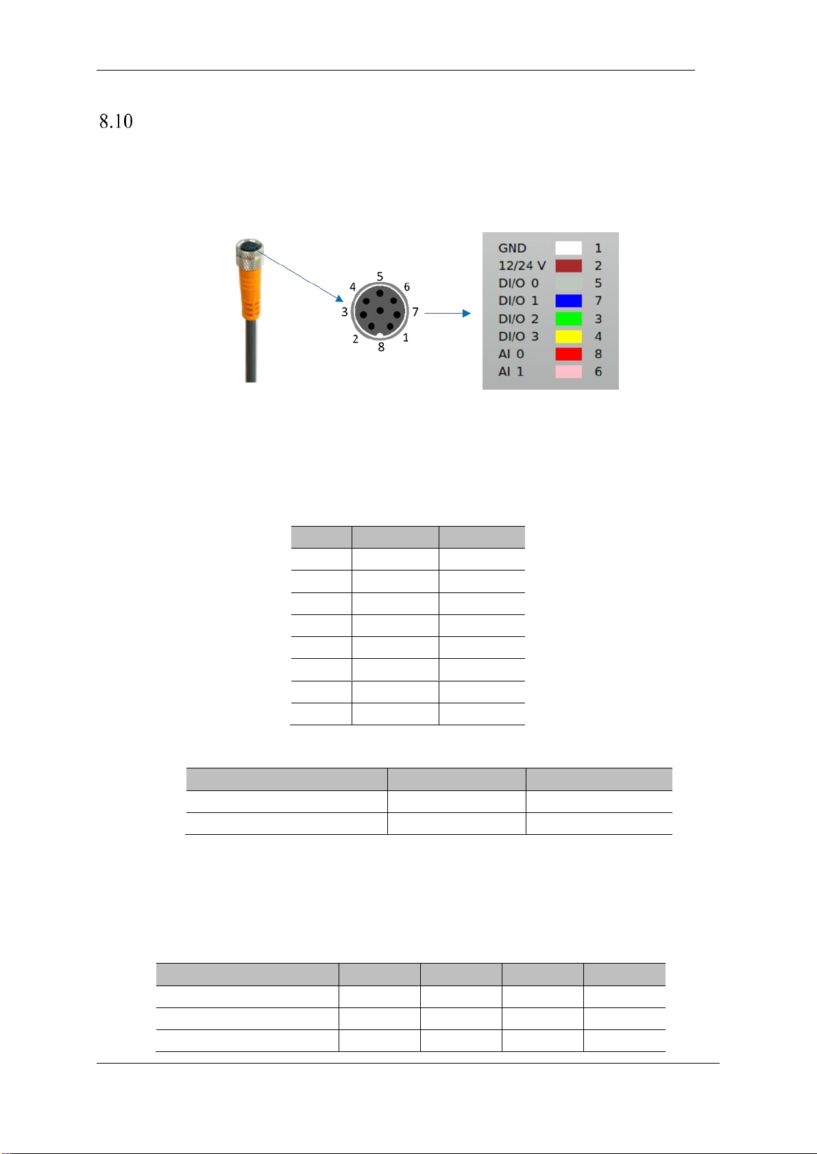
V4.5
©2015-2019 AUBO.All rights reserved. 81
Robot Tool I/O Interface
There is a 8-pins mini connector on end-effector, which electrical error is about±10%, to provide power
and control signals to specific tools (Holder for example) used in the end. Wiring as shown below.
Figure 8-29 connecting cables
Analog terminal electrical parameters
The eight wires inside the Lumberg RKMV 8-354 industrial cable have different colors. The different colors
designate different functions, see table below:
Pin
Color
Signal
1
White
GND
2
Brown
12/24V
5
Gray
DI/O 0
7
Blue
DI/O 1
3
Green
DI/O 2
4
Yellow
DI/O 3
8
Red
AI 0
6
Pink
AI 1
Table 22 Electrical parameters of the analog end
Parameter item
Min
Max
Voltage input analog AI 0
0V
+10 V
Voltage input analog AI 1
0V
+10 V
Power supply electrical parameters
In the IO tab of the graphical user interface, set the internal power supply to 0V, 12V, 24V. The electrical
specifications are as follows.
Table 23 Electrical parameters in different modes of power supply
Parameter
Min
Typ
Max
Unit
Supply voltage in 24V mode
23
24
25
V
Supply voltage in 12V mode
11.5
12
12.5
V
Supply current in two modes
-
0.8
1.0
A
Page 86
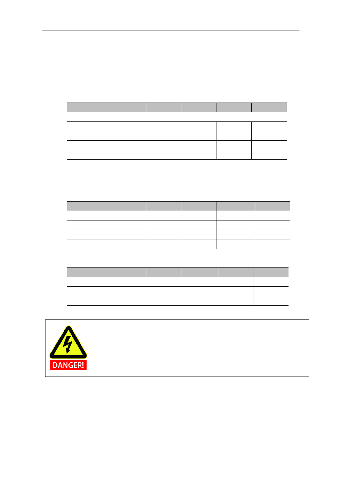
V4.5
©2015-2019 AUBO.All rights reserved. 82
Tool digital output
The digital output is implemented in the form of NPN. After the digital output is activated, the corresponding
connector will be driven to GND. After the digital output is disabled, the corresponding connector will be open.
The electrical specifications are as follows:
Table 24 Tool Digital Output Electrical Parameters
Parameter
Min
Typ
Max
Unit
Voltage at open circuit
Same supply voltage
Voltage when inputting 1A
current
0.35
0.4
0.85
A
Input Current
0.35
0.4
0.5 A Current through GND
0.35
0.4
0.5
A
Tool digital input
The digital input is implemented as an NPN with a weak pull-down resistor as shown in the following
figure:
Parameter
Min
Typ
Max
Unit
Input voltage
-0.5
-
Vout+2
V
Logic low voltage
0
1.5 2 V
Logic high voltage
Vout-4
Vout
Vout+2 V Input resistance
-
4.3 - k.
Tool IO
Parameter
Min
Typ
Max
Unit
Input voltage in voltage mode
0 - 10
V
Input resistance resolution in
the 0V to 10V voltage range
-
0.0024
-
mV
When connecting thetool and the holder, ensure that there is no danger when interrupting
the power supply, such as dropping the workpiece from the tool.
Page 87

V4.5
©2015-2019 AUBO.All rights reserved. 83
Page 88
V4.5
©2015-2019 AUBO.All rights reserved. 84
9. GETTING STARTED
Basic function introduction
The robot body is an execution part of the robot system, wherein the base is for mounting the robot body,
the shoulder and the elbow perform a large amplitude action, the wrist 1 and the wrist 2 perform a finer
motion, and the wrist 3 can be connected with the end tool.
The control box is the control part of the robot system, which can control the movement position, posture
and trajectory of the robot in the work space, and the electrical input and output terminals of the connected
equipment.
The teach pendant is the display and operation part of the robot system. It has a human-computer
interaction interface for menu operation, programming and online operation. The user can directly operate
and control the robot body to perform related tasks through the AUBORPE software displayed on the teach
pendant interface. .
Take out the AUBO robot from the packing box and install it on the base. Please read the
specific installation instructions in chapter 6: Installation.
1. Control box should be placed horizontally on the ground. A gap of 50mm on each
side is needed for sufficient air circulation
2. The teach pendant can be hung on the control box. Make sure that no one can step on
the cable.
1. Make sure that the control box, teach pendant, and cables are not incontact with
liquids. A wet control box cancause casualtie.
2. The control box and the teach pendant should not be exposed to dusty or wet
environments that exceed IP20 rating. Pay close attention to the environment that
contains conductive dust.
Page 89

V4.5
©2015-2019 AUBO.All rights reserved. 85
Installing the robot system
Install the robot body and control box (see Chapter6 ROBOT INSTALLATION, for specific installation
instructions and warning information) before using AUBORPE. Refer to the following procedure to install
the robot system.
1. Unpacking the robot body, control box, teach pendant, and related cables;
2. Mount the robot body to a strong, shock-resistant surface;
3. Put the control box in the proper position;
4. Hang the teach pendant at the hook on the side of the control box;
5. Connect the cable to the corresponding robot body, control box and teach pendant. (Please refer to 6.6
Cable connection for specific connection instructions and warning information.
6. It is determined that the safety information in Chapter 6 ROBOT INSTALLATION has been observed
and the warning information has been circumvented;
7. Plug in the power plug of the control box;
Power on the manipulator
Preparation
➢ Check the connection of the manipulator and the control box.
➢ Check the connection of the teach pendant and the control box.
➢ Check the connection of the power cable and the control box.
➢ Check whether the power switch of the control box is shutdown when robot is unpowered.
➢ Check whether the emergency stop button on the control box and the teach pendant is pop-up.
➢ Check whether the mode switch key is in right position.
➢ Ensure the robot never hit any personnel or equipment.
Page 90
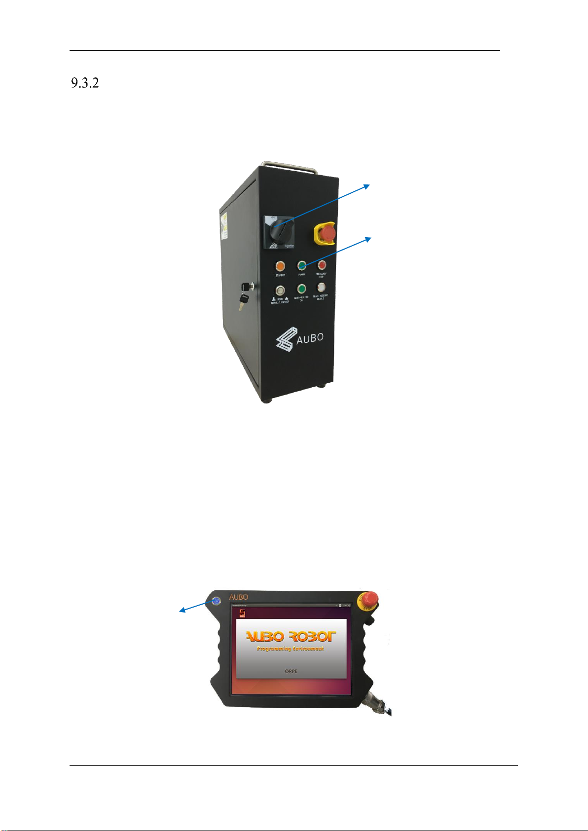
V4.5
©2015-2019 AUBO.All rights reserved. 86
Power on System
Power on I series control box
Connect the cable connector to the AC power outlet, then switch the power from OFF to ON to light the
power indicator.
Figure 9-1 Power switch
Power on the teach pendant and the manipulator
➢ Turn the key switch to the manual mode (manipulator has two working modes: manual mode and
linkage mode. Please read chapter 8.4.4 for more instructions).
➢ Wait for STANDBY lights steady and enters the standby state.
➢ Press start up button on the upper left of the teach pendant for about 1s when the blue light appears.
Robot and the teach pendant power-on at same time and the screen of teach pendant lights up.
➢ The startup button and the state of LED indicator are shown in follow figure.
Figure 9-2 the start button and LED indicator
Power switch
Power indicator
The start button and LED
Page 91
V4.5
©2015-2019 AUBO.All rights reserved. 87
Power off the manipulator
Power off order: First, power off the robot and the teach pendant, then power off the control box.
a) Power off the manipulator and the teach pendant.
⚫ Normal exit: click the shutdown button on the upper right of the screen .
⚫ Mandatory shutdown: press and hold the startup button on the upper left of the teach pendant for
about 5s to turn off the blue light, then the teach pendant and the manipulator will power off.
b) Power off the control box.
Turn the power switch of the control box to OFF position.
1. Unplugging the power cord directly from the wall outlet to show down the system
may result in damage to the robotic file system, which may result in robot malfunction.
2. Ensure to unplug the power cord after power off the whole robot system!
Start system quick
Before starting the robot system, please make sure that the robot body and control box are installed
correctly.
➢ Rotate the control cabinet power switch to the ON state, wait for the power indicator and standby
indicator to light up;
➢ Press the switch button on the teach pendant to start AUBORPE, and the text will be displayed on the
interface;
➢ A pop-up window appears on the touch screen to indicate that the system enters the initialization
interface;
➢ Set the collision level, select and determine the tool;
➢ Please stand outside the reach of the robot body (work space);
➢ Click the start button to release the robot brake system. At this time, the robot body vibrates and
clicks, indicating that the robot system has been started and enters the state to be programmed.
Page 92
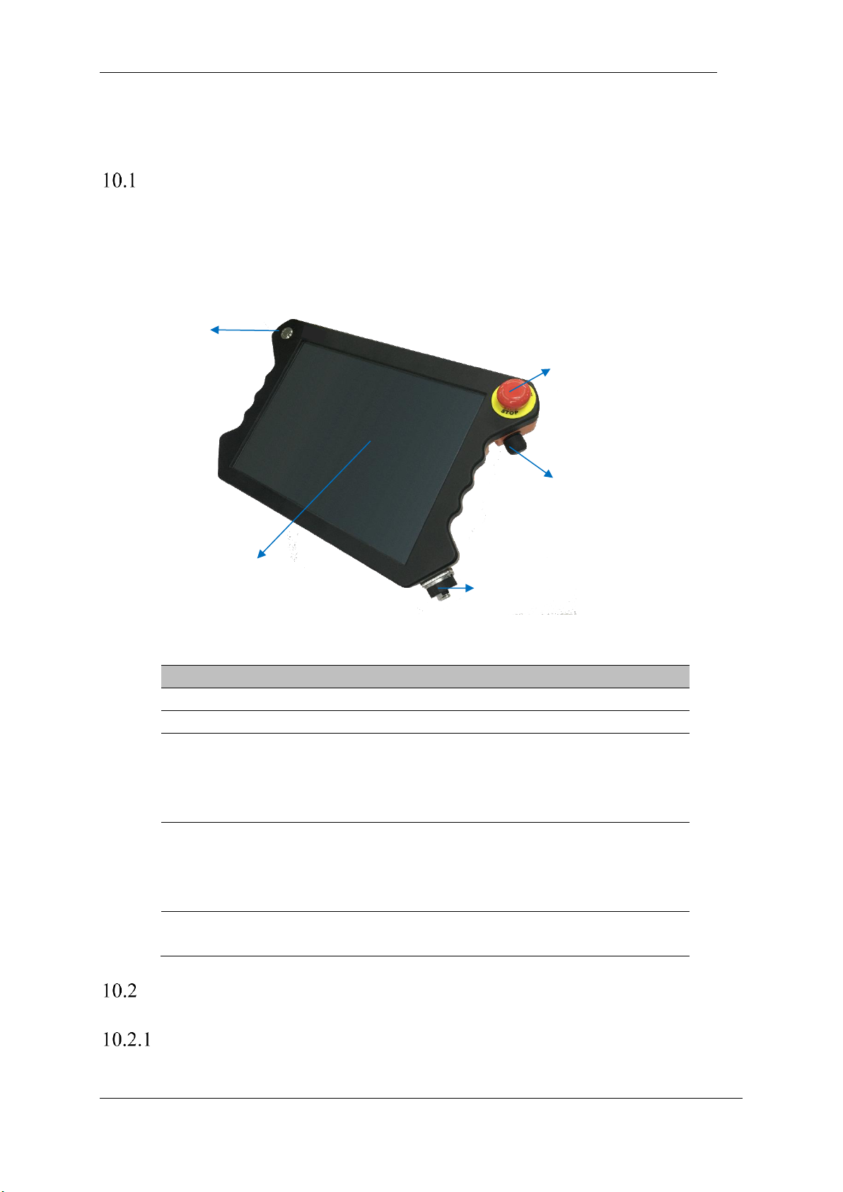
V4.5
©2015-2019 AUBO.All rights reserved. 88
10. TEACH PENDANT
Instruction
The teach pendant is an important component of AUBO-i10 robot. Users can acquire information of the
robot through the teach pendant, User also can control the manipulator to move and perform simple
programming through the teach pendant.
Figure 10-1 Overview of the teach pendant
Number
Name
Function
1
switch
Used to enable or disable the teach pendant software.
2
LCD touch screen
Display of robot operation and status information.
3
emergency button
The emergency stop button on the teach pendant can
be used to stop the robot. If you need to return to the
normal mode, you need to rotate the button in the
direction shown on the button.
4
Force control switch
It is a three-position enable switch that can realize the
three-position action of avoiding dangerous OFF
(opening) ⇒ ON ⇒ OFF (pressing). When the switch
is in the ON state, the robot can be dragged to teach.
5
Teach pendant cable
socket
Interface for cable connection to the control box.
Teach Pendant Operation Interface
User login
After the Teach Pendant software is turned on, enter the user disclaimer interface (you can tick the option
Teach pendant connector cable socket
Force control button
Emergency stop button
Power button
LCD touch screen
Page 93
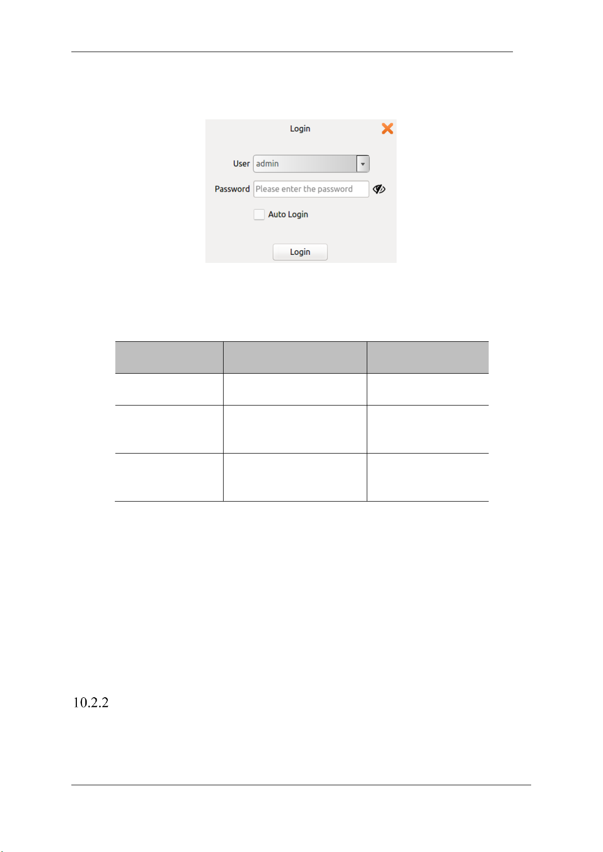
V4.5
©2015-2019 AUBO.All rights reserved. 89
to no longer prompt, and then run the AUBORPE software will no longer appear in this interface), after
clicking through, the user login window will pop up.
Figure 10-2 login interface
Users need to select an account and enter a password before they can log in.
Form 25 User Name Classification
User
Password
Permission limit
Admin (administrator)
The initial password is 1, the
user can modify
Maximum authority,
unlimited
Operator
The initial password is 1, the
user can modify
Safty Settings (10.5) and
update (10.6.6) are not
available
Default (default user,
cannot choose actively)
The default password is 1, the
user cannot modify
Safty Settings (10.5) and
update (10.6.6) are not
available
➢ Username does not support customization
➢ After checking the automatic login, the software will automatically enter the selected user
interface after it is turned on again.
➢ To cancel automatic login or switch user login, you need to click the logout icon in the
upper right corner of the interface.
➢ After determining the logout operation, if there is a running project, it will stop running and
switch to the user login interface.
➢ In the linkage mode, you are advised to select the login user and check the automatic login
option. If it is not checked, the default user is entered.
Initial Interface
After starting the AUBOPE, The following window will pop up:
Page 94
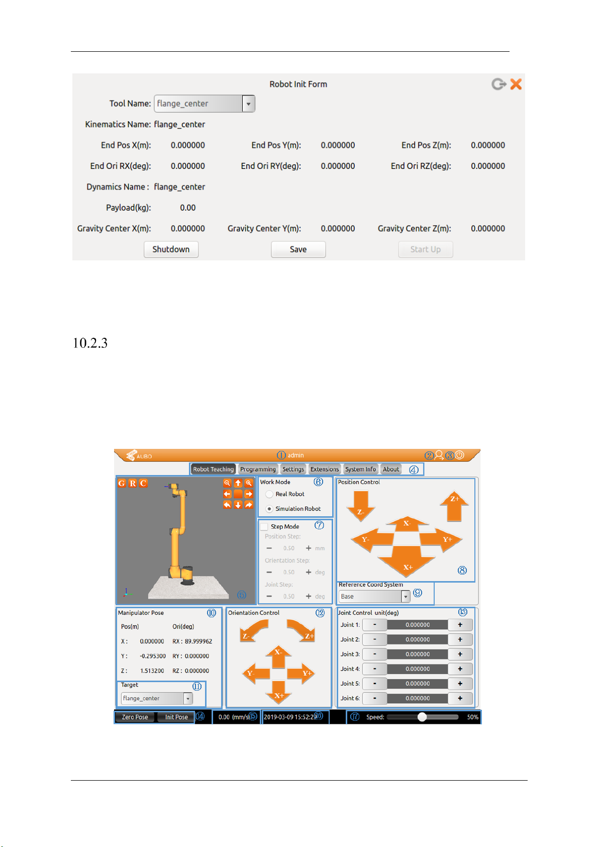
V4.5
©2015-2019 AUBO.All rights reserved. 90
Figure 10-3 Initial Interface
User can select the specified tool flange center as the tool name.
Click save-> start up button, then enter the teaching interface
Robot Movement Control
Robot Teaching User Interface
The Robot Teaching panel is used for the robot teaching operation. User can move the robot by clicking icon
on the panel and get feedback information of movements from the panel. This section mainly focuses on the
Robot Teaching panel.
Figure 10-4 Robot Teaching interface
The Robot Teaching user interface consists of 17 components:
Page 95
V4.5
©2015-2019 AUBO.All rights reserved. 91
Number
Name
1
Currently logged in user
2
Logout button
3
Software close button
4
Menu bar options
5
3D simulation model
6
Work mode option
7
Step mode setting
8
Position control
9
Coordinate system selection
10
Robot arm position and orientation
parameter display
11
Target selection
12
Attitude control
13
Joint control
14
Zero pose and initial pose button
15
Speed display
16
Date and time display
17
speed control
1 Currently logged in user
The section of the software header bar displays the name of the currently logged in user. You can use the
logout button to switch the logged in user. For details, see10.2.1User login.
2 Logout button
Log out of the currently logged in user account by clicking this button.
3 Software shut down button
Click to shut down the software.
4 Menu
Figure 10-5 User interface menu
Press on the menu would select the menu item. The selected menu renders a light text on a dark
background.
Page 96
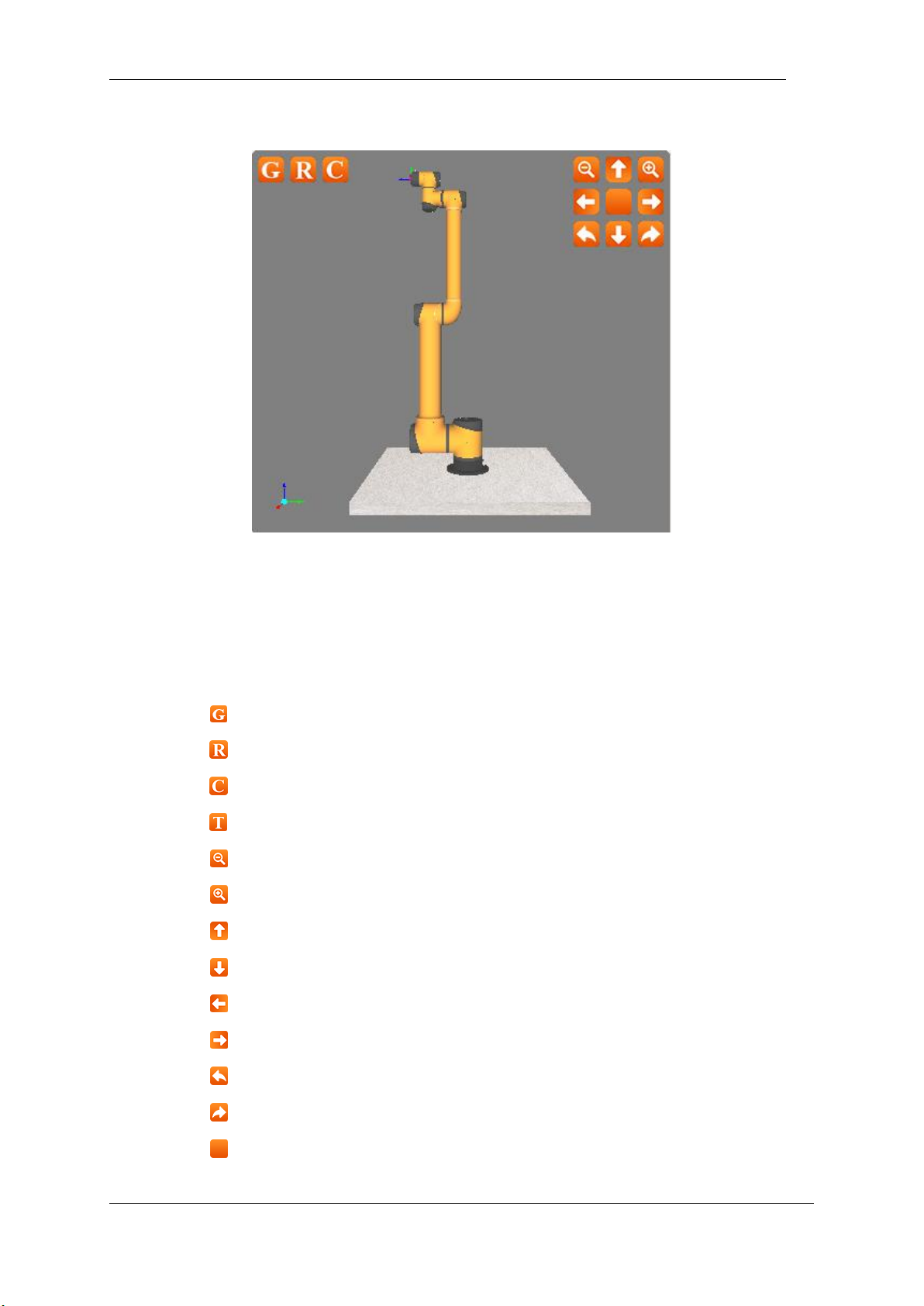
V4.5
©2015-2019 AUBO.All rights reserved. 92
5 Robot 3D display window
Figure 10-6 Robot 3D display window
➢ Robot 3D display window verifies the user-written project without the real robot.
➢ The buttons on the upper left corner are used to observe 3D model. From left to right: rotating
counterclockwise along Z axis, rotating clockwise along Z axis zoom in, and zoom out.
➢ The function of the icons as follow:
:Base plane: click to hide the base reference plane in the simulation interface
:Actual waypoint model: click to hide
:User coordinate; click to hide
:Target waypoint model: click to hide
:Zoom out button
:Zoom in button
:Pan up button
:Pan down button
:Pan left button
:Pan right button
:Turn clockwise
:Turn counterclockwise
:Reset button
The simulation modet can also be used to validate control programs before applying on the real robot.
Page 97
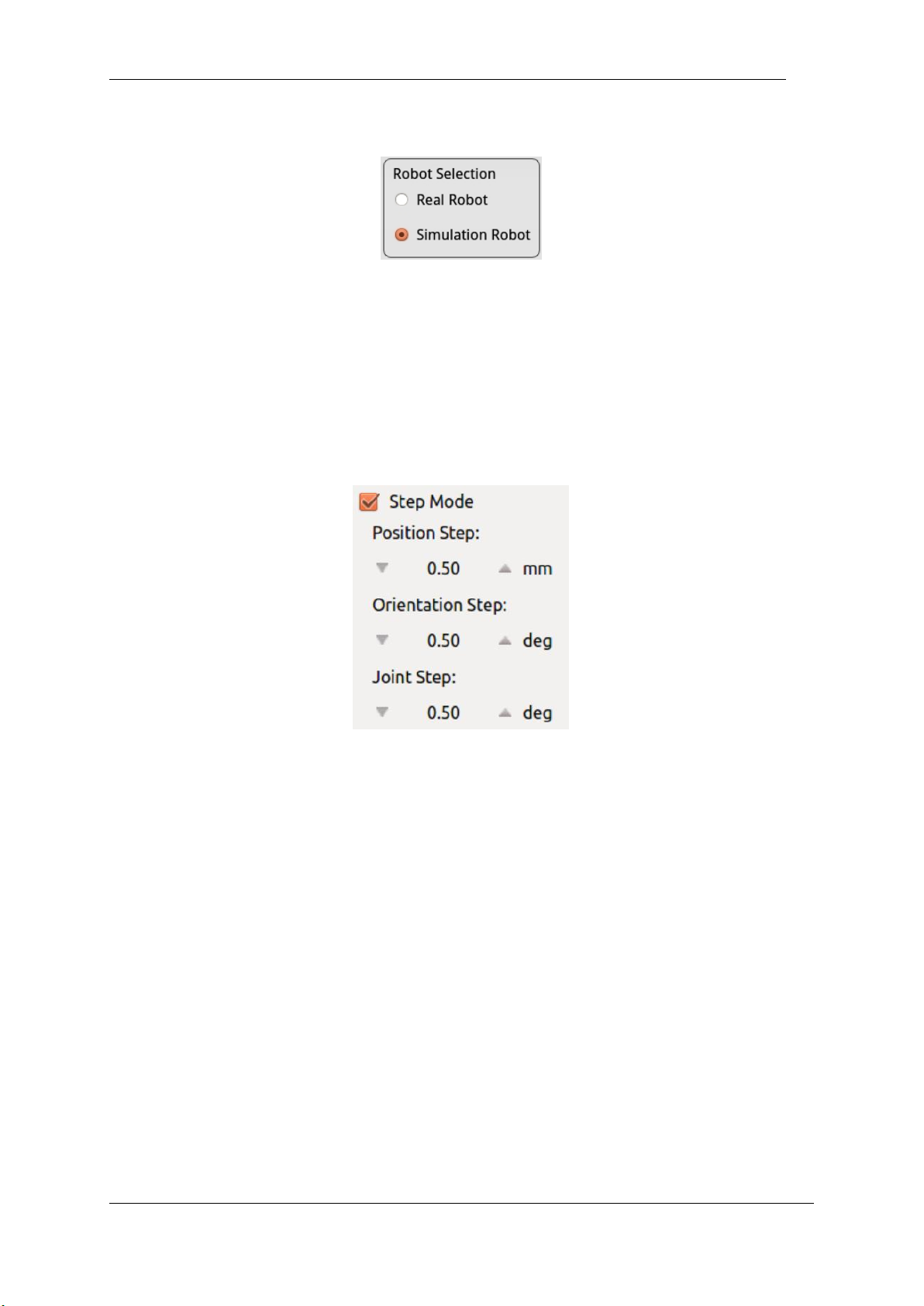
V4.5
©2015-2019 AUBO.All rights reserved. 93
6 Simulation/real control switch button
Figure 10-7 Robot mode selection.
➢ When "Real Robot" is selected, the teach pendant will control the robot manipulator in real time.
➢ When "Simulation Robot" is selected, the 3D manipulator model operates but the real robot won’t
move. To finish a program, users can test whether the procedure is right, firstly, by simulation to
improve the safety of the robot's procedure.
7 Step Mode Control
Figure 10-8 Step mode control.
To improve the control accuracy and flexibility, it is necessary to increase the step mode control to allow the
controlled variable change precisely in a stepwise manner.
➢ Use step control mode by activating step mode.
➢ Click the button on both sides of input box to adjust the robot’s step length.
➢ Position step indicates the step length of the end position movement, unit: mm, range:0.2-10.00mm
➢ Orientation step indicates the step length of the end pose movement, unit: deg, range:0.1-10.00deg
➢ Joint Step indicates the step length of the joint movement angle, unit: deg, range:0.1-10.00deg
➢ Step mode control is valid to control the end position/orientation and joints only.
8 Position control
The end of manipulator is based on the base coordinate system, the end coordinate system or the userdefined coordinate system to control robot movements. The end of manipulator can teach under different
coordinate systems.
Page 98
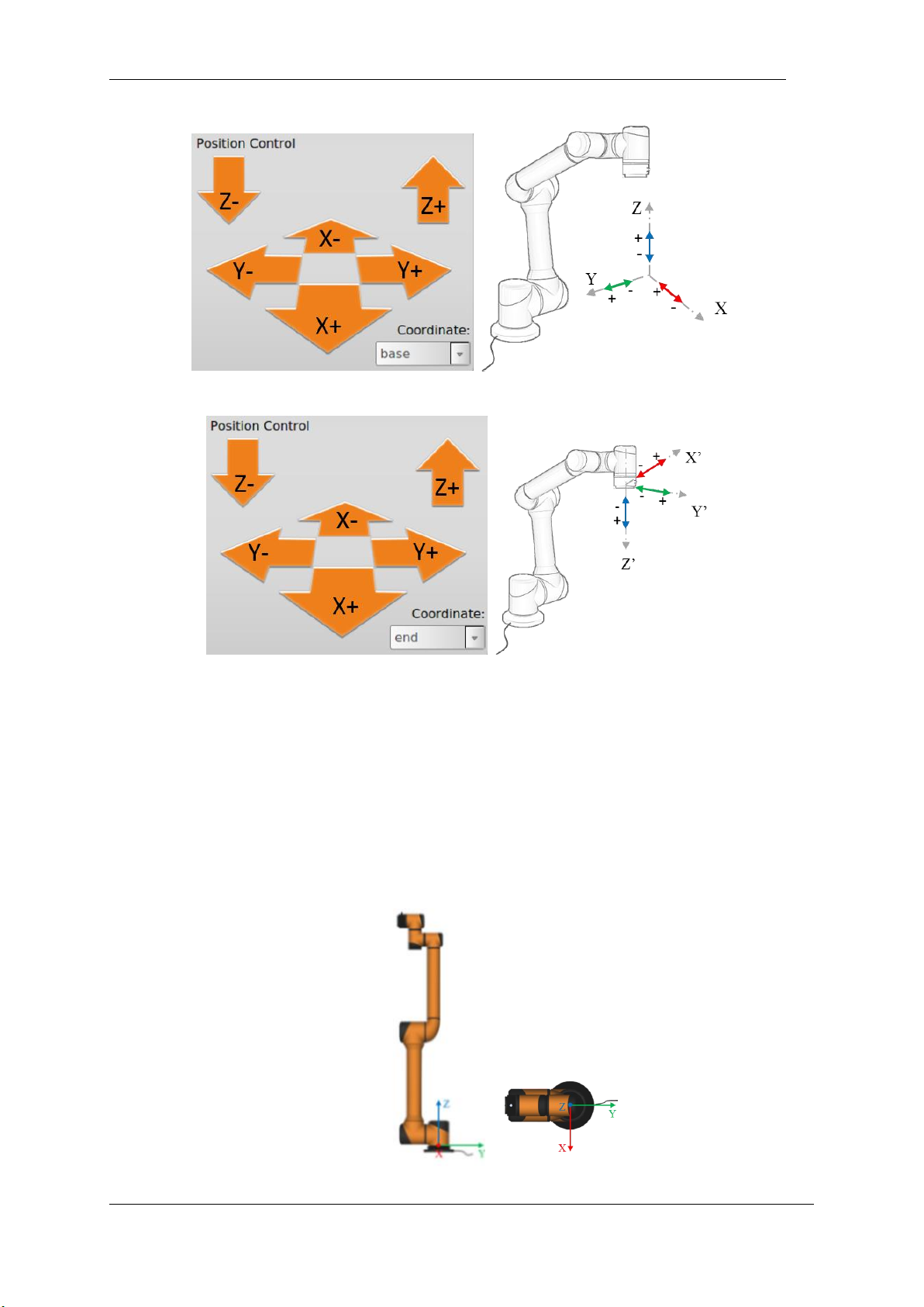
V4.5
©2015-2019 AUBO.All rights reserved. 94
Figure 10-9 Position control(base)
Figure 10-10 Position control(end)
9 Coordinate system
The user can control the motion state of the robot based on the base coordinate system, the end coordinate
system, and the user-defined coordinate system.
base
Select the base coordinate system (base) to control the robot on the teach pendant interface, and the robot
will move according to the coordinate system as shown below.
Figure 10-1 base
Page 99
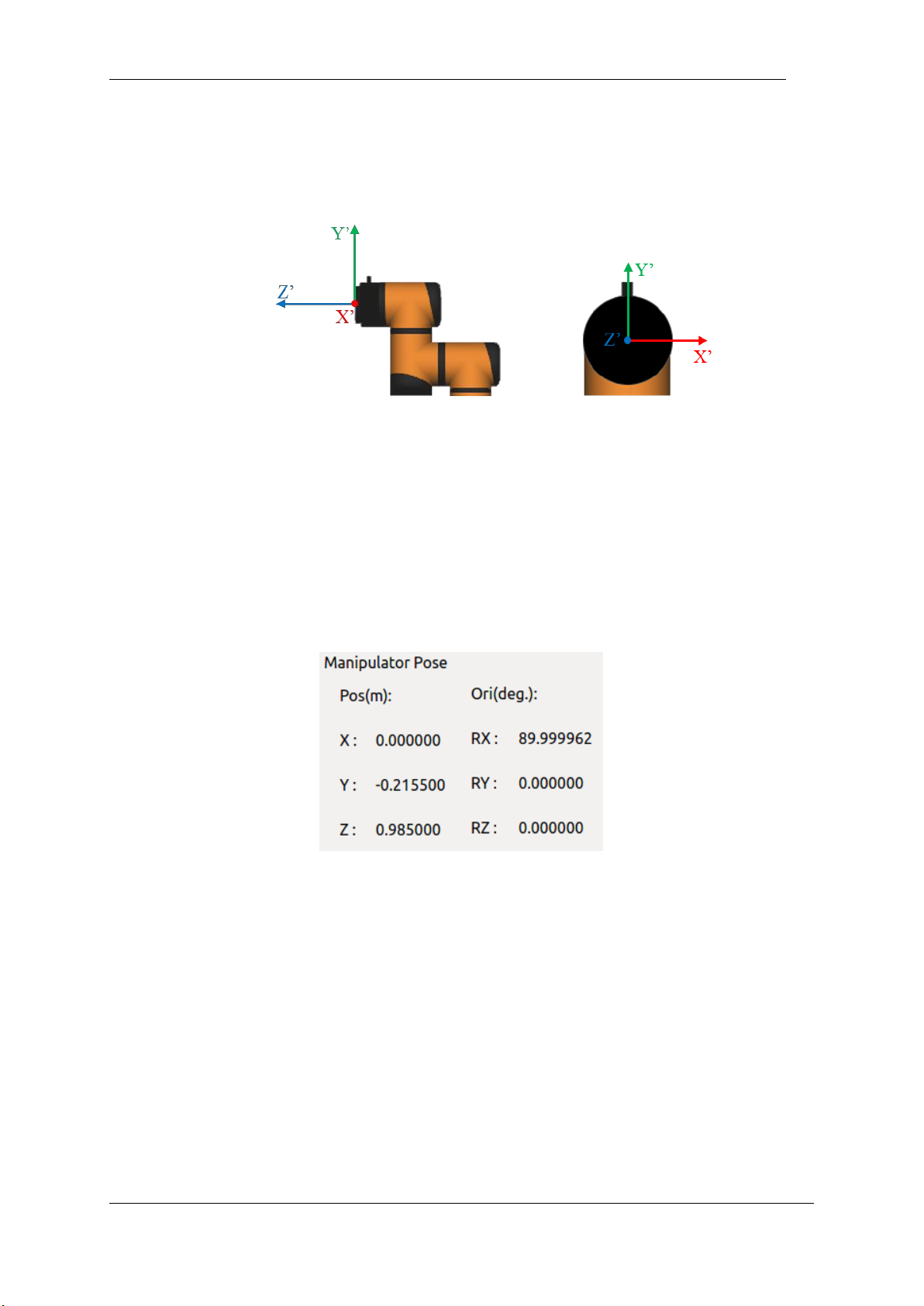
V4.5
©2015-2019 AUBO.All rights reserved. 95
end
Select the end coordinate system (end) on the teach pendant interface to control the robot. The robot will
move according to the coordinate system as shown below.
Figure 10-2 end
9 User-defined coordinate system
The user-defined coordinate system requires the user to set the coordinate system details according to the
actual situation. For details, please refer to the 10.4.3 coordinate system calibration section. After the
setting is completed, the coordinate system name can be selected through the drop-down menu of the teach
pendant interface.
10 Robot real-time status parameter display
Figure 10-11 Pose and position information.
The X, Y, Z coordinates indicates the coordinate of tool flange center (Selected tool coordinate system,
base coordinate system, end coordinate system and user-defined coordinate system). The W, X, Y, Z are
represented to end pose quaternions.
End pose is represented by quaternions, which can also be transformed as other representations (for
example, Euler angles).
11 Target selection
The Target Selection drop-down menu provides the option to display the pose position for the flange center
of gravity (default) or the specified tool end function. Users can add drop-down menu tool options via the
10.4.2 Tools Calibration section.
Page 100
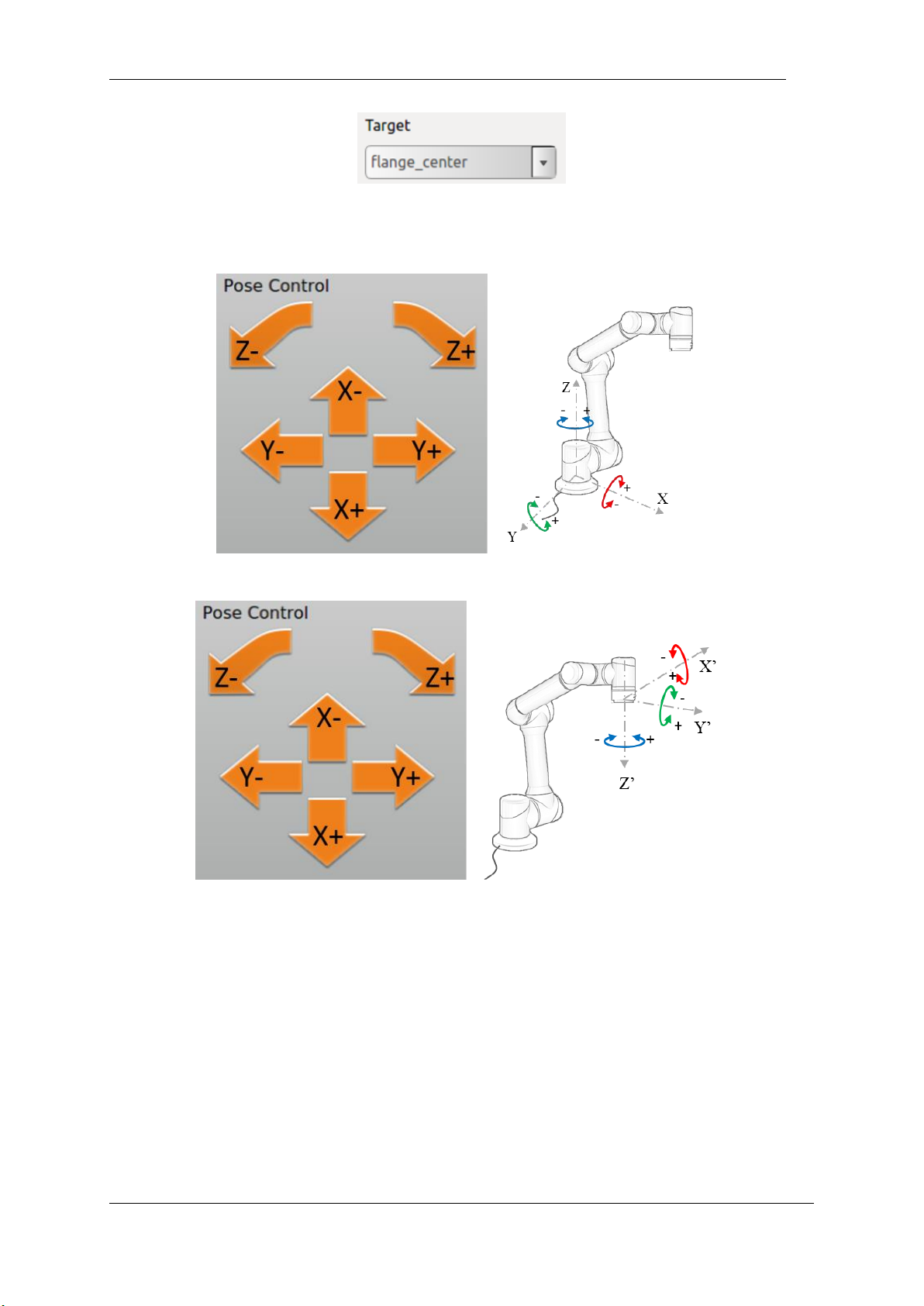
V4.5
©2015-2019 AUBO.All rights reserved. 96
Figure 10-3 Target selection
12 Orientation Control
Figure 10-12 Orientation Control (base)
Figure 10-13 Orientation Control (end)
 Loading...