

Page 1
TH131 & TH133
User Guide
Electronic Thermostat
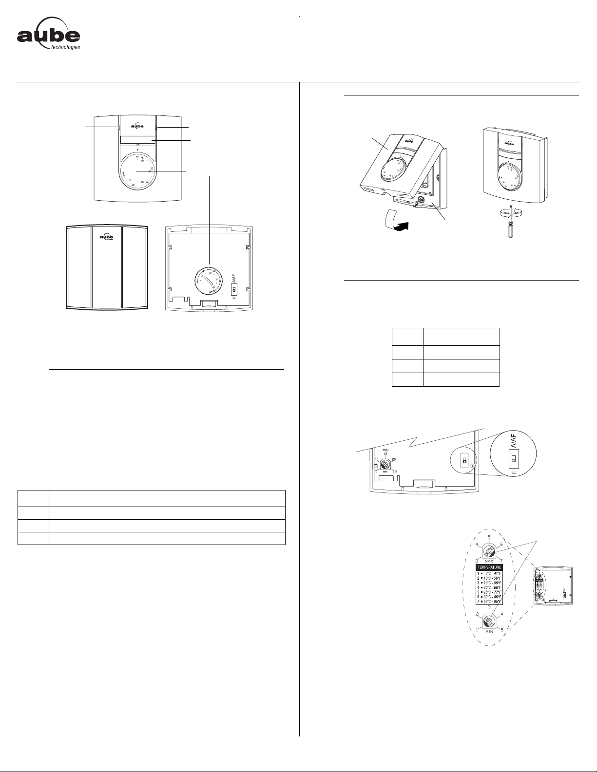
TH131
Pilot wire indicator
(Europe only)
TH133
Front View
NOTE: Even if the following illustrations show the TH131 model only,
they can also apply to the TH133 model.
n
This user guide covers the following thermostat models:
The TH131 model is designed for residen tial applications, whereas
the TH133 model is designed for public areas as its controls are hidden and thus protected against unauthorized access. Both models
can be configured for the following applications:
Description
• TH131 A/F/AF
• TH133 A/F/AF
Heating indicator
On/Off switch
Temperature
selection dial
Rear View
2.
o
NOTE: Keep the thermostat's air vents clean and free from obstructions.
p
Installation
Control Module
Power Base
3.
Configuration
3.1 Application Types
Type Switch Position
AUP (A/AF)
1.
Position the switch, on the back of the control module, according to
your application.
AF UP (A/AF)
FDOWN (F)
Type Application
A Controls the ambient (room) temperature
F Controls the floor temperature
AF Controls the ambient temperature and limits the floor temperature
TH131 & TH133 400-131-002-C 1/11/06 1/2
3.2 Minimum and Maximum Limits (TH131 only)
Use the two potentiometers on the
back of the control module to set
the minimum and maximum temperature limits. Depending on your
application, the potentiometers
limit the following temperature:
ambient temperature (A)
floor temperature (F or AF)
Use a flat-tip screwdriver to rotate
the potentiometers until the notch
points to the desired temperature
limit.
notches
Page 2
q
Operation
4.1 Temperature Adjustment
TH131
Use the dial on the front of the thermostat to set the desired temperature.
NOTE: If the dial is placed at a temperature beyond the high or low
temperature limit, the temperature will be maintained at that limit (see
section 3.2).
TH133
Remove the control module from the base and use the dial on the
back of the control module to set the desired temperature.
4.2 On/Off Switch (TH131 only)
Use the On/Off switch to turn the thermostat Off when it is not used
(e.g., in the summer).
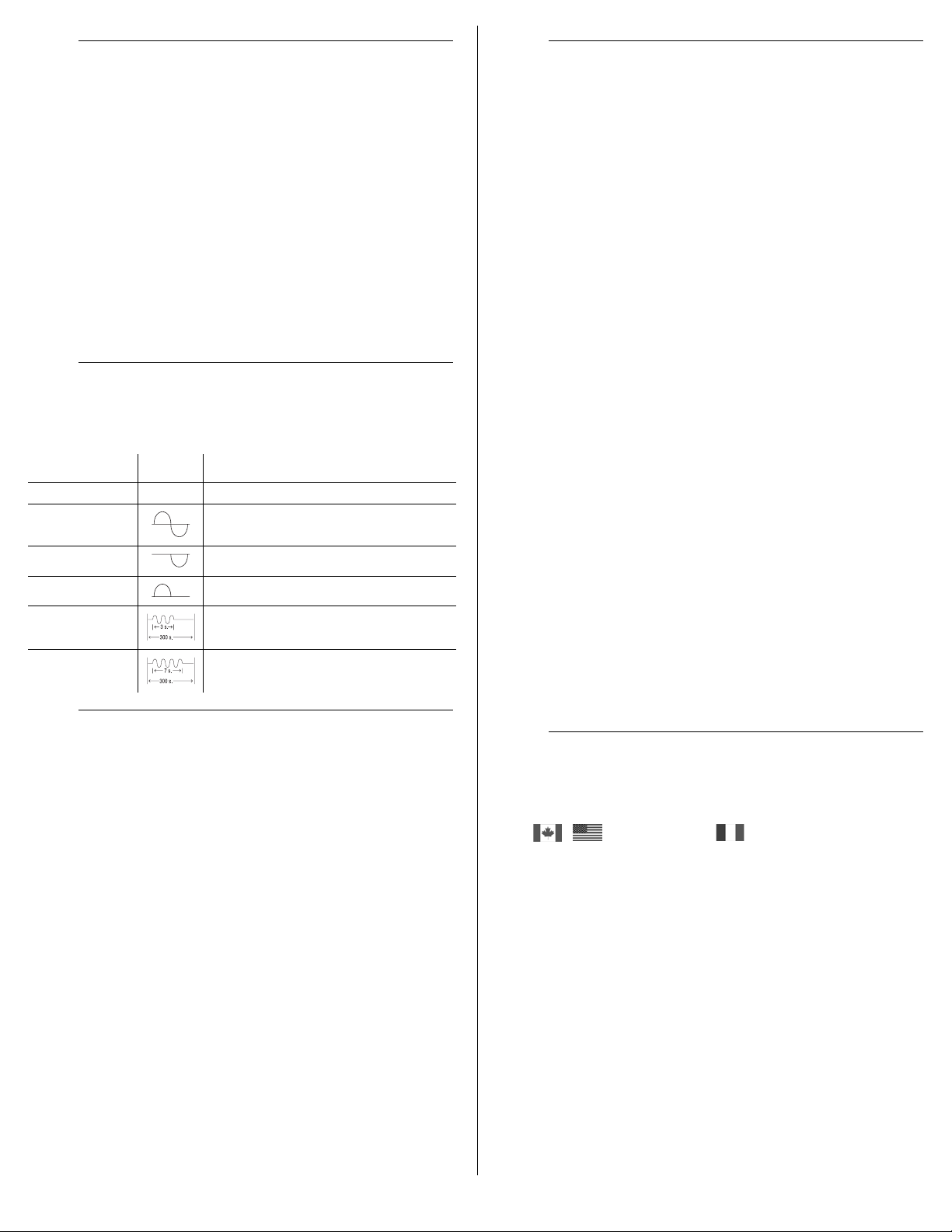
r
TH131 accepts the six following pilot wire orders when installed on a
230 V power base.
s
Setpoint range: 7°C, 15°C to 35°C (45°F, 59°F to 95°F)
Minimum temperature limit: 5°C to 25°C (41°F to 77°F)
Maximum temperature limit: 15°C to 35°C (59°F to 95°F)
Accuracy: ± 0.2°C (0.36°F)
Storage: -20°C to 50°C (-4°F to 120°F)
Heating cycle length: 15 minutes
Software: Class A
Controller: Electronic
Size (H/W/D):
• TH131: 78.9 x 78.9 x 16.3 mm (3.1 x 3.1 x 0.64 in.)
• TH133: 78.9 x 78.9 x 18 mm (3.1 x 3.1 x 0.71 in.)
Pilot Wire Orders (Europe only)
ORDER SIGNAL DESCRIPTION
Comfort No signal Maintain temperature at setpoint
Reduced setpoint
(3.5k setback)
frost protection Maintain temperature at 7°C
Off Stop heating
1k setback Maintain temperature at 1°C below setpoint
2k setback Maintain temperature at 2°C below setpoint
Maintain temperature at 3.5°C below
setpoint
Specifications
4.
;
AUBE TECHNOLOGIES INC. THREE (3) YEAR LIMITED WARRANTY
Aube warrants this product, excluding battery, to be free from defects
in the workmanship or materials, under normal use and service, for a
period of three (3) years from the date of pu rchase b y the con sumer.
If at any time during the warranty period the product is determined to
be defective or malfunctions, Aube shall repair or replace it (at Aube's
option).
If the product is defective,
(i) return it, with a bill of sale or other dated proof of purchase, to
(ii) contact Aube. Aube will make the determination whether the
This warranty does not cover removal or reinstallation costs. This
warranty shall not apply if it is shown by Aube that the defect or
5.
6.
malfunction was caused by damage which occurred while the
product was in the possession of a consumer.
Aube's sole responsibility shall be to repair or replace the product
within the terms stated above. AUBE SHALL NOT BE LIABLE FOR
ANY LOSS OR DAMAGE OF ANY KIND, INCLUDING ANY
INCIDENTAL OR CONSEQUENTIAL DAMAGES RESULTING,
DIRECTLY OR INDIRECTLY, FROM ANY BREACH OF ANY
WARRANTY, EXPRESS OR IMPLIED, OR ANY OTHER FAILURE
OF THIS PRODUCT. Some regions do not allow the exclusion or
limitation of incidental or consequential damages, so this limitation
may not apply to you.
THIS WARRANTY IS THE ONLY EXPRESS WARRANTY AUBE
MAKES ON THIS PRODUCT. THE DURATION OF ANY IMPLIED
WARRANTIES, INCLUDING THE WARRANTIES OF
MERCHANTABILITY AND FITNESS FOR A PARTICULAR
PURPOSE, IS HEREBY LIMITED TO THE THREE-YEAR
DURATION OF THIS WARRANTY. Some regions do not allow
limitations on how long an implied warranty lasts, so the above
limitation may not apply to you.
This warranty gives you specific legal rights, and you may have other
rights which vary from region to region.
If you have any questions about the product installation or operation,
or concerning the warranty, contact us at:
Warranty
the place from which you purchased it, or
product should be returned, or whether a replacement product
can be sent to you.
Customer Assistance
705 Montrichard
Saint-Jean-sur-Richelieu
Quebec, Canada J2X 5K8
Tel.: (450) 358-4600
Toll Free: 1-800-831-AUBE
Fax: (450) 358-4650
Email: aube.service@honeywell.com
For more information on our products, go to
www.aubetech.com
10 rue Ampère
95500 Gonesse
France
Tel.: 33 (0) 1 34 07 99 00
Fax: 33 (0) 1 34 07 99 19
Email: advaube@comintes.com
7.
8.
TH131 & TH133 400-131-002-C 1/11/06 2/2
Page 3

PB130
Installation Instructions
230 V Line Voltage Power Base
The PB130-230 power base is used to power a TH13x Series control
module. The resistive load must not exceed 3450 watts (NI) @
230 VAC (15 A).
n
Parts
n One (1) PB130-230 power base
o One (1) floor sensor (for AF and F control modules only)
p One (1) wall plate (optional, in certain countries)
o
Turn off power to the heating system at the main power panel to avoid
electrical shock. Installation should be carried out by an electrician.
All work must conform to the applicable country standards for
This thermostat should be connected on a circuit equipped with
For a new installation, choose a location about 1.5 m above the
For electric baseboards, convectors and fan-forced heaters, the
The thermostat must be installed on an inside wall.
Avoid locations where there are air drafts (top of staircase, air
p
Model: PB130A-230
Supply: 230 VAC, 50 Hz
Load: 15 A maximum (resistive only)
Power: 3450 Watts (NI) @ 230 VAC
Conformity: EN60730-2-9 / EN50081-1 / EN50082-2
Storage: -20°C to 50°C
Protection: Class 2
Protection degree:IP21
Automatic action: Type 1.B
Environment: Normally polluted
Size (H•W•D): 2.95 x 2.95 x 0.55 in. (75 x 75 x 14 mm)
NOTE: The terminals are designed to handle a cross-section of wire
measuring 0.33 to 3.1 mm
q
Guidelines
electrical installations and wiring.
a fuse or a circuit breaker. It must be installed on a certified
electrical box.
floor.
thermostat must be installed facing the heating system.
outlet), dead air spots (behind a door), direct sunlight or
concealed chimneys or stove pipes.
Technical Specifications
2
.
Procedure
n Remove the screw holding the
control module to the power base
and lift the lower part upwards.
The screw cannot be completely
removed.
o Before making the connections, make sure
that the base covers the electrical box
entirely. If not, install a wall plate at the
1.
back of the base as shown.
p Connect the wires:
2.
3.
• Power:
Terminals 1 & 5
• Load:
Terminals 2 & 4
see note 1
• Pilot Wire:
Terminal 3
see note 2
• Floor sensor:
Terminals 6 & 7
(no polarity)
see note 3
Note 1 If a contactor is used between the thermostat and the load,
install a snubber at the contactor’s coil terminal to ensure
the proper operation of the thermostat.
Note 2 This connection is required on some models only.
Note 3 For the proper operation of the thermostat, the floor sensor
must be centered between two heater wires having a
maximum temperature of 80°C. The floor sensor wire must
not cross any heater wire or be placed close to it.
r Push wires into the electrical box and
secure the base to the electrical box
anchorage. The head of the screw
must be less than 2 mm thick.
s BEFORE installing the control
module onto the base, set the
configuration switches (if any)
on the control module (refer to
4.
the user guide).
WARNING: This power base must be used only with 15-minute
heating cycles. If your control module has a selector switch for
choosing the heating cycle, ensure that the switch is correctly set.
t Return power to the heating system.
PB130 400-130-001-E 19/9/05 1/1
 Loading...