

Page 1
CT240 Telephone
Controller
Installation Instructions and User Manual
1 . Introduction
The CT240 telephone controller is designed to remotely control your
home’s thermostat. It is possible to command a temperature
decrease (Unoccup ied) duri ng a prol onged a bsenc e or a tempera ture
increase (Comfort) before you return home.
Depending on your thermostat’s operating characteristics, it either
connects to the Aube output (for most Aube models) or to the auxiliary output.
When the auxiliary output is not used to control a thermostat, it can
be used to simultaneously control a load such as a water heater,
lighting, etc.
)LJXUH
ЛнкЯрЮпϫКсансдатϫ
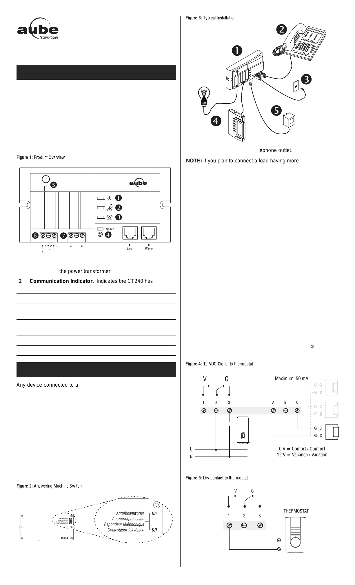
)LJXUH
ПфлдЮЬзϫДйопЬззЬпдкй
n Mount the CT240 near a telephone outlet.
NOTE: If you plan to connect a load having more that 30 volts on the
auxiliary output, the CT240 must be installed inside a certified electrical box.
o OPTIONAL. Connect your phone (or answering machine) to the
PHONE connector of the CT240.
p Connect one end of the telephon e cable to the LI NE connecto r of
the CT240 and the other end to the telephone outlet in your
home.
q Connect the thermostat and load. Both outputs work simulta-
neously.
NOTE: Refer to your thermostat’s electrical specifications (telephone
interface) for the connection requirements.
1 Power Indicator. Indicates the CT240 i s powered on. T o turn
it off, unplug the power transformer.
2 Communication Indicator. Indicates the CT240 has
answered and is awaiting a command.
3 Ring Indicator. This indicator flashes when the phone rings.
4 Reset. This button can be used to reset the CT240 to its
default values. Seesection 3.3.
5 Manual Output Activation Button. Can be used to manually
switch the relay status.
6 Auxiliary Output. See section 2.
7 12 VDC Output. See section 2.
2. Installation
Any device connected to a telephone line must conform to the country's standards. The CT240 telephone controller meets:
• FCC68 standards for installation on the North American network.
• FDTBR21 standards for installation on the European network.
2.1 Included Parts
• If your thermostat req ui r es a 1 2 VDC s ig nal to sw it ch to Vacation setpoint, use the ABC output (FIGURE 4):
A and C terminals:
• 0 VDC in Comfort mode
• 12 VDC in Vacation mode
NOTE: 50 mA max. for parallel connection of Aube thermostats.
• If your thermostat requ ires a dry c ontac t to s witch t o the Vacation setpoint, use the 123 output (FIGURE 5):
• Load = terminals 2 and 3 (NC) (open = Vacation)
• Thermostat = terminals 1 and 2 (NO) (closed = Vacation)
r When all connections have been made, connect the power
transformer to the 9 V outlet of the CT240 and the other end to
the wall electrical o utlet. The p ower indicator l ight is ON when
the circuit is powered.
)LJXUH
ϼ Ͻ ϫ СЏЎϫ О двй Ьзϫ пкϫ пганикопЬп
• One CT240 telephone controller
• One power transformer 120 V (North America) or 250 V (Europe)
• One 5 m (16 foot) telephone cable
NOTE: I f you are using an answer ing mac hine, p osition the answ er-
ing machine switch to ON before installing the CT240.
Make sure that your ans weri ng mach ine answers aft er a mini mum of
4 rings.
)LJXUH
ЌйотандйвϫИЬЮгдйаϫ ОтдпЮг
)LJXUH
Џнфϫ ЮкйпЬЮпϫ пкϫ пг а никопЬп
1/2 400-240-001-A
Page 2
3. Operation
NOTE: The CT240 will automatically hang up if no key is pressed
during the 30 seconds following the CT240 answering a call.
Default values:
• Access code = 1234
• Number of rings = 4
3.1 With or Without an Answering Machine
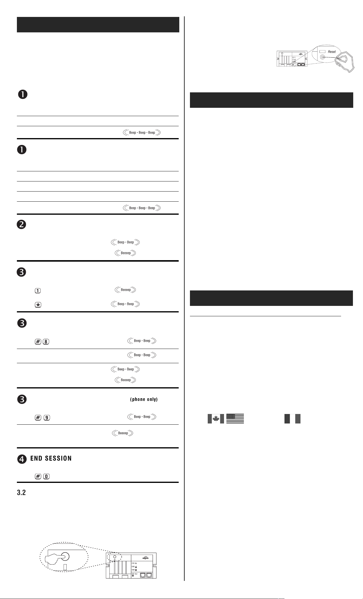
3.3 Reset to default values
Insert a pointed object (e.g. paper clip) in the hole located under the
Reset light. The light will flash 3 times to indicate that the CT240 has
been reset:
• number of rings: 4
• access code: 1234
• Output status:
ABC: Terminals A and C: Comfort
123: Terminals 1 and 2: opened, Terminals 2 and 3: closed
BEGIN A SESSION (without answering machine)
Dial your phone number
Wait for the number of rings...
CT240 answers
BEGIN A SESSION (with an answering machine)
Dial your phone number
Let it ring once and hang up
Wait 10 seconds...
Dial your phone number again within the next 30 seconds
CT240 answers (1st ring)
ENTERYOURACCESSCODE
Enter your 4-digit access code
(default: 1234)
OUTPUT STATUS/MODIFY STATUS
Press for output status
Press to change status
MODIFY THE ACCESS CODE
Press
Enter your new 4-digit access code
Enter the access code again
MODIFY THE NUMBER OF RINGS
SKRQH RQ O\
Accepted
Error
Comfort
Vacation
Accepted
Error
4. Technical Specifications
Power supply: 9 VAC / 60Hz (50 Hz Europe)
Output (ABC): 0 VDC = Comfort mode / 12 VDC = Vacation mode
Maximum load for parallel connection of Aube thermostats: 50 mA
Auxiliary output (123): SPDT with following capacity:
• 5 A / 30 VAC inductive / Power Factor: 0.4
• 10 A / 30 VAC resistive (if installed in a certified electrical box)
• 10 A / 240 VAC resistive (if installed in a certified electrical box)
• 1/2 HP / 120 VAC motor (if installed in a certified electrical box)
• 1 HP / 240 VAC motor (if installed in a certified electrical box)
Protection: Class II
Access code (default): 1234
Number of rings (defaul t):4 rings
Memory protection: In case of power failure, access code and out-
put status are protected.
Phone certification standard:
• FDTBR21: European telephone network
• FCC68: North American telephone network
Approvals:
• c UL us (North America)
• CE (Europe)
Dimensions (H W D): 2.7 x 5.4 x 1.2 in. (69 x 137 x 31 mm)
5. Warranty
AUBE TECHNOLOGIES INC. THREE (3) YEAR LIMITED WARRANTY
This product is guaranteed against workmanship defects for a threeyear period following the initial date of purchase. During this period,
AUBE Technologies Inc. will repair or replace, at our option and without charge, any defe cti ve prod uc t w hi ch has be en u se d u nde r normal
conditions. The warranty does not cover delivery costs and does not
apply to products poorly installed or randomly damaged following
installation. This warranty cancels and replaces any other manufacturer's express or implied warranty as well as any other company
commitment. AUBE Technologies Inc. cannot be held liable for
related or random damages following the installation of this product.
The defective product as well as the purchase invoice must be
returned to the place of purchase or mailed, prepaid and insured, to
the nearest shipping address.
Press
Enter the number of rings after
which the CT240 will answer
(between 1 and 9)
x the number of
selected rings
END SESSION
Press to end the session
3.2 Manual Output Activation Button
The button, located on the upper-left corner of the CT240, can be
used to manually switch the relay status. This option is not available
while the CT240 is answering a telephone call.
The light is ON when the auxiliary output is in Vacation mode (terminals 1 and 2 closed)
705 Montrichard
Saint-Jean-sur-Richelieu
Quebec, Canada J2X 5K8
Tel.: (450) 358-4600
Toll Free: 1-800-831-AUBE
Fax: (450) 358-4650
service@aubetech.com
For more information on our products,
visit us at www.aubetech.com
10 Ampère Street
95500 Gonesse
France
33 (0) 1 34 07 99 00
33 (0) 1 34 07 99 19
advaube@comintes.com
29/10/2003 2/2 400-240-001-A
 Loading...