

Page 1
PB130-024T
Installation Instructions
24 V Low Voltage Power Base
Introduction
The PB130-024T power base is designed to power a TH13X Series
control module. This low voltage power base can be used to drive a
line voltage load using a relay or connect directly to equipment (such
as a hot water system) using a 24 V signal.
Although the PB130-024T is compatible with most relays, it has been
optimized for use with an Aube relay. Aube offers triac relays (SSR)
such as the RT850 and RT850T (with built-in 24 V transformer), and
electromechanical relays such as the RC840 and RC840T (with builtin 24 V transformer).
Installation Guidelines
Cut power to the heating system at the main power panel to
avoid electrical shock. Installation should be carried out by an
electrician.
Ͽ
For a new installation, choose a location about 5 ft. (1.5 m)
above the floor.
Ͽ
The thermostat should be installed facing the heating system
and on an inside wall.
Ͽ
Avoid locations where there are air drafts (top of staircase, air
outlet), dead air spots (behind a door), direct sunlight or concealed chimneys or stove pipes.
ఄంఐఀ ௌ ௮ఄఉంఇఀ ఐఉఄఏ
ఄంఐఀ ் ௨ఐఇఏఄఋఇఀఐఉఄఏఎ
ఄంఐ ఀ ௮ఄ ఉంఇఀ ఐఉ ఄఏே ఀఇ ఔ ఄఉఎఄఀ ఎఀఊ
Included Parts
n One (1) PB130-024T low voltage power base
o Two (2) anchors
p Two (2) mounting screws
Installation Steps
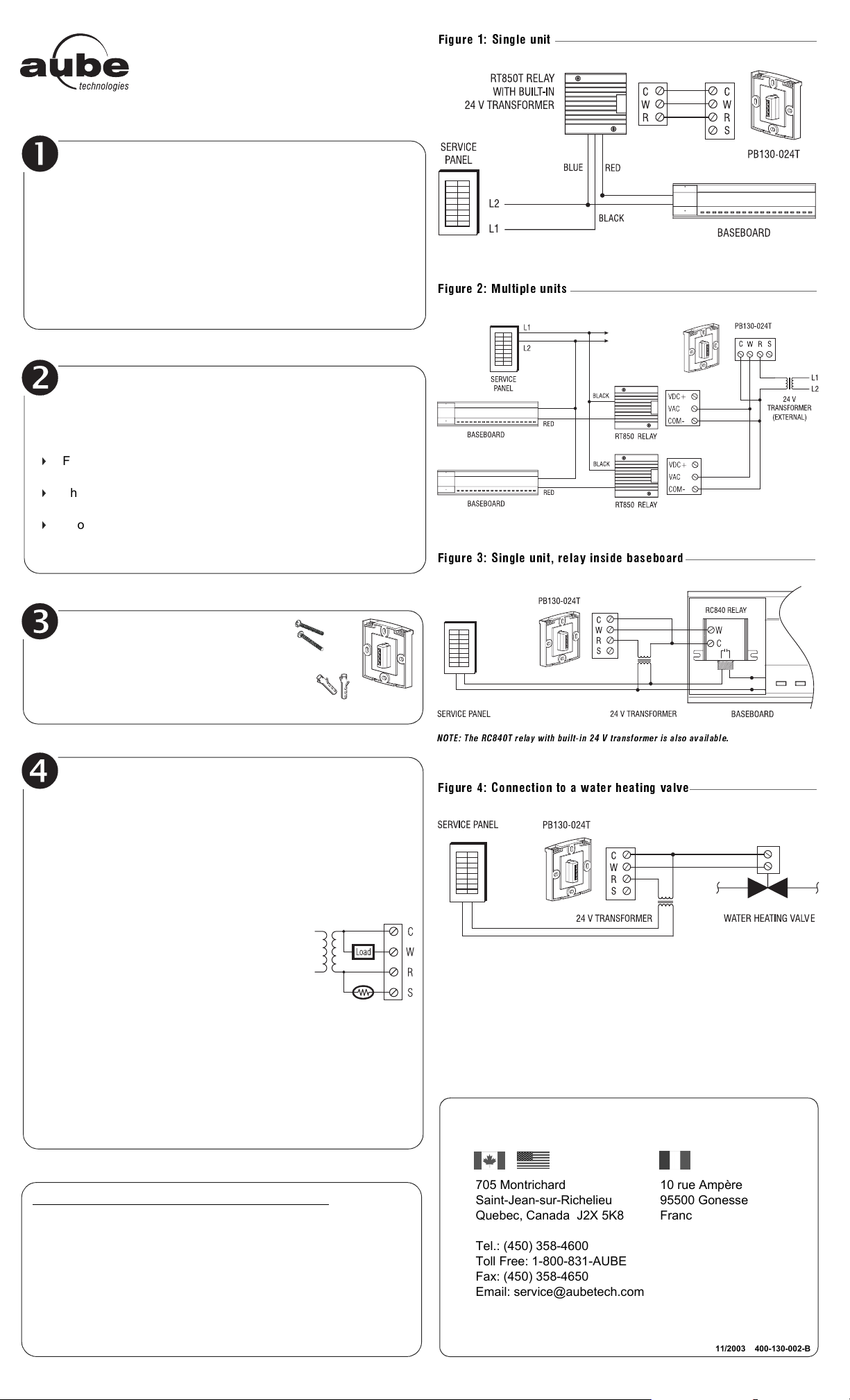
n Connect the base. See the typical wiring diagrams.
a) Electric heating (figures 1, 2 and 3)
• Connect the base to the relay:
• Use a relay with a built-in 24 V transformer or
• Use a relay and an external 24 V transformer.
• Connect the relay to the load (see relay’s instructions).
b) Hot water heating (figure 4)
• Connect the base to the 24 V valve of the
water heating system.
o For a floor heating installation, connect the
floor sensor between the S and R terminals.
p Push the excess wire into the wall and secure the
base using the provided screws and wall anchors.
q Before mounting the control module onto the base, select the
heating cycle, set the switches (if necessary) and mount the
control module. Refer to the control module’s user guide for
more information.
r Once the control module is configured (switches) and installed,
return power to the heating system.
࿑࿒࿗࿈ྣ ࿗ ྣ ࿕࿆ྻྷླ࿗ྣ ྣ ྣ ྰྣ ྵྷྣ ࿙ྣ ྣ ྣ ྣ ྱ
ఄంఐఀ ఊఉఉఀఏఄఊఉఏఊ ఒఏఀఃఀఏఄఉం ఇఀ
Technical Specifi cations
Maximum load: 0.5 A / 24 VAC
Operating temperature: 32°F to 122°F (0°C to 50°C)
Storage: -4°F to 122°F (-20°C to 50°C)
Size (H•W•D): 2.94 x 2.94 x 0.53 in. (74.6 x 74.6 x 13.3 mm)
Wire gauge: 14 to 22 AWG
If you have any questions concerning the PB130-024T low
voltage power base, call our technical support team at:
AUBE TECHNOLOGIES INC. TWO (2) YEAR LIMITED WARRANTY
This product is guaranteed against workmanship defects for a two-year period following
the initial date of purchase. During this period, AUBE Technologies Inc. will repair or
replace, at our option and without charge, any defective product which has been used
under normal conditions.
The warranty does not cover delivery costs and does not apply to products poorly
installed or randomly damaged following installation. This warranty cancels and replaces
any other manufacturer's express or implied warranty as well as any other company
commitment.
AUBE Technologies Inc. cannot be held liable for related or random damages following
the installation of this product. The defective product as well as the purchase invoice
must be returned to the place of purchase or mailed, prepaid and insured, to the
following address.
705 Montrichard
Saint-Jean-sur-Richelieu
Quebec, Canada J2X 5K8
Tel.: (450) 358-4600
Toll Free: 1-800-831-AUBE
Fax: (450) 358-4650
Email: service@aubetech.com
For more information on our products, visit us at:
www.aubetech.com
10 rue Ampère
95500 Gonesse
France
33 (0) 1 34 07 99 00
33 (0) 1 34 07 99 19
advaube@comintes.com
14/11/2003 400-130-002-B
Page 2
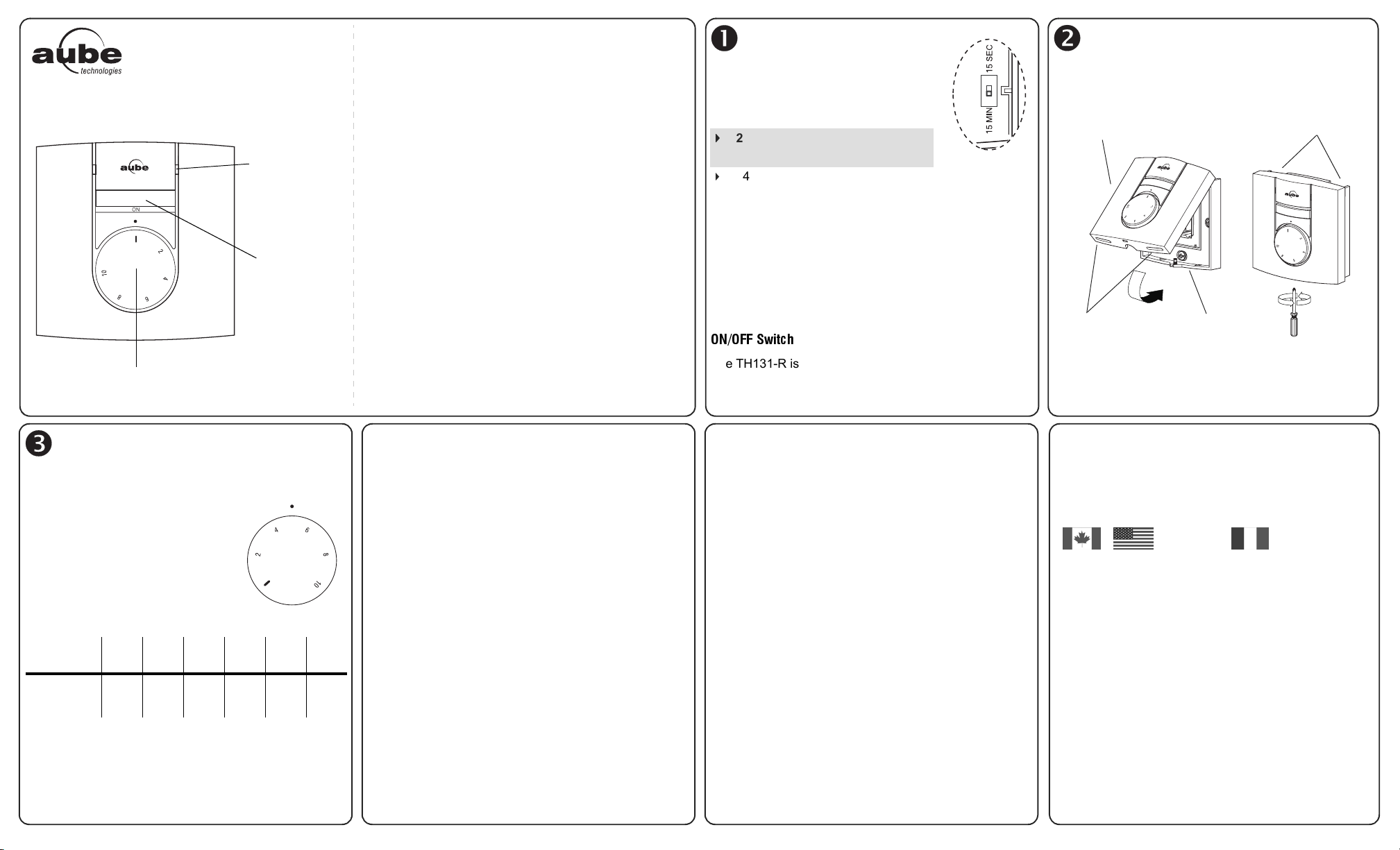
Regulator TH131-R
Heating
Command
Indicator Light
Power Selection Dial
ON/OFF
Switch
Introduction Configure the Switch Install the Control Module
User Guide
Control Module
Thank you for choosing Aube’s TH131-R regulator.
The TH131-R is specially designed to control an electric
floor heating installation, a baseboard or a convector.
The TH131-R regulator operates like a dimmer switch to
allow you to easily adjust the amount of power sent to
your heating system.
This control module can be used with a line voltage power
base (230 V European models) or a low voltage power
base (24 V) combined with an electromechanical or triac
relay.
Operation Technical Specifications
Located in the lower-right corner of the
control module, this switch is used to
select the heating cycle based on the
power base.
230 V LINE VOLTAGE BASE
ALWAYS 15 minutes
Ͽ
24 V LOW VOLTAGE BASE
•15 MIN
Use with a triac or electromechanical relay.
Recommended for mechanical actuated system
(water heating using a solenoid valve, etc.) or a
fan-forced heater.
• 15 SEC
Use only for installations with SSR TRIAC relay.
Recommended for electric heating (baseboards,
convectors, etc.).
Align the bracket tabs on the control module with the
holes located on the power base and secure using the
screw.
Control Module
Air Vents
ࠂࠁߢࠂ߹߹ߓ ࠆࠪࠜࠧࠖࠛ
The TH131-R is equipped with an ON/OFF switch making
it possible to turn off the regulator when its use is not
required (e.g. summer).
NOTE: Keep the regulator’s air vents clean and free from
obstructions.
NOTE: The screw cannot be removed completely.
Warranty Service
Air Vents
Power Base
The TH131-R regulator operates on perpetual 15-minute
or 15-second heating cycles.
For example (15-minute cycles), if the
dial is set halfway, the system will
heat for 50% of the cycle; it will be ON
for 7.5 minutes and OFF for 7.5
minutes.
Below is a detailed table of the cycle
duration based on the dial’s position:
Position and
equivalent %I 0%220%440%660%880%10100%
ON 0 min 3 min 6 min 9 min 12 min 15 min
OFF 15 min 12 min 9 min 6 min 3 min 0 min
NOTE: Depending on the power base used, the heating
cycles can be 15 seconds or 15 minutes.
Model: TH131-R
Setting Range: from 0 to 100%
Storage: -4°F to 120°F (-20°C to 50°C)
Heating cycles: 15-minute or 15-second
Size (H/W/D): 3,1 x 3,1 x 0,64 in. (78,9 x 78,9 x 16,3 mm)
Available Relays
Electric Heating Solid State Relay:
RT850 this model handles 100 to 347 V.
RT850T this model has a built-in 24 V transformer and is
available in 240, 277 and 347 V.
Electric Heating Electromechanical Relays:
RC840 this model handles 120 to 347 V.
RC840T this model has a built-in 24 V transformer and is
available in 240, 277 and 347 V.
AUBE TECHNOLOGIES INC. TWO (2) YEAR LIMITED
WARRANTY
This product is guaranteed against workmanship defects
for a two-year period following the initial date of purchase.
During this period, AUBE Technologies Inc. will repair or
replace, at our option and without charge, any defective
product which has been used under normal conditions.
The warranty does not cover delivery costs and does not
apply to products poorly installed or randomly damaged
following installation.
This warranty cancels and replaces any other manufacturer's express or implied warranty as well as any other
company commitment. AUBE Technologies Inc. cannot
be held liable for related or random damages following the
installation of this product.
The defective product as well as the purchase invoice
must be returned to the place of purchase or mailed, prepaid and insured, to the nearest address.
If you have any questions concerning the TH131-R
regulator, call our technical support team at:
705 Montrichard
Saint-Jean-sur-Richelieu
(Quebec) Canada
J2X 5K8
Tel.: (450) 358-4600
1-800-831-AUBE
Fax: (450) 358-4650
service@aubetech.com
For more information on our products, visit us at
www.aubetech.com
10 rue Ampère
95500 Gonesse
France
33 (0) 1 34 07 99 00
33 (0) 1 34 07 99 19
advaube@comintes.com
19/12/03 400-131-008-A
 Loading...