

Page 1

Copyright © 2019 Auber Instruments Inc. All rights reserved.
No part of this manual shall be copied, reproduced, or transmitted in any way without the prior, written consent of Auber Instruments.
Auber Instruments retains the exclusive rights to all information included in this document.
Operation Instruction Manual
WSD-1500H-W
Programmable PID Temperature Controller
Version 2.0 (Dec, 2019)
Auber Instruments
5755 North Point Parkway, Suite 99
Alpharetta, GA 30022
770-569-8420
www.auberins.com
Introduction
Thank you for purchasing the Auber WS series temperature controller. We sincerely
appreciate your decision and trust that our machine will meet your expectations in both
the quality of the result and the value of our product. While we are delighted that you
may be anxious to operate the controller for your project, a few minutes of your time
reading through this manual will only serve to enhance your experience in the months
and years ahead. In particular, we urge you to read through the safety warnings below.
Although this plug-and-play controller is very easy to operate, the process involves high
temperature and high wattage appliances and your safety is paramount.
SAFETY WARNINGS
• This controller is designed only to be used with devices that have limited power
and their own thermal cut off protection, such as a thermostat or thermal fuse in
case of controller failure.
• Do not place any objects on the top of controller surface which is used to vent
excess heat during its operation.
• The maximum electric current this controller can handle is 15 ampere. For 120
volt AC in US and Canada, this limits the heater power to 1800 watts.
• Always place the sensor in the controlled subject when the controller is on.
Before turning on the controller, please make sure the sensor is placed inside the
container to be controlled. Leaving the sensor outside of the solution will form an
open loop operation. If the sensor is left outside, controller will assume the
temperature is low even if the controlled subject is already very hot. The
controller will provide full power to the heater. It will not only overheat the
controller, but also damage your appliance, and even cause a fire.
• This controller is designed to control the devices recommended by Auber
Page 2

2/31
Instruments only. Using it to control a not recommended device can be
dangerous and cause fire. Auber Instruments is not liable for damages caused by
misuse of the controller. If you are not sure the controller can be used, please
contact Auber Instruments before use.
• If an abnormal display or noise is observed, turn the controller off, unplug the
power cord and contact the manufacturer before using it again.
• Clean the controller only when it is cool and unplugged.
• Do not allow children to operate the controller.
Specifications
Number of storable recipes 6
Number of steps in each recipe 6
Input voltage US 120V, European 220V, 50/60 Hz
Output voltage The same as the input.
Maximum Current 15A for 120V AC, 12A for 220V AC, 3A for the smoke
generator output.
Controller Mode PID, PI, PD or P.
Output switching device Built-in optically isolated solid state relay with zero voltage
crossing switching.
Sensor type PT1000 RTD sensor
Timer range 6 steps with 23h59m for each step.
Temperature resolution 1°C or 1°F.
Temperature display unit Celsius or Fahrenheit.
Temperature display range -40 - 400°C, or -40 - 750°F.
Mini. Control Temperature 5°C (9°F) above ambient with smoker generator off, 22
°C (40°F) above ambient with smoker generator on.
Max. Control Temperature 300°C (570°F), limited by sensor cable.
Temperature accuracy +/-1°C
Smoker generator control output maximum current
3A at 120V
Dimension 6 x 3 x 8.3 inch (155 x 80 x 210 mm) W x H x D.
Weight 3.2 lb (1.4 kg).
Warranty One (1) year for the controller, 90 days for sensors.
Note: This controller has US input plug and output socket that meet the NEMA 5-15
standard. For international order, user can get a converter from local electronics store to
convert the connection. For countries that use 220-240VAC power line, the maximum
control power of this controller is 2600 Watts.
Page 3
3/31
Operating Instructions
1. Description of the controller
1
2
3
4
5
6
8
7
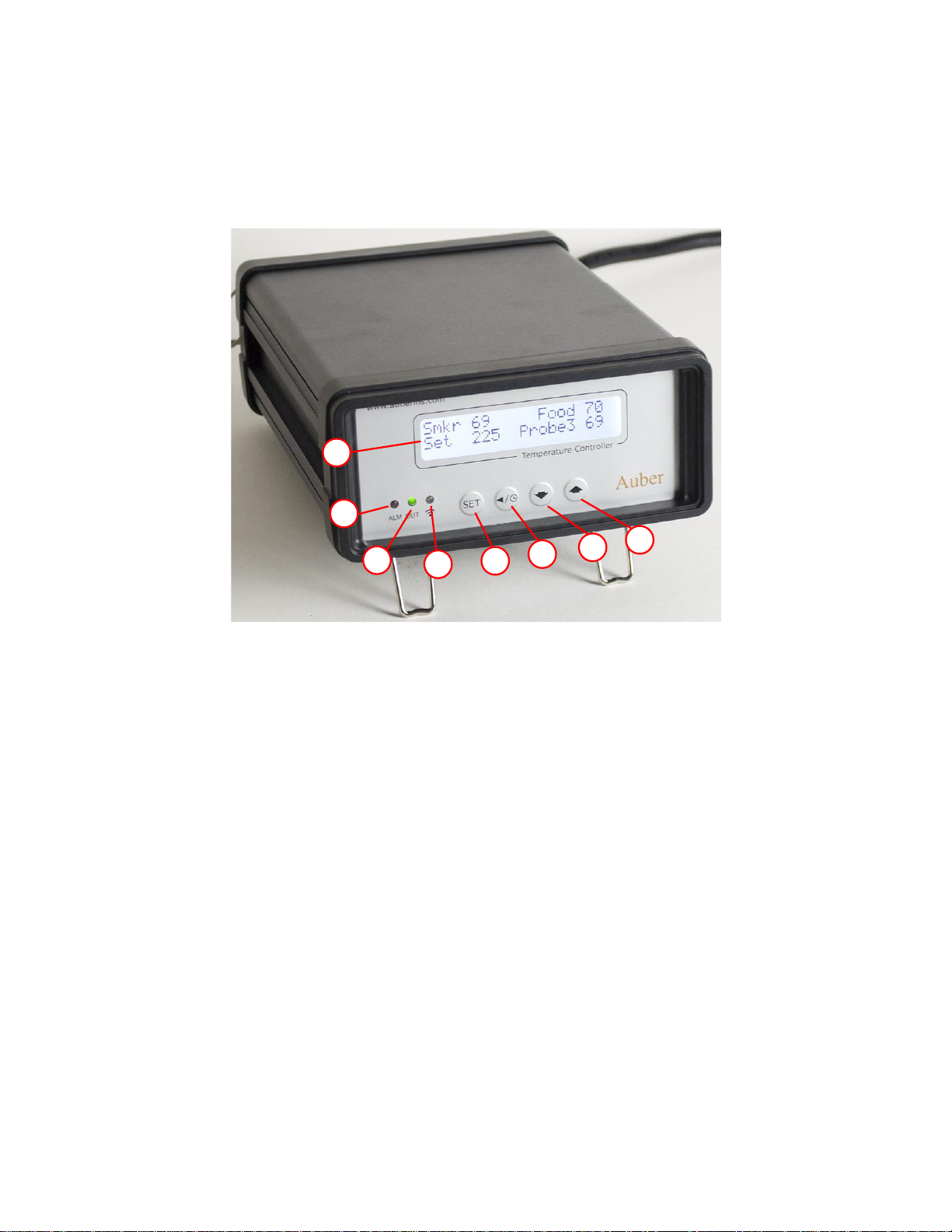
Figure 1. Front Panel.
1) LCD display window – During normal display mode, it will display temperature
readings from all probes and set temperature for cabinet. When high or low limit
alarm is triggered, this display will show alarm notification. In time checking mode,
it will display time/step information. In cooking profile or parameter setting modes,
it will display the step/parameter name and its value. For details, please check
section 3.
2) Alarm status/smoke generator indicator (Red)– This indicator has two
functions. When this indicator is blinking, temperature alarm is triggered. The LCD
display will flash the alarm notification at same time. When this indicator is solid
ON, the smoke generator control output is activated.
3) Output status indicator (Green)- This LED indicates the output status that
should be synchronized with heater. When this indicator is ON, the heater is
powered. When it is OFF, the heater’s power is off. When it is flashing, it means
the heater is on and off intermittently to reduce the power output. It is
synchronized with the power light on the cooking device.
4) Wi-Fi status indicator (Blue) – It indicates the Wi-Fi connection status of the
controller. Solid ON: the controller is connected to the internet. Fast flashing: Wi-Fi
Page 4
4/31
module is ready for configuration. Slow flashing: Wi-Fi module is initializing its
connection to the router. Off: no Wi-Fi connection.
5) SET Key – Press momentarily to enter the cooking profile settings. Press and hold
about 2 seconds to enter parameter settings. This key can also be used to confirm
the change of setting.
6) Time/Back Key – Pressing this key in normal operation mode will display time
checking mode. Pressing this key in the parameter setting mode will return back to
the upper level menu, or exit.
7) Down Key – Decrease value, scroll down the menu, or mute the buzzer.
8) Up Key – Increase value, scroll up the menu, or mute the buzzer.
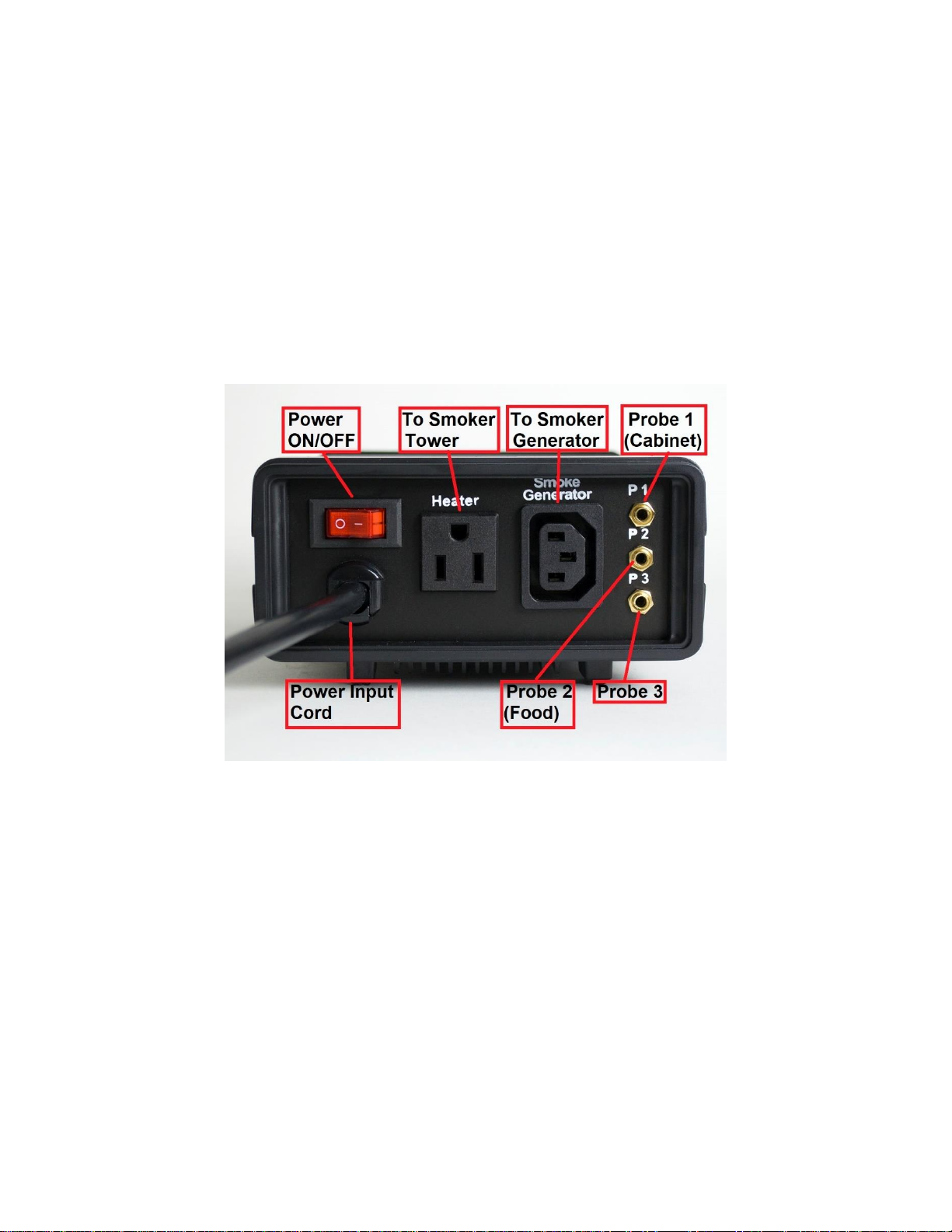
Figure 2. Back Panel.
Up to three temperature probes can be used with this controller, and they need to be
plugged in P1, P2 and P3 sockets on the right of the back panel. P1 socket is for cabinet
temperature probe (Probe 1); P2 socket is for food internal probe (Probe 2); P3 socket is
for 3
rd
temperature probe (Probe 3).
2. Connecting this controller to your smoker
Install the sensor.
(Note: If you ordered wall mount sensor instead of free hanging sensor, please see the
separate instruction for wall mount sensor installation.)
The controller is supplied with two probes by default. The one with the short tip is for
measuring the cabinet temperature (Probe 1). It needs to be plugged to the top sensor
jack at the back of the controller. The long probe with a bend at the end is for the meat
Page 5

5/31
internal temperature measurement (Probe 2). It needs to be plugged to the bottom
sensor jack at the back of the controller. The tips of the probes are dropped into the
damper hole. Place a piece of tape on the top of the smoker tower to hold them in
place. The tip of Probe 1 should be placed close to the food but high enough so that it
does not touch the food. (See Figure 3). The tip of Probe 2 is to be inserted into the
meat.
Figure 3. Sensor position. Left, the sensor should be placed close to the food but high enough so that it
does not touch the food. Right, hold the sensor in place by a piece of tape.
For the “Original” and Stainless Steel Bradley smoker, the Temperature Heat Control
Switch on the smoker tower should be set to the Hi position (most right).
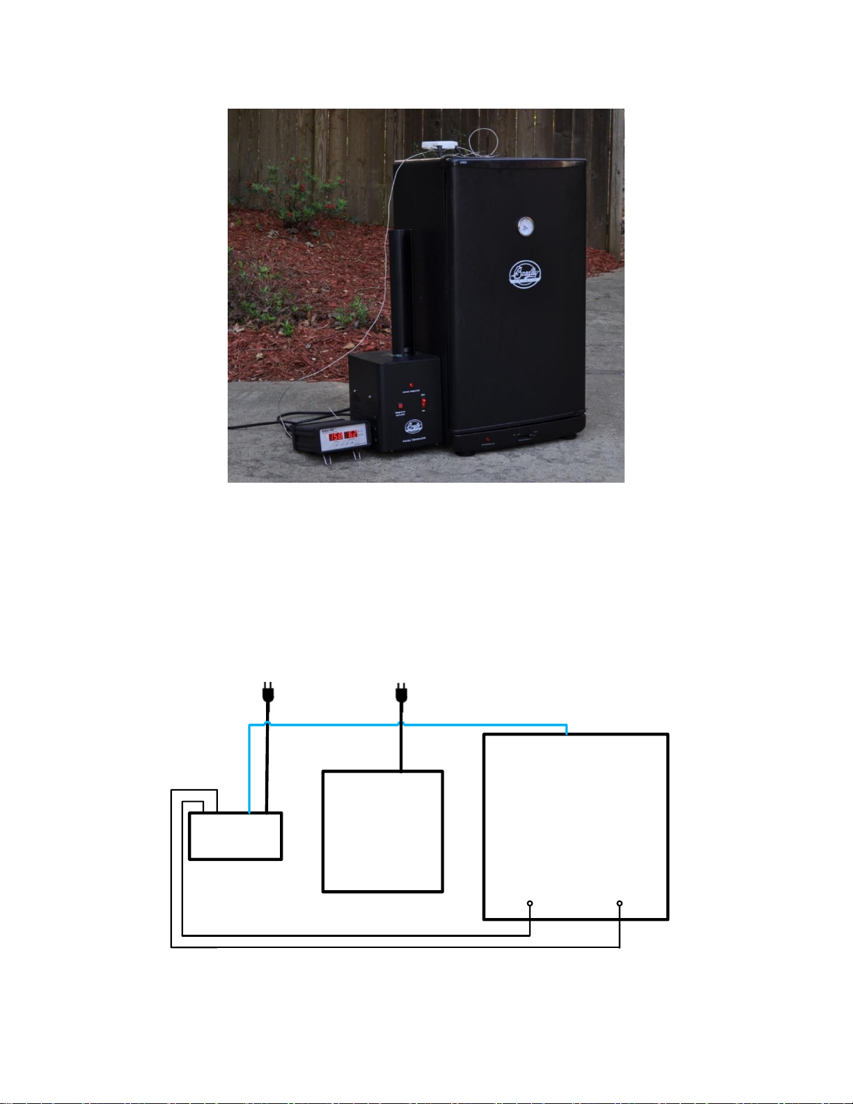
There are several ways to connect the controller and Bradley Smoker.
Smoke
Generator
Smoker
Tower
Cable B
Cable A
Figure 3.1 Power Cable wiring for Original Bradley Smoker
Cable A: Power cable for Smoker Tower, C14 plug
Cable B: Power cable for smoke generator, NEMA5-15P plug
Page 6
6/31
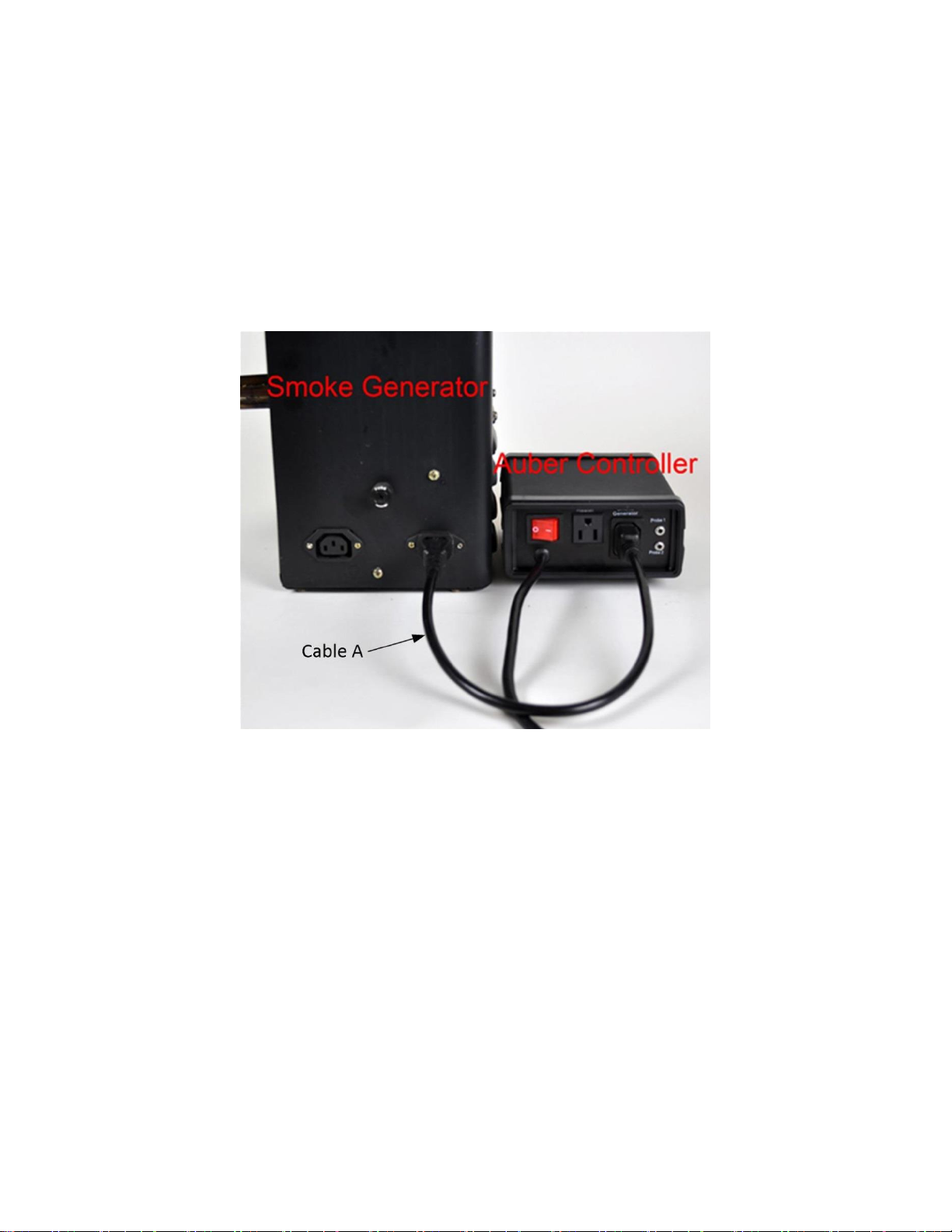
1) Connection for Bradley Original Smoker, with control of the smoker generator.
a) Connecting the controller to the power outlet, you should use the power cord that
came with the Bradley Smoker for connecting the smoker generator to the power outlet.
b) Connecting the controller to the smoker generator. You should use the power cord
that originally was used for connection between the smoker generator and smoker
tower.
Figure 4. Connection between the controller and Bradley Original Smoke generator.
Page 7
7/31
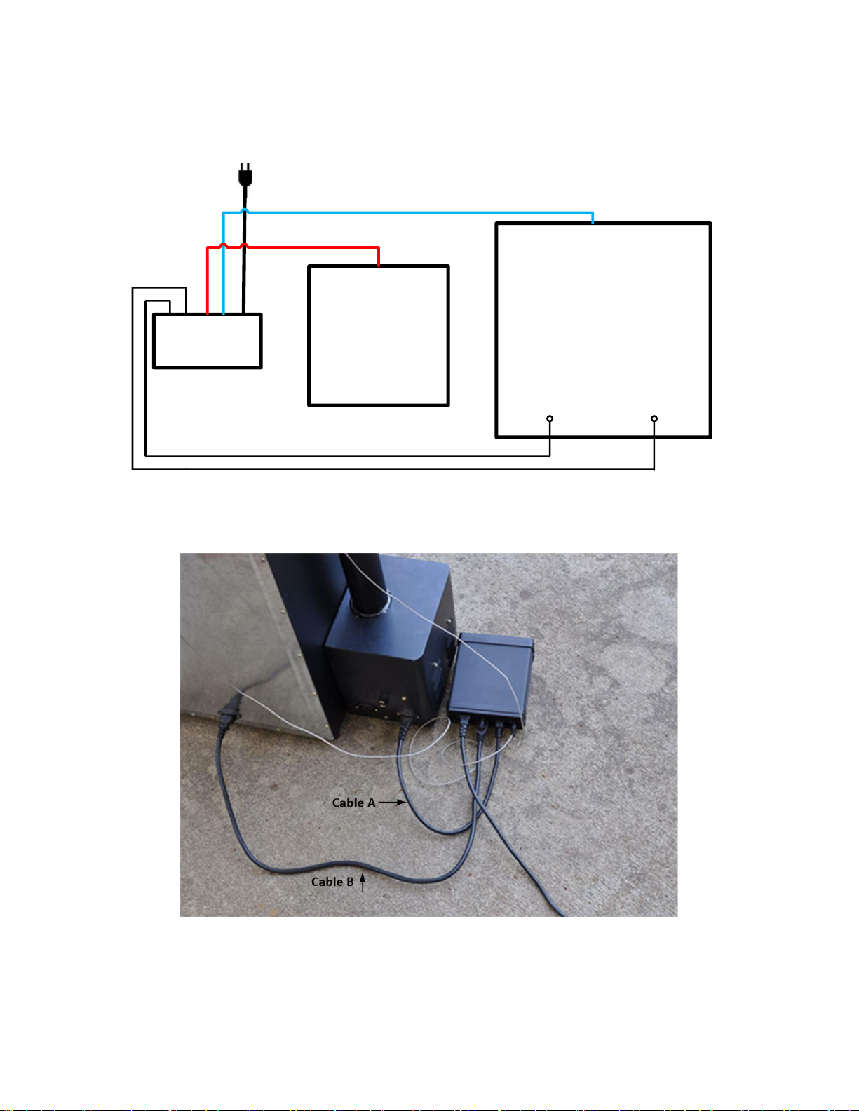
c) Connecting the controller output to the Bradley Smoker Tower with the power cord
that came with the Auber Controller
Auber
Controller
Smoke
Generator
Smoker Tower
Probe 1:
Cabinet Temp
Probe 2:
Internal Temp
Cable A
Cable B
To Power Outlet
Figure 5. Diagram
Figure 6. Back view
Page 8
8/31
Figure 7. Connection between the controller and smoker
2) Connection for Bradley Digital Smoker.
For the Bradley Digital Smoker, both controller and smoker generator should be
connected directly to the wall outlet. Connect the controller output with the smoker
tower.
Auber
Controller
Smoke
Generator
Smoker Tower
Probe 1:
Cabinet Temp
Probe 2:
Internal Temp
Cable C
Cable B
To Power Outlet
To Power Outlet
Figure 8. Connection for Bradley Digital Smoker
Cable C is extra 18 AWG power cord, same as Cable B
Page 9
9/31
3. Display modes
00000000000000000000
00000000000000000000
Smkr 137 Food 122
Set 250 Probe3 270
Normal Display
SET
Press
Momentarily
00000000000000000000
00000000000000000000
>Step 1 SmkrTemp 250
1- End i ng by Fd Temp
00000000000000000000
00000000000000000000
> 1 -Fd Temp 195
Step 2 SmkrTemp 200
|
Press
Momentarily
00000000000000000000
00000000000000000000
Step 1 Runt ime 0 : 02
Ends at 195
00000000000000000000
00000000000000000000
Tota l Runt ime 0 : 03
Power Out put 100%
o
00000000000000000000
00000000000000000000
> Cont ro l Sett i ng
System Con f i g
SET
Cooking Profile
SET
Press
Momentarily
SET
Press
Momentarily
SET
Press
Momentarily
SET
Time Checking
SET
Press
Momentarily
Parameter Settings
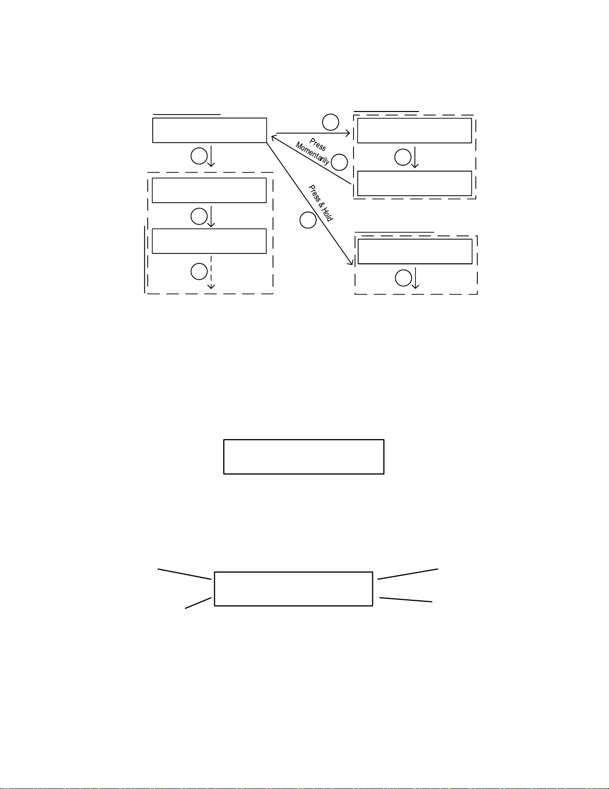
Figure 9. Switching between different display modes
Four display modes are available: 1) Normal display, 2) Time Checking, 3) Cooking
Profile and 4) Parameter setting.
When you turn on the controller, it will show the initializing display for several seconds. it
will display controller’s name and firmware version during this period. Then it will show
the normal mode display.
00000000000000000000
00000000000000000000
WSD-H -Wi F i
v1 . 00
Figure 10. Initializing display. Top line is for model number. Bottom line is for firmware version.
3.1 Normal display mode
00000000000000000000
00000000000000000000
Smkr 137 Food 122
Set 250 Probe3 270
Cabinet Temp. Food Probe Temp.
Cabinet
Set Temp.
Probe 3 Temp.
Figure 11-1. Information displayed in normal display mode (Default)
Page 10
10/31
00000000000000000000
00000000000000000000
Smkr 137 Food 122
Set 250 OUT 25
Cabinet Temp. Food Probe Temp.
Cabinet
Set Temp.
Power Output
Percentage
Figure 11-2. Information displayed in normal display mode
(when probe 3 is disabled in the setting, note 16 in section 7.2)
3.2 Time checking mode
To check current running status (status check mode), press Timer Key momentarily.
Press Time Key again to display more information, or return back to normal display
mode. Three display possibilities:
00000000000000000000
00000000000000000000
Tota l Runt ime 0 : 03
Power Out put 100%
Press
Momentarily
|
Press
Momentarily
00000000000000000000
00000000000000000000
Smkr 137 Food 122
Set 250 Probe3 270
|
Press
Momentarily
|
00000000000000000000
00000000000000000000
Step 1 Runt i me 0 : 02
Remai n i ng T ime 0 : 05
Figure 12. Time checking mode when current step is ended by time (multi-step mode).
Display #1 (if current step is ended by time): In normal mode, press timer key
momentarily to display the elapsed time for current step (top) and remaining time for
current step (bottom). Press timer key again to display the total running time after you
recently powered up the controller (top), and current power output percentage. Press
timer key again to return to normal display mode.
00000000000000000000
00000000000000000000
Step 1 Runt ime 0 : 02
Ends at 195
00000000000000000000
00000000000000000000
Tota l Runt ime 0 : 03
Power Out put 100%
o
Press
Momentarily
|
Press
Momentarily
00000000000000000000
00000000000000000000
Smkr 137 Food 122
Set 250 Probe3 270
|
Press
Momentarily
|
Figure 13. Time checking mode when current step is ended by food temperature (multi-step mode).
Display #2 (if current step is ended by food temperature): In normal mode, press timer
key momentarily to display the elapsed time for current step (top) and food probe
ending temperature (bottom). Press timer key again to display the total running time
Page 11

11/31
after you recently powered up the controller (top), and current power output percentage.
Press timer key again to return to normal display mode.
|
Press
Momentarily
00000000000000000000
00000000000000000000
Smkr 137 Food 122
Set 250 Probe3 270
00000000000000000000
00000000000000000000
Tota l Runt ime 0 : 03
Power Out put 100%
Figure 14. Time checking mode when single step mode.
Display #3 (if single step mode): Press timer key to display the total running time after
you recently powered up the controller (top), and current power output percentage.
Press timer key again to return to normal display mode.
3.3 Cooking profile programming mode
00000000000000000000
00000000000000000000
Smkr 137 Food 122
Set 250 Probe3 270
SET
Press
Momentarily
00000000000000000000
00000000000000000000
>Step 1 SmkrTemp 250
1- End i ng by Fd Temp
00000000000000000000
00000000000000000000
> 1 -Fd Temp 195
Step 2 SmkrTemp 200
SET
Press
Momentarily
SET
Press
Momentarily
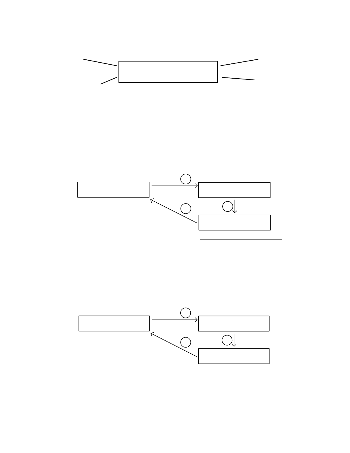
Figure 15. Access the menu of cooking profile mode using SET key.
Press SET key momentarily to enter cooking profile mode. For details, please check
section 4.1.
3.4 Parameter setting mode
00000000000000000000
00000000000000000000
Smkr 137 Food 122
Set 250 Probe3 270
00000000000000000000
00000000000000000000
> Cont ro l Sett i ng
System Con f i g
SET
Press & Hold
Figure 16. Access the menu of parameter setting mode using SET key.
Press and hold SET key for about 2s to enter parameter setting mode. For details, please
check section 5.
4. Operation
All cooking profile settings and control parameters can be accessed both from the device
and from AuberSmart app.
Page 12

12/31
4.1 Set the Cooking Profile
The controller’s cooking profile can be either set to multi-step mode (default) or singlestep mode. In the multi-step mode, up to 6 steps can be programmed. Each step has its
own set temperature for cabinet probe (Probe 1), and its step-ending criterion. A cooking
step can either end by timer or by food internal temperature (Probe 2). In the single-step
mode, the controller will try to maintain the cabinet temperature at the set value of Step 1
(“Step 1 SmkrTemp”) as long as the controller is on. To switch between single-step mode
and multi-step mode, please check section 4.1.3.
4.1.1 Multi-Step Mode
A total of 6 steps can be programmed on this controller. Each program step comprises a
target temperature of cabinet (shown as “SmkrTemp: XXX”) and an ending criterion
setting “X-Ending”, where “X” is the step number. For example, “1-Ending” means the
ending criterion of Step 1. The “ending criterion” is a new concept to people who never
used Auber’s controllers. It determines how a cooking step is considered finished. Two
options are available: time and food internal temperature (Probe 2). If you want Step X to
be ended after a pre-set time period, set “X-Ending” by “Time”; if you want Step X to be
ended when food internal temperature reaches a pre-set value, set “X-Ending” to “Fd
Temp”.
After you set “X-Ending” to “Time”, you will need to set “X-Time”. Here, “X-Time” is
defined as the time duration (in hh:mm format) of the current step. The timer will start
counting even if the cabinet temperature has not yet reached the target cabinet
temperature. So, please make sure that the step time is long enough. If the step time is
too short, the controller may continue to the next step no matter what the actually cabinet
temperature is. If you set “X-Ending” to “X-Fd Temp”, you will need to set “X-Fd Temp”
to the desired food temperature (Probe 2), but only one setting is relevant to the current
cooking step depending on the X-Ending setting (either X-Time or X-Fd Temp).
Timer or Target Food Temp.
1-T i me 10 : 00
1 -Fd Temp 195
Ending Criterion
1- End i ng by T ime
1- End i ng by Fd Temp
Step 1 SmkrTemp 250
Step Number and
Target Cabinet Temp.
Figure 17. For each cooking step, set the target cabinet temperature, ending criterion, and timer or target
food temperature.
If “X-Ending” of a certain step is set to “Fd Temp” while the food probe (Probe 2) is not
plugged in, this step will never end. Cabinet probe (Probe 1) should always be plugged
in, otherwise controller will stop sending power to the heater as protection. When all of
Page 13

13/31
the “X-Ending” are set to time, the controller can operate with only the cabinet probe
(Probe 1) plugged in.
Note: user can also use Aubersmart app to view and change both time and food
temperature of each step.
Cooking Profile Example
Table 1. example program
Step
Number
Cabinet Temp.
(SmkrTemp)
X-Ending
(Ending)
Time/
Fd Temp
1
120
Time
2:00 2 190
Fd Temp
160 3 130
Time
20:00 4 0
Time
0:0 5 0
Time
0:0 6 0
Time
0:0
The example program for the controller is listed in Table 1. This program will control the
temperature of the cabinet at 120°F for 2 hours. Then, change the temperature to
190°F. It will stay at 190°F until internal temperature of the meat reaches 160°F. Then,
the controller will drop the temperature to 130°F for 20 hours, waiting you to pick the
food. If you change set temperature in step 3 (Step 3 SmkrTemp) to 0 and time for step
3 to 0, when food internal temperature reaches 160°F, the controller will shut off the
heater and stop the program. it will give beeping sound until the buzzer is muted or the
power input has been reset.
A flow chart of how to enter the cooking profile is shown in Figure 18. To start program
the cooking profile, press SET key shortly to enter the Cooking Profile Programming mode.
The top line in the display shows the step number “Step: 1” and the current target of
cabinet temperature “SmkrTemp 250”. To enter or edit the profile:
1) Use ▲ or ▼ key to move the cursor “>” to the parameter you want to edit.
2) Press SET key, the value to be edited should start blinking.
3) Use ▲ or ▼ arrow key to edit the value.
4) Then press SET key again to save the change. That parameter will stop blinking.
5) Use ▲ or ▼ key to go another parameter, repeat the previous operations till you
have finished entering all the cooking steps.
Note: New setting will NOT be saved if SET key is not pressed. After programming the
necessary steps for cooking, you can finish programming by pressing the Time/Back key
Page 14

14/31
to exit the menu. Or, you can use ▲ or ▼ key to go to “Back”, and press SET key to
exit. The display can also return to the normal display mode if no key is pressed in about
15 seconds.
00000000000000000000
00000000000000000000
>Step 1 SmkrTemp 250
1- End i ng by Fd Temp
00000000000000000000
00000000000000000000
> 1- End i ng by Fd Temp
1 -Fd Temp 195
00000000000000000000
00000000000000000000
> Back
Step 1 SmkrTemp 250
00000000000000000000
00000000000000000000
> 1-T i me 10 : 00
Step 2 SmkrTemp 250
00000000000000000000
00000000000000000000
Smkr 137 Food 122
Set 250 Probe3 270
Step 1 SmkrTemp 250 Step 1 SmkrTemp 120
1- End i ng by Fd Temp
1- End i ng by Time
1-T i me 10 : 00
1-T i me 2 : 00
00000000000000000000
00000000000000000000
>Step 2 SmkrTemp 250
2- End i ng by Fd Temp
00000000000000000000
00000000000000000000
>2-End i ng by Fd Temp
2-Fd Temp 195
00000000000000000000
00000000000000000000
>2-Fd Temp 195
Step 3 SmkrTemp 250
Step 2 SmkrTemp 250
Step 2 SmkrTemp 190
2- End i ng by Fd Temp
2- End i ng by Fd Temp
2-Fd Temp 195 2-Fd Temp 160
SET
SET
SET
SET
SET
SET
SET
/
/
/
/
/
/
SET
SET
SET
SET
SET
SET
Figure 18. How to enter a cooking profile.
The example program in table 1 is used in this flow chart as a demo.
4.1.2 Single-Step Mode
In single-step mode, you can only access and change the target cabinet temperature of
Step 1 from the device. The controller will try to maintain the smoker temperature at the
set temperature (Smkr Temp) of Step 1 continuously as long as the controller is powered
on. If this controller is powered off and turned back on again, it will resume operating in
this mode. You can still view and change settings in other steps in Cooking Profile on the
Aubersmart app, but they don’t apply to this mode.
To change the set temperature in single-step mode, press SET key once, it will show
Page 15

15/31
“Step: 1” and the current target cabinet temperature in the top line. A curser “>” will be
shown on the left indicating which line will be selected. Press SET key once, the current
set temperature should start blinking. Use ▲ and ▼ keys to change the set
temperature. When finished, press the SET again to confirm the change. That number
will stop blinking. Press the Timer/Back key to exit the menu. Or use ▲ or ▼ key to
scroll to “Back” and then press SET key to exit. The display will return to the normal
display mode if no key is pressed in 15 seconds.
00000000000000000000
00000000000000000000
>Step 1 SmkrTemp 250
Back
00000000000000000000
00000000000000000000
Smkr 137 Food 122
Set 250 Probe3 270
00000000000000000000
00000000000000000000
>Step 1 SmkrTemp 250
Back
00000000000000000000
00000000000000000000
Step 1 SmkrTemp 250
> Back
SET
Press
SET
Press
Use or keys to adjust
set pit temp. Press SET key
to confirm.
Press
SET
Figure 19. How to change the set temperature in single-step mode.
4.1.3 Program Status & Control (for firmware version 1.7.4 or newer)
User can check or change current program running status by this parameter. It can be
used to stop/start the program, or jump to a different step. This parameter is under the
Cooking Profile menu as stated in section 4.1. Parameter name showing on the
controller’s display is Prog Status. Available options for this parameter are: Stop, Start,
Step 1 ~ 6, Back.
When pressing SET button momentarily to enter Cooking Profile menu, it will display
Prog Status on the left top, and current step number or stopped status on the right top.
Press SET button again, then user can change its options to start/stop the program or
jump steps. Press SET button again to confirm the change. See option definition and
flow chart below.
Option definition:
Stop: Stop the current cooking program.
Start: Start the cooking program from Step 1.
Step 1 ~ 6: Jump to specific step. For example, if user selects Step 3, controller will skip
Step 1 & 2, and run rest steps starting at Step 3. If the controller program is stopped,
selecting those options will also exit stopped mode. Step 1 ~ 6 options are available for
multi-step mode only. For single-step mode, only Step 1 is available.
Back: Go back to upper level. Parameter is unchanged.
Page 16

16/31
00000000000000000000
00000000000000000000
>Step 1 SmkrTemp 250
1- End i ng by Fd Temp
00000000000000000000
00000000000000000000
> Back
Step 1 SmkrTemp 250
00000000000000000000
00000000000000000000
Smkr 137 Food 122
Set 250 Probe3 670
Step 1 SmkrTemp 250 Step 1 SmkrTemp 120
SET
SET
/
SET
00000000000000000000
00000000000000000000
>Prog S tatus Stop
Step 1 SmkrTemp 250
Prog S tatus Stop
Prog S tatus Start
SET
/
SET
Figure 18A. Flow chart of how to use Program Status & Control function.
4.1.4 Switch between single-step mode and multi-step mode
To switch between single-step mode and multi-step mode, go to Parameter Setting mode
by holding the SET key, and then go to “System Config” menu, find parameter “Program
Mode”, then change it to “ON” (for multi-step mode) or “OFF” (for single-step mode). By
default, the controller is set to multi-step mode “ON”. Please see the flow chart in Figure
20 for how to access this parameter from the controller.
00000000000000000000
00000000000000000000
> System Con f i g
Back
00000000000000000000
00000000000000000000
>Program Mode ON
Output Hi L im i t 100
Program Mode ON
Program Mode OFF
SET
SET
/
SET
00000000000000000000
00000000000000000000
>Back
Program Mode ON
SET
Multi-step Mode Single-step Mode
00000000000000000000
00000000000000000000
Smkr 137 Food 122
Set 250 Probe3 270
SET
Press & Hold
Figure 20. How to switch between programmable mode and single-step mode
5. Controller parameter setup.
To access the parameters, press and hold SET key for about 2 seconds. Parameters are
divided into two groups: “Control Config” and “System Config”.
Page 17

17/31
7.1 Control Configurations
Parameters related control configurations during the smoking process are listed under
“Control Config” menu. Error! Reference source not found. shows the list of these
parameters, their range and initial set value when left the factory. The flow chart in
Figure 21 shows the operations of accessing and adjusting the parameters in “Control
Config”.
Table 2. Parameters in Control Config menu.
Name
Description
Range
Initial
Note
Smkr Hi Alarm
Cabinet Probe High Alarm
(Probe 1)
0 - 750
350
1
Smkr Lo Alarm
Cabinet Probe Low Alarm
(Probe 1)
0 - 750
50
2
Food Hi Alarm
Food Probe High Alarm
(Probe 2)
0 - 650
350
3
Probe3 Hi Alarm
Probe 3 High Alarm
0 - 650
300
4
Relay Action
Smoke Generator
Relay Setting
0 - 63
0
5
P (Proportional)
Proportional Constant
1 - 999
7
6
I (Integral)
Integral Time
0 - 9999
600
7
D (Derivative)
Derivative Time
0 - 999
150
8
T (Cycle Time)
Control Cycle Time
2 - 200
2
9
Auto-tune
Auto-tune
ON, OFF
OFF
10
Save Recipe
Save Recipe Settings
Back, B1, B2, C1, C2, F1, F2
Back
11
Recall Recipe
Recall Recipe Settings
Back, B1, B2, C1, C2, F1, F2
Back
11
Back
Back to Upper Level Menu
Page 18

18/31
00000000000000000000
00000000000000000000
> Cont ro l Sett i ng
System Con f i g
00000000000000000000
00000000000000000000
>Smkr Hi A l arm 350
Smkr Lo A l arm 50
00000000000000000000
00000000000000000000
> Smkr Hi A l arm 50
Food Hi A l arm 350
Smkr Hi A l arm 350
Smkr Hi A l arm 250
Smkr Hi A l arm 50
Smkr Hi A l arm 50
SET
SET
SET
/
/
SET
SET
00000000000000000000
00000000000000000000
>Back
Smkr Hi A l arm 350
SET
Figure 21. Access the parameters in Control Config menu.
Note 1. Smkr Hi Alarm: This is the high temperature alarm for cabinet temperature
(Probe 1). When cabinet probe reading is higher than Smkr Hi Alarm, the buzzer on the
controller will go off and the LCD display will flash between the normal display and the
alarm display showing in Figure 22. The alarm has 1 degree hysteresis. The user can
mute the buzzer by pressing either the Up key or the Down key. Temperature must move
out of the hysteresis zone to activate the alarm again. For example, if Smkr Hi Alarm is
set to 290°F, the buzzer will go off when Probe 1 reads higher than 291°F, and the buzzer
will stop when Probe 1 reads lower than 289°F. To disable Smkr Hi Alarm alarm, you
can set it to a large number, such as 750°F.
00000000000000000000
00000000000000000000
Smkr H i gh A l arm
Press v to Cance l
Figure 22. The LCD display when Smkr Hi Alarm is triggered.
Note 2. Smkr Lo Alarm: This is the low temperature alarm for cabinet temperature
probe (Probe 1). When cabinet probe reading is lower than Smkr Lo Alarm, the
buzzer on the controller will go off and the LCD display will flash between the normal
display and the alarm display showing in Figure 23. The alarm has 1 degree hysteresis.
The user can mute the buzzer by pressing either the Up key or the Down key.
Temperature must move out of the hysteresis zone to activate the alarm again. For
example, if Smkr Lo Alarm is set to 180°F. The buzzer will go off when cabinet
temperature drops to 179°F; it will stop when temperature rise above 181°F. The Smkr
Lo Alarm is suppressed when the controller is just powered up. It will be activated
when the cabinet temperature has reached the target cabinet temperature. To disable
Page 19

19/31
the Smkr Lo Alarm, you can set it to a small number, such as 0°F (default).
00000000000000000000
00000000000000000000
Smkr Low A l arm
Press v to Cance l
Figure 23. The LCD display when Smkr Lo Alarm is triggered.
Note 3. Food Hi Alarm: This is the high temperature alarm for the food internal probe
(Probe 2). When food probe reading is higher than Food Hi Alarm, the buzzer on the
controller will go off and the LCD display will flash between the normal display and the
alarm display showing in Figure 24. The alarm has 1 degree hysteresis. The user can
mute the buzzer by pressing either the Up key or the Down key. For example, if Food Hi
Alarm is set to 130°F, the buzzer will go off when Probe 2 reads 131°F, and the buzzer
will stop when Probe 2 reads 129°F or lower. To disable Food Hi Alarm, you can set it
to a large number, such as 650°F.
When smoking multiple pieces of meat of different sizes or thickness, you can put the
probe in the thinnest piece first. Set the Food Hi Alarm to the temperature when meat
is ready. It will let you know when it is done. Then, you can move the probe to the second
thinnest pieces and so on. To use this feature, you can set the ending criterion to time. If
you prefer to set the ending criterion to food temperature, then the Food Temp should be
set to higher than Food Hi Alarm.
00000000000000000000
00000000000000000000
Food H i gh A l arm
Press v to Cance l
Figure 24. The LCD display when Food Hi Alarm is triggered.
Note 4. Probe3 Hi Alarm: This is the high temperature alarm for probe 3. When food
probe 3 reading is higher than Probe3 Hi Alarm, the buzzer on the controller will go off
and the LCD display will flash between the normal display and the alarm display showing
in Figure 25. The alarm has 1 degree hysteresis. The user can mute the buzzer by
pressing either the Up key or the Down key. For example, if Probe3 Hi Alarm is set to
130°F, the buzzer will go off when Probe 3 reads 131°F, and the buzzer will stop when
Probe 3 reads 129°F or lower. To disable Probe3 Hi Alarm, you can set it to a large
number, such as 650°F.
00000000000000000000
00000000000000000000
Probe3 H i gh A l arm
Press v to Cance l
Figure 25. The LCD display when Probe3 Hi Alarm is triggered.
Page 20

20/31
Note 5. Relay Action: This is smoke generator relay setting. This parameter
determines which steps to turn on smoke generator output. Its configuration range is
from 0 to 63. It is determined by the following formula:
Relay Action = A * 1 + B * 2 + C * 4 + D * 8 + E * 16 + F * 32;
If A = 0, smoke generator output is OFF at Step 1.
If A = 1, smoke generator output is ON at Step 1.
If B = 0, smoke generator output is OFF at Step 2
If B = 1, smoke generator output is ON at Step 2.
If C = 0, smoke generator output is OFF at Step 3.
If C = 1, smoke generator output is ON at Step 3.
If D = 0, smoke generator output is OFF at Step 4.
If D = 1, smoke generator output is ON at Step 4.
If E = 0, smoke generator output is OFF at Step 5.
If E = 1, smoke generator output is ON at Step 5.
If F = 0, smoke generator output is OFF at Step 6.
If F = 1, smoke generator output is ON at Step 6.
Example:
To turn on smoke generator output on step 2 and step 3 only, this parameter needs to be
set to 6. (0 * 1 + 1 * 2 + 1 * 4 + 0 * 8 + 0 * 16 + 0 * 32 = 6.)
To turn on smoke generator output on step 1 only, set this parameter to 1.
Note 6. P: Proportional Constant. The unit is 1 degree. This parameter controls the output
of the controller based on the difference between the measured and set temperature.
Larger the P number means the weaker the action (lower gain). If P = 7, the proportional
band is 7 degree. When the sensor temperature is 7 degrees below the proportional band
(10 degrees below the setting), the controller will have 100% output. When the
temperature is 5 degree below the set point, the output is 71%. When the temperature is
equal to the setting, the controller will have 0% output (assuming integral and derivative
functions are turned off). This constant also affects both integral and derivative action.
Smaller P values will make the both integral and derivative action stronger. Please note
the value of the P is temperature unit sensitive. If you found an optimized P value when
operating the controller in Fahrenheit, to use in Celsius, that optimized P value needs to
be divided by 1.8. This controller will automatically convert the current P value if you
change the temperature display unit.
Note 7. I: Integral Time. The unit is in seconds. This parameter controls the output of
controller based on the difference between the measured and set temperature integrated
with time. For example, if I = 1000, it means if the temperature difference between the
Page 21

21/31
cabinet temperature and set temperature stays constant, the output will be doubled after
1000 seconds. Integral action is used to eliminate temperature offset. Larger number
means slower action. E.g. assuming the difference between the measured and set
temperature is 2 degrees and remain unchanged, the output will increase continuously
with time until it reaches 100%. When temperature fluctuate regularly (system oscillating),
increase the integral time. Decrease it if the controller is taking too long to eliminate the
temperature offset. When I = 0, the system becomes a PD controller. For very slow
response system such as slow cooker and large commercial rice cooker, set I = 0 will
significantly reduce the temperature overshoot.
Note 8. d: Derivative Time. The unit is in seconds. Derivative action contributes the output
power based on the rate of temperature change. Derivative action can be used to
minimize the temperature overshoot by responding its rate of change. The larger the
number is, the stronger the action will be. For example, when the door of oven is opened,
the temperature will drop at very high rate. The derivative action changes the controller
output based on the rate of change rather than the net amount of change. This will allow
the controller to act sooner. It will turn the heater to full power before the temperature
drops too much.
Note 9. T: Control Cycle Time. The unit is second. This unit determines how long for the
controller to calculate each action. e.g. If T is set to 10 seconds, when controller decide
the output should be 10%, it will turn on the heater 1 second for every 10 seconds. This
parameter should be set at 2 second for heating with an electric heater.
Note 10. Auto-tune: This parameter can be used to initial the auto-tune process. Set
Auto-tune to ON then press SET key to confirm. Once exit (in normal display mode), the
display will flash alternately between normal display and auto-tune notification (Autotuning Please wait…), which indicates auto-tuning is in progress. When the display stops
flashing, the auto-tuning process is finished. Now, the newly calculated PID parameters
are set and are used for the system. The new parameters will store in the memory even
the power is off. To cancel the current auto-tuning process, please set this parameter to
OFF. For more information about auto-tune, please see section 10.
Note 11. Save & Recall Recipes: This controller can save up to 6 pieces of smoking
recipe (programs). Each recipe file can have up to 6 steps (C-1 to C-6). For convenience,
we have pre-named these 6 pieces of recipe files as B1 (beef), B2, C1 (chicken), C2, F1
(fish), F2. These recipe files are all the same except their names, so you can store your
special recipe to any of them. These recipes can be stored in the memory of the controller
even when it is powered off. You can overwrite the exist recipe with a new one.
Page 22

22/31
Note 11.1 Save a recipe
After a recipe has been entered, the user can save this current program as a recipe for
future use.
Go to Parameter Setting mode by holding the SET key, and then go to “Control Setting”
menu, find parameter “Save Recipe”, press SET key again so you can change its value.
If you press ▲ or ▼ key repeatedly, you will see “Back”, “B1”, “B2”, “C1”, “C2”, “F1”,
“F2” one by one. Locate the recipe you want to save to, then press SET key to confirm.
Figure 26 shows the flow chart of how to save a recipe.
00000000000000000000
00000000000000000000
> Cont ro l Sett i ng
System Con f i g
00000000000000000000
00000000000000000000
>Smkr Hi A l arm 350
Smkr Lo A l arm 50
00000000000000000000
00000000000000000000
>Save Rec i pe Back
Reca l l Rec i pe Back
Save Rec i pe Back
Save Rec i pe B1
SET
SET
/
/
SET
00000000000000000000
00000000000000000000
>Back
Smkr Hi A l arm 350
SET
Figure 26. Flow chart of saving a recipe.
Note 11.2 Recall a recipe
You can recall your previous saved recipe to your current program. Please note your
current program will be overwritten. Please write your current program down somewhere
if it is important to you.
Go to Parameter Setting mode by holding the SET key, and then go to “Control Setting”
menu, find parameter “Save Recipe”, press SET key again so you can change its value.
If you press ▲ or ▼ key repeatedly, you will see “Back”, “B1”, “B2”, “C1”, “C2”, “F1”,
“F2” one by one. Locate the recipe you want to save to, then press SET key to confirm.
7.2 System Configurations
Parameters related device configurations which are not often used during the smoking
process are listed under “System Config” menu. Details of each parameters are listed in
Table 3. The flow chart in Figure 27 shows the operations of accessing and adjusting the
parameters in “System Config”.
Page 23

23/31
Table 3. Parameters in System Config menu.
Name
Description
Range
Initial
Note
Program Mode
Multi-Step Program
ON, OFF
ON
12
Output Hi Limit
Output High Limit %
0 - 100
100
13
Temp Unit
Temp Unit (°C or °F)
C, F
F
14
Smkr Probe Offset
Cabinet Probe (Probe 1) Offset
-9 - 99
0
15
Fd Probe Offset
Food Internal Probe (Probe 2) Offset
-9 - 99
0
15
Probe3 Offset
Probe 3 Offset
-9 - 99
0
15
Probe3 Enabled
Probe 3 Readout Option
Yes, No
Yes
16
Step End Alarm
Step Ending Alarm
ON, OFF
ON
17
Backlight Level
LCD Backlight Level
0 - 10
10
18
Dwell Time
Data Logging Sampling Interval (App)
1min - 5min
1min
19
nFlt
Power Line Digital Filter
Auto, A, B
Auto
22
Password
Device Access Password (App)
100 - 999
777
20
Factory Reset
Factory Reset
Yes, No
No
21
Back
Back to Upper Level Menu
00000000000000000000
00000000000000000000
> System Con f i g
Back
00000000000000000000
00000000000000000000
>Program Mode ON
Output Hi L im i t 100
00000000000000000000
00000000000000000000
Program Mode ON
Program Mode OFF
Output H i L im i t 100
Output H i L im i t 95
SET
SET
SET
/
/
SET
SET
00000000000000000000
00000000000000000000
>Back
Program Mode ON
SET
>Output H i L im i t 100
Temp Unit F
Figure 27. Access the parameters in System Config menu.
Note 12. Program Mode: Multi-step program switch. By default, this controller is set to
multi-step mode, and this parameter is set to “ON”. If you want to change it to single-step
mode, please change this parameter to “OFF”. For details regarding multi-step mode,
please check section 4.1.3
Note 13. Output Hi Limit: It is expressed as a percentage value. This function will allow
you to control the maximum output power delivered by the heater. For example, if you
set Output Hi Limit = 50 and your heater is 1000 watts, the output will use 50% of the
1000 watts as the full output. It thinks the 1000W heater as a 500W heater. When the
Page 24

24/31
PID algorithm determines 50% output value, the actual power output will be 250 watts.
This function can be used in two situations.
1) When you have a very powerful heater and using a very small pot of water to cook at
very low temperature, for example, a 1400 watts heater with a one litter (1 qt) pot of
water at 130°F. The heater is too powerful for the small water volume. The moment it is
on, it releases too much energy to cause the temperature to overshoot. Although it is
still possible to stabilize the temperature with proper PID parameters, it is much easier
to control if you limit the maximum output to 25%. Ideally, an optimized temperature
control system should consume about 25% of the heater power at set temperature
(steady state), for example, if you found out that only 50 watts of energy is needed to
maintain the temperature at 60°C (141°F), ideally you should use only 200 watts heater
for this job. Too much power will make the system over react too quickly. Too little power
will make the system too slow in response. By using the Out function, you can make the
1400 watts heater to act as a 200 Watts heater for stable temperature control.
2) When the cooker consumes more power than controller can handle, for example, if
you have a 12A, 120V AC heater and your cooker contains more than 38 Liter (10
Gallon) of water. It might take more than 90 minutes of full power heating for controller
to heat up the pot. Long time of full power operation might cause the controller to
overheat. You can set the output to 80%. It will prevent the controller from over heat by
staying a full power too long. For details, please see Appendix 1.
Note 14. Temp Unit: You can set the display either Celsius (°C) or Fahrenheit (°F).
Note 15. Probe calibration offsets: These parameters are used to make the input offset
to compensate the error produced by sensor. e.g. if the temperature displays of cabinet
probe (Probe 1) is 2°C in ice water mixture, set Smkr Probe Offset = -2 will make the
display to shown 0 degree. Three offset parameters are available for three probes. Smkr
Probe Offset is for cabinet probe (Probe 1); Fd Probe Offset is for food internal probe
(Probe 2); Probe3 Offset is for Probe 3.
Note 16. Probe3 Enabled: Probe 3 Readout Option. When this option is set to “Yes”,
right bottom parameter in normal display mode will show the temperature of probe 3.
When this option is set to “No”, that location will show the current power output percentage
instead. Please check section 3.1 for details.
Note 17. Step End Alarm: Step ending alarm setting. When Step End Alarm is set to
“ON”, the buzzer will beep 4 times when each step is finished. It is useful to notify the
user the cooking step is finished. User can turn it off if no buzzer sound is wanted at the
finish of each step.
Page 25

25/31
Note 18. Backlight Level: LCD backlight level setting. The higher the value, the brighter
the LCD display. 0 is lowest brightness. 10 is highest brightness.
Note 19. Dwell Time: Data Logging Sampling Interval. This parameter controls the
temperature sampling interval, which will be used for data export function and plot display
on Aubersmart app. The controller will store 5 data traces in total: SV, Probe 1 reading
(cabinet), Probe 2 reading (food probe), Probe 3 reading and the output power
percentage. Each trace can store up to 300 data points. The temperature plot of the
Aubersmart App has two scales. One can display the latest 300 data points and other can
display the latest 120 data points. The default setting of Dwell time is 1 minute per sample.
At this setting, 300 minutes (or 5 hours) of data points can be stored. User can display
the plot in either 5 hours or 2 hours. The dwell time can be set in the range of 1 minute to
5 minutes. Table 4 shows the available plot scales for the corresponding dwell time.
Table 4. Available options for Dwell Time.
Dwell Time Option
(Interval time per sample)
Maximum Logging Time
Plot Display Option
1-minute
5-hour
2-hour/5-hour
2-minute
10-hour
4-hour/10-hour
3-minute
15-hour
6-hour/15-hour
4-minute
20-hour
8-hour/20-hour
5-minute
25-hour
10-hour/25-hour
Note: Once the dwell time is set, the app can only display the temperature plot in the two
scales listed in the table. If you want to change the dwell time in the middle of cooking,
you will lose all the data logged before the change. If you want keep the data, you should
export the data before change this setting.
Note 20. Password: Device access password. This parameter is used to lock the access
to parameter settings on Aubersmart app. Default password is 777.
Note 21. Factory Reset: Factory reset. This function will restore all the parameters
(including all the stored recipe settings in the memory) back to the factory default values.
This setting will not reset the WiFi configuration. To reset the WiFi setting on the controller,
please press and hold SET key and TIME key for 5s, until the blue WiFi indicator starts
to blink.
Note 22. nFlt: Power line digital filter. This filter is for rejecting the power line interference.
There are three settings: “Auto” for auto-detect mode (default), “A” for 50 Hertz
interferences and “B” for 60 Hertz interferences. If you encounter fast fluctuating
temperature reading issue, you can change this setting to “A” or “B” manually, based on
Page 26

26/31
your local power line frequency.
8. Important consideration for better control results.
The following is a list of things that could affect the result of temperature control.
a) The smoker and controller location. The smoker should not be placed directly in the
sun. Direct sun light can heat the smoker to above 140 °F in the summer time, making
controlling the temperature at 140 °F impossible. This is especially the problem for the
black color smoker. The controller should be placed away from direct sun light also..
Users should also avoid exposing the controller to water and rain, which could damage
the controller.
b) Low temperature control. The control result for temperatures below 125 °F will not be
as accurate as for higher temperatures when the smoker generator is on. This is
because there are two heaters in the smoker tower. One is the smoker heater controlled
by the PID controller. The other is the heater from the generator that is not controlled.
Our test shows that the heater in the generator itself can raise the temperature of the
smoker tower by 60 °F (2 hours, in the shade with damper open). That means when the
ambient temperature is at 70 °F, the smoker can be heat up to 130 °F in 2 hours by the
heater of the generator (without using the heater in the smoker).
c) Damper position. Keeping the damper open will result in better temperature stability
because more heat loss is created. This is important when the temperature is set below
140 °F. When the damper is closed, the temperature will take longer time to drop if it is
overshot during initial heat up. At higher temperature, closing the damper will not affect
the performance much because the heat loss from the wall of the tower is increased.
Close the damper at high temperature will keep the moisture of the food.
d) Temperature uniformity of the smoker tower. Our test shows that when the all the
shelves were empty, the temperature inside the smoker tower is fairly uniform except
the back half of the lowest shelf that is close to the heater. User should avoid placing
the sensor too close to the heater because it does not represent the temperature of the
rest area. When the shelves are filled, temperature variation might depend on how the
foods were placed. The bottom shelf can become hotter if more food is placed in it to
block the hot air from going up.
9. Tuning the controller
This controller is shipped with the system parameters set for the Bradley Smoker. The
user should not change these parameters if you want to control a Bradley Smoker.
Otherwise, if you feel that performance is not ideal, you can try to manually tune the
Page 27

27/31
system or run the auto-tune again. For detailed information on how to tune the
controller, please read the section 10 for tuning the controller.
10. Auto-Tune
This section can be ignored if you are using the controller to control the Bradley Smoker
because the controller already set for it.
The controller's most powerful feature is its ability to regulate virtually any cooker with
stable temperature control. For stable temperature control the controller requires two
things; (1) the controller must be set to the correct power level (see next section) and,
(2) that it must be tuned to the cooker being used. Tuning is the process that matches
the control characteristics of the controller to the heating characteristics of the cooker.
The controller is said to be tuned to the cooker when its memory is programmed with
values telling it how fast the cooker warms up, cools off, and how efficiently it transfers
heat. For example, consider the difference between a heat lamp and a hot plate. When
electricity is applied to a heat lamp it begins to heat instantaneously, and when it's
turned off it stops heating instantaneously. In contrast, a hot plate may take several
minutes to begin heating when electricity is applied and even longer to start cooling
when electricity is turned off. But, to do this it must be programmed with the time
constants. Describing how fast the heater heats when electricity is turned on and how
fast it begins to cool when it's turned off. These time constants are called the tuning
parameters.
Every type of cooker has its own unique set of tuning parameters. For the controller to
heat with stability, it must have programmed with the tuning parameters for the cooker
currently being used.
When Should the Controller be Tuned?
If the PID parameters we provided are not working for your liking, you can use the autotuning function to let the controller to determine the PID parameters automatically. Autotuning function (it’s often known as self-tuning) can automatically optimize the PID
parameters for your chosen cooking system. The auto-tuning function will heat up your
cooker then let it cool down. It will repeat this heat/cool cycle several times. Based on
the response time of the whole cooking system, the controller will calculate and set the
PID parameters for your cooker.
Page 28

28/31
Figure 28. Auto-tune
Before using the auto-tune function, you must set the cooking equipment up in the exact
configuration it will be used. For example, to tune a rice cooker, place the sensor in the
room temperature pot filled with water and plug the cooker into the controller. If the
cooker has its own thermostat or power control, turn both as high as they’ll go. Set the
controller to the appropriate power level (see next Section). Turn the controller and
cooker on, and then enter the desired set point temperature closed to your normal
cooking temperature.
To activate auto-tuning, enter Control Config menu. Go to parameter "Auto-tune", and
set it to ON then exit the menu. the display will flash alternately between normal display
and auto-tune notification (Auto-tuning Please wait…), which indicates auto-tuning is in
progress. When the display stops flashing, the auto-tuning is finished. Now, the newly
calculated PID parameters are set and are used for the system. The new parameters
will store in the memory even the power is off.
You should always write down your old PID parameters, before letting the controller to
perform auto-tuning. This way if something goes wrong, you can always go back to your
old PID parameters. Or you can use factory reset feature (note 21) to reset all the
parameters. The water amount in the pot should be the same volume as you would
have normally used. Basically, you must setup your cooking system close to your actual
cooking environment.
The duration of auto-tuning depends on how fast the system is responding to the
heating and cooling cycle. If the temperature of the cooker takes a long time to drop when heater is off- the auto-tuning could be a very long tuning process. This is
especially true with a well-insulated cooker. The auto-tuning should be able to tune most
of your chosen with fairly good result.
Page 29

29/31
Copyright © 2019 Auber Instruments Inc. All rights reserved.
No part of this manual shall be copied, reproduced, or transmitted in any way without the prior, written consent of Auber Instruments.
Auber Instruments retains the exclusive rights to all information included in this document.
Page 30

30/31
Warranty
Auber Instruments warrants this controller to be free from defects in material and
workmanship for a period of one (1) year from the date of the original purchase when
utilized for normal household use, subject to the following conditions, exclusions and
exceptions. The sensor of the controller is warranted for 90 days.
If your appliance fails to operate properly, please contact Auber’s customer support. If
the appliance is found by Auber Instruments to be defective in material or workmanship,
Auber Instruments will repair or replace it free of charge. A dated proof of purchase may
be required.
The liability of Auber Instruments is limited solely to the cost of the repair or replacement
of the unit at our discretion. This warranty does not cover normal wear of parts and does
not apply to any unit that has been tampered with or used for commercial purposes.
This limited warranty does not cover damage caused by misuse, abuse, negligent
handling or damage due to faulty packaging or mishandling in transit. This warranty
does not cover damage or defects caused by or resulting from damages from shipping
or repairs, service or alterations to the product or any of its parts which have been
performed by a repairperson or facility not authorized by Auber Instruments.
This warranty is available to the original purchaser of the unit and excludes all other
legal and/or conventional warranties. The responsibility of Auber Instruments, if any, is
limited to the specific obligations expressly assumed by it under the terms of the limited
warranty. In no event is Auber Instruments liable for incidental or consequential
damages of any nature whatsoever. Some states/provinces do not permit the exclusion
or limitation of incidental or consequential damages and therefore the above may not
apply to you.
This warranty gives you specific legal rights and you may also have other rights which
vary from state to state or province to province.
*Important: Carefully pack item to avoid damage in shipping. Be sure to include proof of
purchase date and to attach tag to item before packing with your name, complete
address and phone number with a note giving purchase information, model number and
what you believe is the problem with item. We recommend you insure the package (as
damage in shipping is not covered by your warranty). Mark the outside of your package
“ATTENTION CUSTOMER SERVICE”. We are constantly striving to improve our
products and therefore the specifications contained herein are subject to change without
notice.
Page 31

31/31
Appendix 1
Managing the heat generated by the controller
The heat dissipation of the controller is directly related to the electric current drawing
power of the heater. If your cooker consumes less than 10 ampere of current or your pot
is less than 5 gal (19 liters), you do not need to worry about the heat generated by the
controller.
Sometime, the AC current requirement might not be marked on the cooking appliance. To
find out how much current it will draw, divide the power (in wattage) by the line voltage,
for example, an 1800 watts 120V heater will draw 15 A. A 2000 watts 240 V heater will
draw 8.3 Ampere.
Why the heat becomes an issue?
The solid state relay (SSR) used in the controller is a critical component for the precision
temperature control. With SSR, the power can be switched at high speed with no noise
and no life time limitation. Compared with electromechanical relay, however, SSR has
one drawback. It generates heat when passing the current. SSR is made of
semiconductor that has a limited conductance. When passing current, the heat will be
produced from the resistance. Each ampere of current will produce about 1.3 watts of
heat. When 15 Amp is passing through the controller, 20 watt of heat is produced in the
controller. As more heat is produced, the temperature inside the controller will rise. If it
reaches to higher than 70 C, it can shorten the life or even damage some the components
in the controller. The temperature inside of the controller depends on the amplitude of the
current, how long the controller needs to run at full power and the ambient temperature.
The heat is only an issue during the start of the heating when the heater is running at full
power. Once the temperature is close to the set point, the controller will probably need
less than 50% of the power to maintain the temperature. Since the heat is directly related
to the current passing the controller, the heat produced at steady state will be insignificant
and can be ignored.
When the heat becomes an issue?
This controller can run at 12 A continuously without worry of the temperature of the
controller. At 15A, the temperature of the controller will increase with time. The bottom of
the controller where the heat sink is located can rise by 63F (35 C) from ambient if running
at full power continuously for 90 minutes. For this reason we don’t recommend running
the controller at full power for more than 90 minutes. For 120 VAC, 15 A for 90 minute will
provide enough energy to heat 10 gallon (38 liters) of water up by 108F (60 C). If you
Page 32

32/31
have a pot that is bigger than 10 gallon and the heater is drawing 18 A, and you need to
raise the temperature by 108 °F, you better use one of the methods mentioned below to
reduce the heat in the controller. Otherwise, you might damage the controller.
Please note that when the ambient temperature is hot, as it is often the case in some
commercial kitchens, the temperature of the controller will get hotter. This is because the
heat dissipation is mostly determined by the temperature gradient (the temperature
difference between the ambient and the controller) instead of absolute temperature of the
controller itself. If the controller reaches 50 °C when the ambient is at 20 °C, it will reach
70 °C when the ambient is at 40 °C.
Solutions to reduce the heat stress on the controller.
1) Use hot water. If you fill the pot with hot water that has a temperature close to the set
temperature, the heat dissipation of the controller is not an issue. As we have mentioned,
once the temperature is close to the set point temperature, the controller starts to pulse
(PWM) the power. The effective current is much lower, making heat not an issue.
2) Limit maximum output power. If you set output reduction parameter to 80%, then, a
18A heater will become a 14.4 A heater. It will take 25% longer time to heat up the pot,
but the controller will not over heat.
In addition to these solutions, following information will also help you to manage the heat.
Place the controller in right place. The SSR of Auber WS series controller is mounted in
the bottom of chassis. The chassis is made of 3 mm thick aluminum for good heat
dissipation. Do not cover the controller with any insulation. If you are running at 18 A with
a large pot, place the controller in a well-ventilated area and tilt the instrument up with its
front leg will help it to remove the heat better. However, the tilted position might allow the
water to be collected at the back frame. Although the controller is splash proof, you should
avoid water to be dripped to the controller when open the lid of the cooker.
Increase the P value. This can only provide limited help for reducing the heat. P is the
proportional band. P=200 means the proportional band is 20.0 degrees. When the
temperature is raised to less than 20 degrees from the set point temperature, the
controller will start to reduce the power sooner. But if the integration time is set to very
short, the controller might start to run at full power again soon.
 Loading...