

Page 1
AUBER INSTRUMENTS WWW.AUBERINS.COM
Instruction Manual
TH220A TEMPERATURE AND HUMIDITY CONTROLLER
INSTRUCTION MANUAL
Version 1.3 (May, 2019)
1. Overview
This plug-n-play temperature and humidity controller is designed for high
relative humidity (>85%) and condensing environments, where slight
temperature drop may cause condensation and could damage the sensor. This
controller equipped with one of the most robust humidity sensors on the
market. It can be fully recovered even immersed in water. Ideal for curing
Fridge. The controller can control both temperature (heating or cooling) and
humidity (humidifying or dehumidifying) at the same time.
2. Specifications
Temperature Control Range - 40°C ~ 80°C, - 40°F ~ 176°F
0.1°C (between -9.9°C ~ 80°C)
Temperature Resolution
Temperature Accuracy 0.5°C
Temperature Control Mode On/Off Control. Heating or Cooling
Temperature Control Output 15 A, 120 V or 240 V AC *
Humidity Control Range 0 ~ 99.9% RH
Humidity Resolution 0.1% RH
Humidity Accuracy 4% RH
Humidity Control Mode
Humidity Control Output 15 A, 120 V or 240 V AC *
Operating Temperature 0°C ~ 50°C
Dimension 91 x 140 x 46 mm
Input Power 85 ~242 V AC, 50 Hz / 60 Hz
Sensor Cable Length 6 ft (2 m)
Power Cable Length 3 ft (1 m)
* Please note: Although both temperature and humidity output can handle up to 15A, the
combined total power of the two channels are limited to 15A due to the limitation of input
power cord.
3. Front Panel
1°C (between -40°C ~ 10°C)
0.1°F (between -9.9°F ~ 99.9°F)
1°F (between -40°F ~ 10°F,100°F ~176°F)
On/off control.
Humidifying or dehumidifying
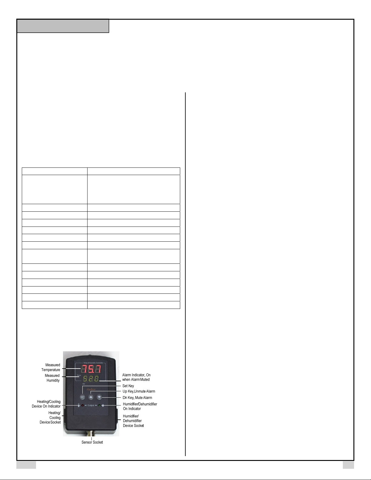
Figure 1. Front Panel.
Measured temperature window: In normal operating mode, this window
shows measured temperature. In parameter setting mode, this window shows
parameter name.
Measured humidity window: In normal operating mode, this window shows
measured humidity. In parameter setting mode, this window shows parameter
value.
Alarm indicator: When the alarm is muted, the alarm indicator (the small dot
on the last digit) will be on.
SET key: Access the program settings and parameter settings.
UP key (Unmute): Increase the value. Press down momentarily to unmute the
alarm.
DOWN key (Mute): Decrease the value. Press down momentarily to mute the
alarm.
Temperature socket: Supply power to heater/cooler.
Temperature indicator: Red LED indicator; it is on when the temperature
socket is energized.
Humidity socket: Supply power to the humidifier/dehumidifier.
Humidity indicator: Green LED indicator; it is on when the humidity socket is
energized.
4. Getting Started
4.1 Power up the controller and connect the sensor
To power up the controller, simply plug its power plug to a wall outlet. Then
connect the 4-pin connector from the humidity sensor to the sensor input port
on the bottom of the controller. Please align the notch on the sensor plug with
the key on the sensor socket. You can refer to the Section 6 in the manual for
details.
4.2 Displayed Information
The top LED window displays the measured temperature, and the bottom LED
window displays the relative humidity reading. If sensor is not connected or
defective, the controller will show “ERR” in its display window.
There is one LED indicator on each side of the controller to show the output
status of each output socket. The red LED on the left is for the temperaturecontrol socket, and the green LED on the right is for the humidity-control
socket.
4.3 Decide the Control Mode for Each Output Socket
The temperature-control socket can be set either to drive a heating device or to
drive a cooling device. This temperature-control mode is determined by the
parameter tCM (tCM), which can be set to “Ht” for heating, or “CL” for
cooling.
Similarly, the humidity-control socket can be set either to drive a humidifying
device or to drive a dehumidifying device. This humidity-control mode is
determined by the parameter hCM (hCM), which can be set to “H” for
humidifying, or “DeH” for dehumidifying.
2019.05 P1/5
Page 2
AUBER INSTRUMENTS WWW.AUBERINS.COM
A
A
A
The user should decide the appropriate configuration for each output socket
based on the user’s particular application. Please refer to section 4.5 and
second 5 for details.
4.4 Change the Setpoints
The setpoint for temperature is TSP (TSP) and the setpoint for humidity is
HSP (HSP). To access the setpoints, simply short-press the SET key, and
then the top window will show TSP and the bottom window will show its value.
Use UP or DOWN arrow keys to adjust the value, and short-press the SET key
again to save the new value and go to the HSP setting. The way to adjust and
save the setting is the same as for temperature setpoint. Once you press the
SET key again, the controller will return to its normal operation mode. Please
see Figure 2 for how to access the setpoints.
Tem p
RH
Normal
Operati ng
Mode
72.0
50.5
SET
Sho rt-pr ess
Tem p
Temp eratur e
75.0
RH
Setp oint
TSP
SET
Sho rt-pr ess
Temp
RH
Humidity
Setp oint
HSP
40.0
SET
Sho rt-pr ess
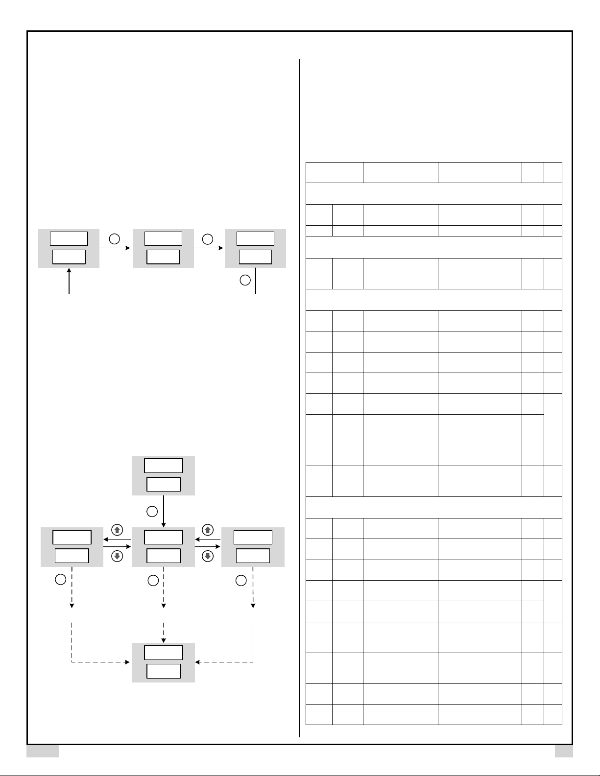
Figure 2. How to access setpoints.
4.5 Adjust Parameters
Other control parameters are grouped into three sub-menus: temperature
(tE), humidity (Hu), and system (SYS)*. To access these parameters, longpress SET key for 3 seconds, the top window will show EDT (EDT). Then use
UP or DOWN arrow key to select the sub-menu item (tE, Hu, or SYS) in the
bottom window, then press SET key again to confirm the selection. Please see
Figure 3 for how to access these parameters. The details for each parameter
are explained in section 5.
Norm al Operati ng Mode
72.0
Temp
50.5
RH
Long- press
SET
3 second s
EDT
Temp
SYS
RH
shor t-press
SET
to confirm
Go th rough all pa ramete rs in
system menu
EDT
Temp
TE
RH
shor t-press
SET
to confirm
Go th rough all pa ramete rs in
temper ature m enu
72.0
Temp
50.5
RH
Norm al Operati ng Mode
EDT
Temp
HU
RH
shor t-press
SET
to confirm
Go th rough all pa ramete rs in
humi dity men u
Figure 3. How to access parameter menus.
5. Parameter Settings
All parameters are listed in Table 1. When a parameter is displayed in the top
window, its value is displayed in the bottom window. The user can use the UP
or DOWN arrow key to adjust the value in the bottom window, then press the
SEK key to save the new value and go to the next parameter. If no key is
pressed for 10 seconds, the controller will exit to its normal operating mode.
Table 1. Parameters.
Code Description Setting Range
Short-press SET Key
tSP tSP Temp. Setpoint
-40ºF ~ 176ºF
80ºC
-40ºC ~
HSP HSP Humidity Setpoint 0 ~ 99.9% RH 40.0 1
Long-press SEK Key
tE: temperature menu
Edt EDT Edit parameters
Hu: humidity menu
SYS*: system menu
C-F C-F Temp. Unit
tCM tCM Temp. Control Mode
TDF
tdF
toF toF
tAH TAH
tAL TAL
Temp. control settings (tE)
Temp. Control
Differential
Temp. Calibration
Offset
Temp. High
Limit Alarm
Temp. Low
larm
Limit
C: Celsius
F: Fahrenheit
Ht: heating mode
CL: cooling mode
0 ~ 50.0 3.0 1
-10.0 ~ 10.0 0 2
-40ºF ~ 176ºF
80ºC
-40ºC ~
-40°F ~ 176ºF
80ºC
-40°C ~
Temp. Anti-short
tAS TAS
Cycle Delay (only for
0 ~ 12 min 0 4
cooling)
ON: output energized
OFF: output de-
energized
tSF TSF
Temp. Sensor
Failure Operation
Humidity control settings (Hu)
HCM HCM
HdF HDF
HoF HoF
HAH HAH
HAL HAL
Humidity Control
Mode
Humidity Control
Differential
Humidity Calibration
Offset
Humidity High Limit
larm
Humidity Low Limit
larm
deH: dehumidifying
H: humidifying
0% ~ 50.0%
-10.0% ~ 10.0% 0% 2
0% ~ 99.9%
0% ~ 99.9%
Humidity Anti-short
HAS HAS
Cycle Delay (only for
0 ~ 12 min 0 4
dehumidifying)
HSF HSF
HdM2 HDM
hdt
HdT2
Humidity Sensor
Failure
Operation
Humidity Output
Delay Mode
Humidity Delay
Timer
ON: output energized
OFF: output de-
energized
0, 1, 2 0 8
0 ~ 999 min 5 9
No
Initi
te
al
75.0 1
tE 6
F 7
CL 1
95.0
3
32.0
OFF 5
H 1
3.0
1
%
90.0
%
3
10.0
%
OFF 5
2019-05 P2/5
Page 3

AUBER INSTRUMENTS WWW.AUBERINS.COM
2
HoS
HOS
Hob2 HOB
Humidity Operating
Setpoint
Humidity Operating
Band
-40°F ~ 176°F 36 10
0°F ~ 200°F 2 10
System setting (SYS)1
PSD1 PSD
Device Access
Password
100 ~ 999 666 11
RST2 RST Factory Reset N, Y N 12
Note 1: The TH220 model doesn’t have SYS menu and the parameter PSD. Only the
TH220-W and TH220A-W have the password parameter PSD.
Note 2: These parameters, HDM, HDT, HOS, HOD, and RST are only available in
TH220A and TH220A-W.
Details About Each Parameter
Note 1. tSP and HSP are the setpoints for temperature-control and humidity-
control respectively. tdF and HdF are the control-differential (i.e., control
hysteresis band) to prevent the load being turned on and off frequently. These
hysteresis bands are one-sided. tCM is the temperature control mode, which
can be set to heating (HT) or cooling (CL). HCM is humidity control mode,
which can be set to humidifying (H) or dehumidifying (dEH).
In the heating mode of the temperature-control channel, the controller will
energize the output socket till the temperature rise to the setpoint tSP; the
output socket will be energized again when the temperature drops below (tSP tDF). In contrast, in the cooling mode of the temperature-control channel, the
controller will energize the output socket till the temperature drops to the
setpoint tSP; the output socket will be energized again when the temperature
rises above (tSP + tDF). Please refer to the Figure 4 below when the output
relay will be turned on.
Temp erature
TSP
(TSP – TDF)
Heat ing Mode
Relay ON
Temperature
(TSP + TDF)
TSP
Time
Figure 4. Temperature output is decided by tSP and tDF.
Similarly, in the humidifying mode of the humidity-control channel, the
controller will energize the output socket till the temperature rise to the setpoint
HSP; the output socket will be energized again when the temperature drops
below (HSP - HDF). In contrast, in the dehumidifying mode of the humiditycontrol channel, the controller will energize the output socket till the humidity
drops to the setpoint HSP; the output socket will be energized again when the
humidity rises above (HSP + HDF). Please refer to the Figure 5 below when
the output relay will be turned on.
Cool ing Mode
Relay ON
Time
Humidity
HSP
(HSP – H DF)
Humidifying
Mode
Relay ON
Humidity
(HSP + H DF)
HSP
Time
Figure 5. Humidity output is decided by HSP and HDF.
Small differential gives tight control. Large differential reduces the frequency of
cycle on and off, and it will extend the life of relay and compressor.
Note 2. toF and HoF are the sensor calibration offset for temperature and
humidity readings respectively. The offset is used to set an input offset to
compensate the error produced by the sensor or input signal itself.
For example, for temperature reading, if the unit displays 37ºF when the actual
temperature is 32ºF, setting parameter toF = - 5 will make the controller display
32ºF.
Note 3. The low limit alarm should be always lower than the high limit alarm.
When the measured temperature is higher than tAH, the temperature high limit
alarm will be on; when the measured temperature is lower than tAL, the
temperature low limit alarm will be on.
Similarly, for humidity readings, when the measured humidity is higher than
HAH, the humidity high limit alarm will be on; when the measured humidity is
lower than HAL, the humidity low limit alarm will be on.
When an alarm is on, the display will be flashing between the measured value
and the alarm type. To mute the alarm, press the DOWN key momentarily.
When the alarm is muted, the alarm indicator (see Figure 1, the small dot on
the last digit) will be lit. If the measured value gets out of the alarm zone then
gets back to the alarm zone again, the alarm will be on again. To resume the
alarm, press the UP key, the alarm indicator should turn off.
To disable the alarm, set High Limit Alarm = Low Limit Alarm. For example,
you can set both tAH and tAL to 32°F, so the temperature alarm will be
disabled.
Note 4. The parameter tAS and HAS are Anti-Short Cycle Delay for cooling
and dehumidifying respectively. The controller is used for cooling or
dehumidifying control, and the load is a compressor, use the parameter tAS or
HAS to prevent the compressor being turned on again when it is at high
pressure (i.e., just after it is turned off). Otherwise, it may shorten the life of
compressor. The Anti-Short Cycle Delay function is used to prevent the rapid
cycling of the compressor. It establishes the minimum time that the output
contact remains open (after reaching cutout) before closing again. The delay
overrides any load demand and does not allow the output contact to close until
the set time-delay value has elapsed. It gives time to release the refrigerant
pressure through evaporator. It is typically set to 4 - 6 minutes.
Note 5. Parameter tSF and HSF are the Sensor Failure Operation for
temperature and humidity control respective, they can be set to ON or OFF.
Dehumidifying
Mo de
Relay ON
Time
2019-05 P3/5
Page 4

AUBER INSTRUMENTS WWW.AUBERINS.COM
When it is set to ON, the output will always be on when the sensor fails; when it
is set to OFF, the output will always be off when the sensor fails.
For example, when the unit controls a refrigerator for food, you may want to set
the tSF to ON if the sensor fails to keep the food cold. When it controls a
heater, you may want to set the tSF to OFF for safety purpose.
Note 6. EDT is the menu-editing parameter. Select tE menu for temperature
control settings; select Hu menu is for humidity control settings, and select
SYS is for system settings. Note: SYS menu is only available to TH220-W,
TH220A, and TH220A-W model.
Note 7. C-F is the parameter to set the temperature unit: C is for Celsius, and
F is for Fahrenheit.
Note 8. The parameter HdM sets the mode for delaying or constraint the
humidity output. It has three available modes, which are listed and explained in
the table below.
Table 2. Humidity output delay mode.
HdM Mode Details
0 No delay Default value. No delay or constraint on the
humidity output.
1 Time-delay Delay the humidity output by a timer set by HdT.
2 Temperature-
range
In situations such as controlling a curing chamber converted from a fridge,
there is usually a big decrease in the relative humidity (RH%) whenever the
compressor of the fridge is working. Also, there can be big increase in the
relative humidity when the user opens the door of the fridge. This kind of
change in RH% can gradually recover. However, if the controller’s humidity
control kicks in right away, it creates in a big swing in the RH%.
Using time-delay (HdM = 1) or temperature-range constraint (HdM = 2) can
help users to reduce the RH% swing.
Note 9. The parameter HdT sets the delay timer for humidity output, it can be
set from 0 to 999 minutes. When HdM is set to “1”, the output to the humidity
control will be delayed for a time period set by HdT.
Please note, the HdT is effective in both humidifying and dehumidifying mode.
In dehumidifying mode, the actual delay time of the humidity output is decided
either by either HAS or HdF, whichever is longer.
Note 10. The parameter HoS and Hob set up a temperature range within
which the humidity output is enabled. HoS defines a temperature setpoint for
enabling humidity output, i.e., a lower boundary; and Hob defines the
temperature band. Please see the diagram in Figure 6 for how these two
parameters affect the humidity output.
For example, when HdM = 2, HoS = 36°F, and HoB = 2°F, that means when
the temperature is below 36°F or above 38°F the humidity output won’t be
activated even when the controller calls for output to the humidity channel.
Allow humidity output only when the temperature is
within a range defined by parameter HoS and
HoD.
Figure 6. When the humidity output delay mode is HdM = 2, the humidity
output is allowed only when the temperature is within the range set by HoS and
Note 11. PSD is the Device Access Password (only available to TH220-W and
TH220A-W model). This parameter is used to lock the access to parameter
settings on AuberSmart app.
Note 12. RST is the reset parameter. Choose “n” to take no action. Chose “y”
to reset all parameters back to factory settings.
6. How to install the sensor to the unit.
The connector of sensor contains a slot for fitting pin connection. It locates at
the bottom of the controller. It also has a spring lock to prevent disconnections
from accidental pulling on the cable.
To install the sensor to the controller: 1) Identify the key on the male sensor
connector (Figure 7, a) and the notch on the female connector (Figure 7, b). 2)
Hold the tail of the female connector, align the notch and the key, and push the
female connector forward.
To remove the connector, hold the spring-loaded collar on the female
connector and pull it back. Please see Figure 8.
Temp eratur e
(HoS + H ob)
HoS
Humidity output enabled
HoD.
Time
(a)
2019-05 P4/5
Page 5

AUBER INSTRUMENTS WWW.AUBERINS.COM
(b)
(c)
Figure 7. Install the sensor.
Figure 8. Remove the sensor.
Auber Instruments
5755 North Point Parkway, Suite 99
Alpharetta, GA 30022, USA
www.auberins.com
E-mail: info@auberins.com Tel: 770-569-8420
Copyright 2007-2019, Auber Instruments All Rights Reserved.
No part of this manual shall be copied, reproduced, or transmitted in any way
without the prior, written consent of Auber Instruments. Auber Instruments
retains the exclusive rights to all information included in this document.
2019-05 P5/5
 Loading...