

Page 1
AUBER INSTRUMENTS WWW.AUBERINS.COM
2017.10 P1/3
TH220 TEMPERATURE AND HUMIDITY CONTROLLER
INSTRUCTION MANUAL
Version 1.2 (Oct, 2017)
1. Overview
This plug-n-play temperature and humidity controller is designed for high
relative humidity (>85%) and condensing environments, where slight
temperature drop may cause condensation and could damage the sensor. This
controller equipped with one of the most robust humidity sensors on the
market. It can be fully recovered even immersed in water. Ideal for curing
Fridge. The controller can control both temperature (heating or cooling) and
humidity (humidifying or dehumidifying) at the same time.
2. Specification
Table 1. Specifications
Temperature Control Range
- 40 ~ 80 ° C, - 40 ~ 176 °F
Temperature Resolution
0.1 ° C (between -9.9 ~ 80 °C)
1 ° C (between -40 ~ 10 °C)
0.1 ° F (between -9.9~99.9 °F)
1 ° F (between -40 ~ 10 °F,100 ~176 ° F)
Temperature Accuracy
0.5 °C
Temperature Control Mode
On/Off Control. Heating or Cooling
Temperature Control Output
15A, 120V or 240V AC *
Humidity Control Range
0~99.9% RH
Humidity Resolution
0.1% RH
Humidity Accuracy
4% RH
Humidity Control Mode
On/off control.
Humidifying or dehumidifying
Humidity Control Output
15A, 120V or 240V AC *
Operating Temperature
0~50 °C
Dimension
91x140x46mm
Input Power
85 ~242VAC, 50Hz/60Hz
Sensor Cable Length
6 ft (2m)
Power Cable Length
3 ft (1m)
* Please note: Although both temperature and humidity output can handle up to
15A, the combined total power of the two channels are limited to 1500 Watts
due to the limitation of input power cord.
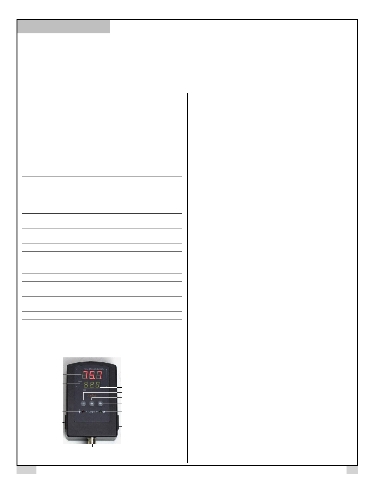
3. Front Panel
Up Key,Unmute Alarm
Dn Key, Mute Alarm
Set Key
Heating/
Cooling
Device Socket
Humidifier/
Dehumidifier
Device Socket
Humidifier/Dehumidifier
On Indicator
Heating/Cooling
Device On Indicator
Measured
Humidity
Measured
Temperature
Alarm Indicator, On
when Alarm Muted
Sensor Socket
Figure 1. Front Panel
Measured temperature window: In normal operating mode, this window
shows measured temperature. In parameter setting mode, this window shows
parameter name.
Measured humidity window: In normal operating mode, this window shows
measured humidity. In parameter setting mode, this window shows parameter
value.
Alarm indicator: When the alarm is muted, the alarm indicator (the small dot
on the last digit) will be on.
SET key: Access the program settings and parameter settings.
UP key (Unmute): Increase the value. Press down momentarily to unmute the
alarm.
DOWN key (Mute): Decrease the value. Press down momentarily to mute the
alarm.
Temperature socket: Supply power to heater/cooler.
Temperature indicator: Red LED indicator; it is on when the temperature
socket is energized.
Humidity socket: Supply power to the humidifier/dehumidifier.
Humidity indicator: Green LED indicator; it is on when the humidity socket is
energized.
4. Setup Flow Chart
When the controller is powered on, it will display the measured
temperature and humidity. The controller will keep running according to the
saved setting. If the humidity or temperature sensor is shorted/disconnect, the
controller will display “Err”. Please see Figure 2 and 3 for the flow chart to set
the parameters.
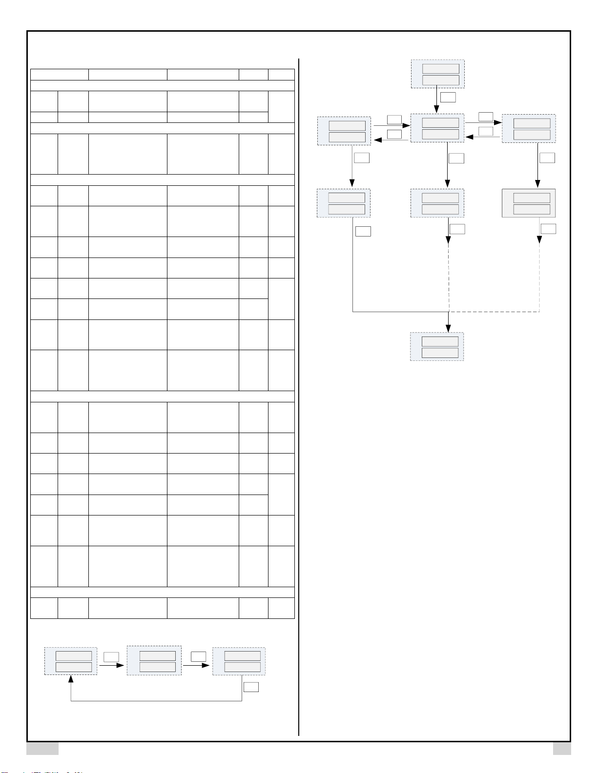
5. Parameter Settings
To change the target temperature or humidity, press SET key momentarily.
The controller will show tSP (temperature set point), press SET again will show
HSP (humidity set point). Use Up or Down key to change the tSP or HSP. See
Figure 2 for details.
To change the other parameters, press SET key for 3 seconds, the RH window
(bottom window) will show tE, Hu or SYS* (depending on which menu was set
last time). tE menu is for temperature control settings; Hu menu is for humidity
control settings and SYS* is for system settings. Press Down (or Up) key to
change the RH window to Hu (or tE, SYS), which is the current selected menu,
then press SET key to enter.
To change parameter settings, in the parameter setup mode, use Up or Down
key to modify the parameter value. Then press SET key again to confirm the
change. This instrument will automatically exit if no key is pressed for 10
seconds. Please see the Table 1 for the parameters.
* Menu SYS and parameter PSD are only applicable for TH220-W model.
Instruction Manual
Page 2
AUBER INSTRUMENTS WWW.AUBERINS.COM
2017.10 P2/3
Table 1. Parameters Description
Code
Description
Setting Range
Initial
Note
Menu for set point (Figure 2)
tSP
tSP
Temp. Set Point
-40~176 ºF
-40~80 ºC
75.0
1
HSP
HSP
Humidity Set Point
0~99.9 %RH
40.0
Menu for parameters (Figure 3)
Edt
EDT
Menu Selection
tE: Temp. Menu
Hu: Humidity Menu
SYS*: System
Menu
TE
6
Temp. control settings (Edt = tE)
C-F
C-F
Temp. Unit
C: Celsius
F: Fahrenheit
F
tCM
tCM
Temp. Control Mode
Ht: Heating Control
CL: Cooling
Control
CL
TdF
TDF
Temp. Control
Differential
0~50.0
3.0 1 toF
toF
Temp. Calibration
Offset
-10.0~10.0
0
2
tAH
TAH
Temp. High
Limit Alarm
-40~176 ºF
-40~80 ºC
95.0
3
tAL
TAL
Temp. Low
Limit Alarm
-40~176 ºF
-40~80 ºC
32.0
TAS
TAS
Temp. Anti-short
Cycle Delay (only for
cooling)
0~12 min
0
4
TSF
TSF
Temp. Sensor
Failure Operation
ON: Output
energized
OFF: Output de-
energized
OFF
5
Humidity control settings (Edt = Hu)
HCM
HCM
Humidity Control
Mode
deH:
Dehumidifying
H: Humidifying
H
HdF
HDF
Humidity Control
Differential
0~50.0
3.0 1 HoF
HoF
Humidity Calibration
Offset
-10.0~10.0
0 2 HAH
HAH
Humidity High Limit
Alarm
0~99.9
90.0 3 HAL
HAL
Humidity Low Limit
Alarm
0~99.9
10.0
HAS
HAS
Humidity Anti-short
Cycle Delay (only for
dehumidifying)
0~12 min
0
4
HSF
oFF
Humidity Sensor
Failure
operation
ON: Output
energized
OFF: Output de-
energized
OFF
5
System setting (Edt = SYS*)
PSD
PSD
Device Access
Password
100 ~ 999
666
7
SET
T
RH
tSp
5 4.2
T
RH
1 5.0
HSp
RH
T
6 8.9
3 6.8
SET
Humidity Set PointTemp. Set Point
SET
Figure 2. Flow Chart Part 1
6 8.9
3 6.8
3 sec
T
RH
Edt
tE
T
RH
Edt
Hu
T
RH
C-F
F
T
RH
HcM
deH
T
RH
Dn
Up
6 8.9
3 6.8
T
RH
SET
SET
SET
SET
Temp.
Unit
Humidity
Control
Settings
Humidity
Control
Mode
Temp.
Control
Settings
Edt
sys
T
RH
Dn
Up
SET
System
Setting*
psd
666
T
RH
Access*
Password
SET
SET
Figure 3. Flow Chart Part 2
Note 1. For heating (or humidifying), the output will be off when the
temperature (or humidity) reaches the set point; it will be on again when the
temperature (or humidity) drops down to tSP - tdF (or HSP - HdF).
For cooling (or dehumidifying), the output will be off when the temperature (or
humidity) reaches the set point; it will be on again when the temperature (or
humidity) rises to tSP + tdF (or HSP + HdF).
Small differential gives tight control. Large differential reduces the frequency of
cycle on and off, and it will extend the life of relay and compressor.
Note 2. The offset is used to set an input offset to compensate the error
produced by the sensor or input signal itself.
For example, for temperature reading, if the unit displays 37 ºF when the actual
temperature is 32ºF, setting parameter toF = - 5 will make the controller display
32ºF.
Note 3. The low limit alarm will be always lower than the high limit alarm. When
the measured temperature (humidity) is higher than tAH (HAH), the
temperature (humidity) high limit alarm will be on; when the measured
temperature (humidity) is lower than tAL (HAL), the temperature (humidity) low
limit alarm will be on.
When alarm is on, the display will be flashing between the measured value and
alarm type. To mute the alarm when it is on, press the Down key momentarily.
When the alarm is muted, the alarm indicator (see Figure 1, the small dot on
the last digit) will be on. If the measured value gets out of the alarm zone then
Page 3

AUBER INSTRUMENTS WWW.AUBERINS.COM
2017.10 P3/3
gets back to the alarm zone again, the alarm will be on again. To resume the
alarm, press the Up key, the alarm indicator will be off.
To disable the alarm, set High Limit Alarm = Low Limit Alarm.
Note 4. When The controller is used for cooling (or dehumidifying control) and
load is a compressor, it should not turn on the compressor when it is at high
pressure (just after turned off). Otherwise, it may shorten the life of
compressor. The Anti-Short Cycle Delay function can be used to prevent the
rapid cycling of the compressor. It establishes the minimum time that the output
contact remains open (after reaching cutout) before closing again. The delay
overrides any load demand and does not allow the output contact to close until
the set time-delay value has elapsed. It gives time to release the refrigerant
pressure through evaporator. It is typically set to 4-6 (minutes).
Note 5. The TSF (HSF) can be set to ON or OFF. When it is set to ON, the
output will always be on when the sensor fails; when it is set to OFF, the output
will always be off when the sensor fails.
For example, when the unit controls a refrigerator for food, you may want to set
the TSF to ON if the sensor fails to keep the food cold. When it controls a
heater, you may want to set the TSF to OFF for safety purpose.
Note 6. Menu selection parameter. tE menu is for temperature control settings;
Hu menu is for humidity control settings and SYS is for system settings. SYS
setting is only available to TH220-W model.
Note 7. Device access password (only available to TH220-W model). This
parameter is used to lock the access to parameter settings on AuberSmart
app. Please refer to figure 3.
6. How to install the sensor to the unit.
The connector of sensor contains a slot for fitting pin connection. It locates at
the bottom of the controller. It also has a spring lock to prevent disconnections
from accidental pulling on the cable.
To install the sensor to the controller: 1) Identify the key on the male sensor
connector (Figure 4, a) and the notch on the female connector (Figure 4, b). 2)
Hold the tail of the female connector, align the notch and the key, and push the
female connector forward.
To remove the connector, hold the spring-loaded collar on the female
connector and pull it back. Please see Figure 5.
(a)
(b)
(c)
Figure 4. Install the sensor.
Figure 5. Remove the sensor.
Auber Instruments
5755 North Point Parkway, Suite 99
Alpharetta, GA 30022, USA
www.auberins.com
E-mail: info@auberins.com Tel: 770-569-8420
Copyright 2007-2017, Auber Instruments All Rights Reserved.
No part of this manual shall be copied, reproduced, or transmitted in any way
without the prior, written consent of Auber Instruments. Auber Instruments
retains the exclusive rights to all information included in this document.
 Loading...