

Page 1
AUBER INSTRUMENTS WWW.AUBERINS.COM
Instruction Manual
TH100ACHIMDX Thermometer
for Stove Pipe, Chimney, w/ remote alarm
1. Features
Thi s thermometer can be used for stove pipe and chimney temperature monitoring.
The meter contains two alarm settings for the built-in buzzer. One can be used for high
limit alarm and the other can be used for low fuel alarm. It also has a third alarm for
the connected external buzzer that can be placed at different floor from where the
stove is located. The gauge is powered by 12V DC through an AC adapter (included)
for continuous operation. It can also be powered by car battery.
2. Specifications
AC adaptor: 100-240V, 50/60Hz input. 12 VDC, 1 Amp output.
Power consumption: <2W
Sampling rate: 4 samples/second
Accuracy: 0.2% full scale
Sensor: K type thermocouple, -320-1800°F (-200~900°C).
Output for buzzer: 12VDC, 1 Amp
LED display: 0.39 inch, red
Internal buzzer: Two set points alarm.
External buzzer: High limit or low limit alarm
Dimension: 3x5x1.2" (78x120x28.5mm)
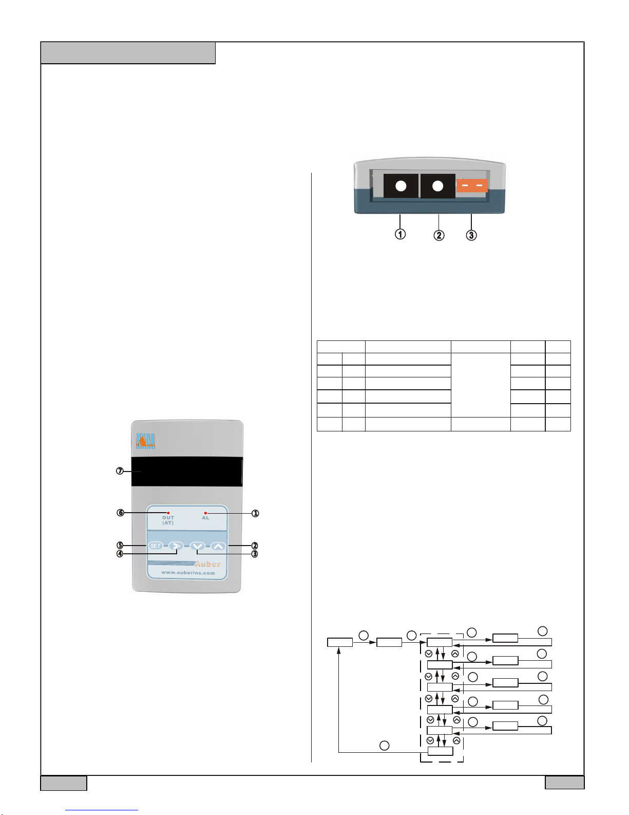
3. Front Panel
8888
Version 1.1
POWER - 12V Power supply input
OUT - Output for external buzzer
INPUT - Temperature probe input
Figure 2. Terminals (back view)
5. Parameter Setting
5.1. Temperature setting and Alarm setting (accessed by code 0001)
Table 1. Alarm parameters
Symbol
SV
SV
AH1
AH1
AL1
AL1
AH2
AH2
AL2
AL2
End
End
Note 1. Set Alarm for external buzzer.
There are two ways to set the external alarm temperature.
a. During the normal operation mode, press Λ or V once to switch the display from
process value (PV) to set value (SV, or target temperature). The display will start to
blink. Press Λ or V again to increase or decrease the SV. When finished, wait 8
seconds and the settings will take effect automatically (the display will stop blinking).
b. Press SET key once. Use >, Λ and V keys to enter code 0001. Press SET key to
confirm, then the display would be SV (Su). Press SET key again to display the SV
setting. Use >, Λ and V keys to enter the new SV value and press SET to confirm.
Press V k ey to change the display to END. Then, press SET to exit. You can also
ignore t he steps after confirmation of SV. The controller w ill return to normal operation
mode automatically if no key is pressed for 1 minute. The flow chart below shows how
to set the SV and alarms in details.
Description
External alarm temperature
Alarm 1 on temperature
Alarm 1 off temperature
Alarm 2 on temperature
Alarm 2 off temperature
Exit
Range
Arbitrary value
within the
measuring range
Initial
480
481
480
250
250
Note
Note 1
Note 2
Figure 1. Front panel
AL - Internal Alarm Indicator
Value increment / Select next parameter
Value decrement / Select previous parameter
Digit shift / Internal alarm mute
Set / Confirm
OUT - External buzzer indicator
Parameter display
4. Connecting the meter
Figure 2 shows the terminals of the meter. Connect the 12V DC power adapter to the
terminal 1 and wall outlet. Connect the external buzzer connector to terminal 2. The
polarity for this socket is center pin positive (+), outer collar negative ( ). Connect the
K thermocouple to terminal 3. Please note that thermocouple connector also has
polarity. The wide blade should go to the wide slot.
2013.05
The default setting for the external buzzer is high limit alarm (see Note 6). The external
buzzer will be on when the tempeature is above SV+Hy (see Note 5), will be off when
the temperature drops back to SV.
Operation Mode
XXXX
Enter Code
SET SET
0001
SET
Parameter Display
sv
ah1
al1
ah2
al2
end
External buzzer Tem
SET
Buzzer On Temp
SET
Buzzer Off Temp
SET
Buzzer On Temp
SET
Buzzer Off Temp
SET
480
0250
0249
0250
0250
SET
SET
SET
SET
SET
Figure 3. Flow chart for how to set target temperature and alarm.
P1/2
Page 2
AUBER INSTRUMENTS WWW.AUBERINS.COM
Note 2. Set alarm for internal buzzer
The meter offers two alarms that can be set to turn on the internal buzzer at specific
temperatures. The first alarm is controlle d by parameter s AH1 and AL1. The initial
setting will turn on the buzzer at 481 °F and off when temperature drops below 480°F.
The second alarm is controlled by parameters AH2 and AL2. The initial setting of the
second alarm is deactivated. It can be set as low alarm to send warning.
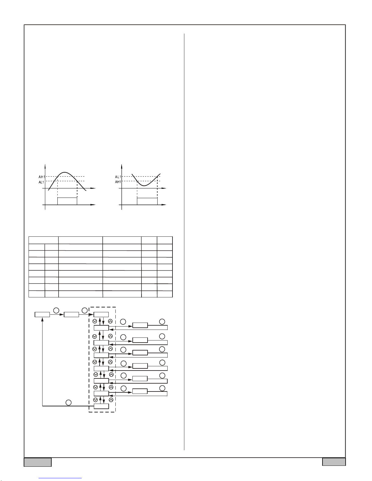
AH1 and AH2 are the temperatures to turn the inernal buzzer on; AL1 and AL2 are the
temperatures to turn buzzer off. When AH1(2) >AL1(2), the alarm is set for absolute
high alar m as shown in Figure 4 below. When AH1(2) <AL1(2), the alarm is set for
absolute low alarm as shown in Figure 5 below. When AH1(2)=AL1(2), the alarm is
deactivated.
Example, if AH1=481, AL1=480, when the temperature goes up to 481°F, the buzzer
will be on; when the tempe rature drop s do wn to 480°F, the bu zzer wi ll be o ff. If
AH2=180, AL2=185, when the temperature drops down to 180°F, the buzzer will be
on; when the temperature goes up to 185°F, the buzzer will be off.
User can press the shift key (>) to temporarily mute the buzzer sound. The alarm will
buzz again if the alarm set temperature is reached again. To permanently deactivate
the alarm, set AH1=AL1 or AH2=AL2. Please see flow chart in Figure 3 on how to set
the value.
The default se tting is both in tern a l and external bu zzer are on when the
temperature is above 481 (SV+Hy, AH1); will be off when the temperature drops
down to 480 (SV, AL1).
Note 5. Calibration offset, PSb is used to set an input offset to compensate the error
produced by the sensor. For example, if the meter displays 5 º C when pro be is in
ice/water mixture, setting PSb= -5, will make the controller display 0 ºC.
Note 6. Rd is for system function selection, Its value should be kept as 1 for high limit
alarm.
Note 7. Display unit selection CorF: 0 for Celsius (°C); 1 for Fahrenheit (°F).
Additional note:
The remote alarm control output of this thermometer can also be used as a PID or
on/off control output. For details, please refer to Auber SYL-1614 manual.
PV
Buzzer on Buzzer on
PV
Figure 4. Absolute high alarm Figure 5. Absolute low alarm
5.2 System Configuration Parameters (accessed by code 0089)
Table 3. System configuration parameter setting
Code Setting Range
inty
Inty
outy
outy
Hy
hy
atdu
Atdu
psb
PSb
rd
rd
corf
CorF
end
End
Operation Mode
XXXX
Description
Input Sensor Type
Output Mode
Hysteresis Band
1
0, 1, 2, 3, 4, 5, 6
Ignore this setting
Input Offset
External alarm type
Display Unit
Exit
Parameter Display
Enter Code
SET SET
0089
inty
outy
See Appendix
0~9999
0~200
-1000~1000
0: low 1: high
0: ° C 1:°F
HY
atdu
psb
rd
corf
SET
end
SET
SET
SET
SET
SET
SET
Initial Note
K
3
0
1
1
Output mode selection
X
Hysteresis Band
XXXX
Autotune offset
X
Input offset
XXXX
Heating/Cooling
X
Display Unit(C/F)
X
Note 3
Note 4
Note 5
Note 6
Note 7
SET
SET
SET
SET
SET
SET
Figure 6. The system setup flow chart
Note 3. The value of outy should be 3.
Note 4. The default setting for the external buzzer is high limit alarm. The external
b u z z er wi l l be on when the tempeature is above SV+Hy will be off when the
temperature drops back to SV. The default setting for the Hy is 1.
2013.05
Auber Instruments, Inc
5755 North Point Parkway, Suite 99
Alpharetta, GA 30022 USA
Tech support: 770-569-8420, 404-983-8228
Copyright 2007-2016, Auber Instruments All Rights Reserved.
No part of this manual shall be copied, reproduced, or transmitted in any way
without the prior, written consent of Auber Instruments. Auber Instruments
retains the exclusive rights to all information included in this document.
P2/2
 Loading...