

Page 1
AUBER INSTRUMENTS WWW.AUBERINS.COM
2019.08 P1/4
TD120-W WIRELESS TEMPERATURE CONTROLLER
INSTRUCTION MANUAL
Version 1.0 (August, 2019)
1. Overview
This temperature controller contains one temperature probe and two
independent outputs. One output is for cooling device such as
refrigerator and the other one is for heating device. It can be used for
applications such as beer fermentation or convert a refrigerator to
kegerator. By using both cooling and heating devices, the refrigerator
can be controlled at specific temperature regardless in hot summer or
cold winter.
This controller is a plug-and-play controller. No wiring is needed for the
heater or cooler. Both heating and cooling control modes are simple
on/off control, similar to a mechanical thermostat but with much higher
precision due to adjustable hysteresis band, precise sensor and digital
readout. Anti-short function is provided for cooling to protect the
compressor from being turned on with high pressure Freon.
Different operation temperature ranges of the two outputs can be set
separately. Once the cooling range is set, the controller program will
automatically limit the heating range to prevent both heating and
cooling from being turned on at the same time.
A digital silicon band gap sensor is used. The advantage is being much
more reliable in moisture environment than thermistor sensor. It can be
immersed over extended period of time. It also has a more uniform
accuracy over an entire specified temperature range.
Reversed logic function has been added to this model, which can
activate the one single output when temperature is in a range set by
HSP (heating setpoint) and CSP (cooling setpoint). For details, see
note 7 on page 3.
2. Specification
Temperature
Control Range
-50 ~ 105° C, -58 ~ 221°F
Temperature
Resolution
0.1 ° C (between -9.9 ~ 99° C)
1 ° C (between -50 ~ -10° C, 100 ~ 120° C)
0.1 ° F (between -9.9 ~ 99.9° F)
1 ° F (between -58 ~ -10° F, 100 ~ 248° F)
Temperature Accuracy
0.5 ° C or 0.9 ° F
Temperature Control
Mode
On/Off Control. Heating and Cooling
Temperature Control
Output
10A, 120V or 240V AC*
Audio Alarm
High and Low Limit
Sensor Type
Silicon Band Gap Sensor
Ambient Temperature
0 ~ 120° F (-20 ~ 50° C)
Dimension
91 x 140 x 46 mm
Input Power
85 ~ 242V AC, 50Hz/60Hz
Power Cable Length
3 ft (1m)
Warranty
1 Year for the controller
*: Either the heating or the cooling device is limited to 10 Amps. The output voltage is the
same as the input voltage. When the controller is plugged into 120V AC, the output will
be 120V AC. If the controller is connected to 240V AC, the output will be 240V AC also.
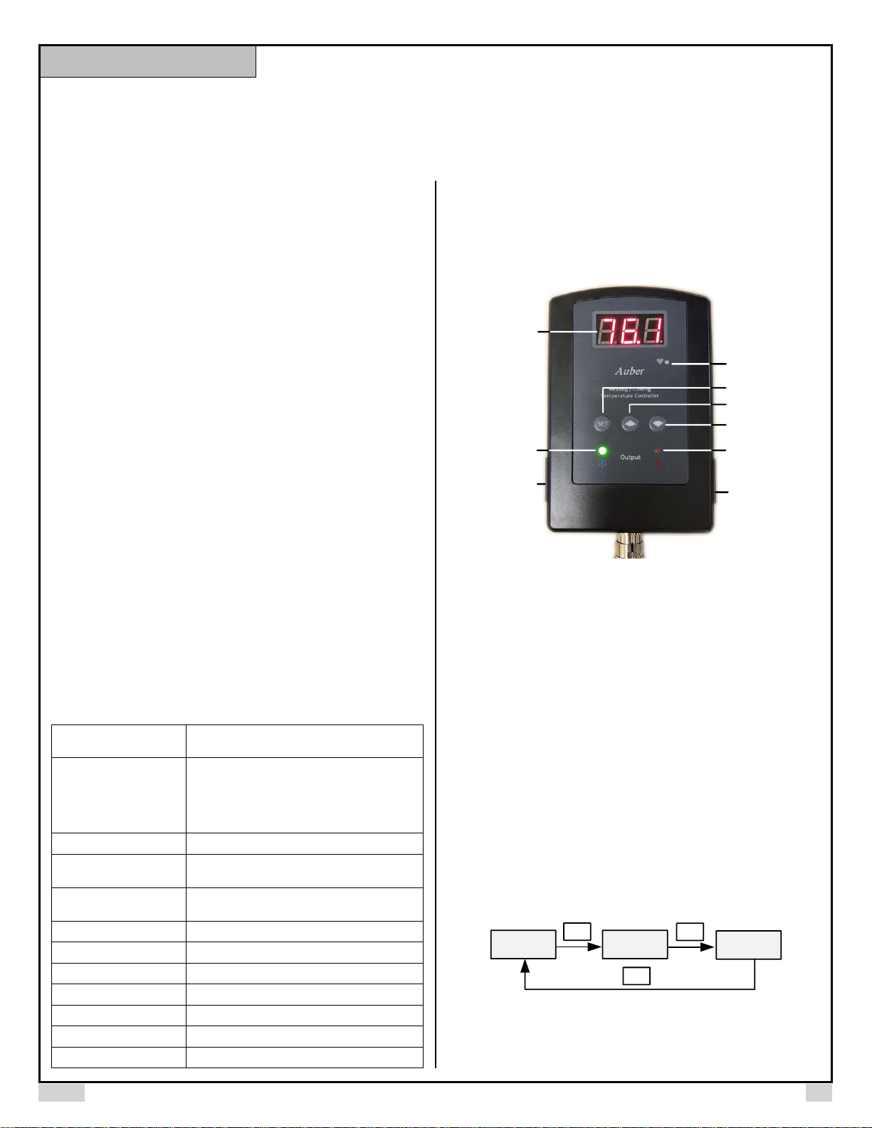
3. Front Panel
Up Key
Dn Key, Mute Alarm
Set Key
Cooling Device
Socket
Heating Device
Socket
Heating device
On Indicator
Cooling Device
On Indicator
Measured
Temperature
Sensor Socket
WIFI Indicator
Figure 1. Front Panel
4. WIFI Function
To reset the WIFI function of this controller, push down and hold SET
key and down arrow key at same time for about 3s. Then WIFI
indicator will be fast blinking (4 Hz). It indicates this controller is waiting
for new setup now. After the controller is setup to your phone
successfully, the WIFI indicator will be OFF at most of the time. For
details, see supplementary manual for details.
5. Setup Flow Chart
When the controller is powered on, it will display the measured
temperature. The controller will keep running according to the saved
setting. If the temperature sensor is shorted/disconnected, the
controller will display “Err”. Please see Figure 2 for the flow chart to set
the parameters.
SET
6 8.9
SET
CSP
HSP
Measured
Temp
Cooling
Set Point
Heating
Set Point
SET
Figure 2. Flow Chart Part 1
Instruction Manual
Page 2

AUBER INSTRUMENTS WWW.AUBERINS.COM
2019.08 P2/4
6 8.9
5 sec
SET
AH
SET
AL
SET
CDF
SET
HDF
SET
6 8.9
Alarm High Limit
Alarm Low Limit
Cooling Differential
Heating Differential
Measured
Temperature
Figure 3. Flow Chart Part 2
6. Parameter Settings
To change the target temperature (set points), press SET key
momentarily. The controller will show CSP (Cooling set point), press
SET again will show HSP (heating set point). When the controller
shows CSP or HSP, use Up or Down key to change the value. Then
press SET key to confirm the change. See figure 2 for details
To change the system parameters, press SET key for 5 seconds, the
controller will enter the parameter set up mode. The first parameter AH
will show on the display. Use Up or Down key to modify the parameter
value. Then press SET key to confirm the change. The display will
show the parameter again. Press the SET key to show the next
parameter. The instrument will automatically exit if no key is pressed
for 10 seconds. See figure 3 & table 1 for details.
Note 1. For cooling (or heating), the output will be off when the
temperature is below (or over) the set point; will be on again when the
temperature rises up (or drops down) to CSP + CdF (or HSP - HdF).
The maximum value of the HSP can be set is the current value of CSP.
But CSP can be set to the value between -58 ~ 248ºF or -50 ~ 125ºC.
When the CSP is set to a value lower than current HSP, the HSP will
be adjusted to the CSP value automatically.
For example, when CSP = 67.0ºF, HSP = 62ºF, HSP can be set to any
value between -58ºF and 67.0ºF. For CSP, it can still be set to any
value between -58º F and 248ºF. If you set it to 55.0, the HSP will be
adjusted to 55.0ºF automatically.
Small differential gives tight control; large differential reduces the
frequency of cycle on and off. It will extend the life of relay and
compressor.
Table 1. Parameters Description
Code
Symbol
Description
Setting range
Initial
Note
Menu for set points (Figure 2)
CSP
CSP
Cooling Set Point
-58 ~ 248ºF
-50 ~ 125ºC
67.0
1
HSP
HSP
Heating Set Point
-58 ~ CSPºF
-50 ~ CSPºC
62.0
Menu for parameters (Figure 3)
AH
AH
Alarm High Limit
-58 ~ 248ºF
-50 ~ 125ºC
95.0
2
AL
AL
Alarm Low Limit
-58 ~ AHºF
-50 ~ AHºC
34
CdF
CDF
Cooling Differential
0 ~ 50.0ºF
3.0
1
HdF
HDF
Heating Differential
0 ~ 50.0ºF
0.0
AS
AS
Cooling Antishort
0 ~ 12 min
0
3
SFA
SFA
Sensor Failure
Operation
0-0, 0-1, 1-0
0-0
4
oFS
OFS
Temperature Offset
0 ~ 10.0
0
5
C-F
C-F
Temperature Unit
C: Celsius
F: Fahrenheit
F 6 LGC
lgc
Logic Control
nor, r-C, r-H
nor
7
rST
rst
Factory Reset
no, YES
No
8
PSd
psd
Device Access
Password
000~777
777
9
Note 2. When the measured temperature is higher than AH, the high
limit alarm will be on; when the measured temperature is lower than AL,
the low limit alarm will be on.
When alarm is on, the display will be flashing between the measured
value and alarm type. To mute the alarm when it is on, press the Down
key momentarily. If the measured value gets out of the alarm zone then
gets back to the alarm zone again, the alarm will be on again. To
disable the alarm, set AH the same value as AL (AH = AL).
The maximum value of the AL can be set is the current value of AH.
But AH can be set to the value between -58 ~ 248ºF or -50 ~ 125ºC.
When AH is set to a value lower than current AL, the AL will be
adjusted to the AH value automatically.
For example, when AH = 95.0ºF, AL = 32º F, AL can be set to any value
between -58º F and 95.0ºF. For AH, it can be set to any value between
-58ºF and 248ºF. If you set it to 25.0ºF, the AL will be adjusted to
25.0ºF automatically.
Note 3. The Cooling Anti-short is the delay time to turn the cooling load
on. When the controller is used for cooling and load is a compressor, it
should not turn on the compressor when it is at high pressure (just right
after it turned off). Otherwise, it may shorten the life of the compressor.
The Anti-short cycle delay function can be used to prevent the rapid
cycling of the compressor. It establishes the minimum time that the NO
Page 3

AUBER INSTRUMENTS WWW.AUBERINS.COM
2019.08 P3/4
contact remains open (after reaching cutout) before closing again. The
delay overrides any Load Demand and does not allow the NO contacts
to close until the set time-delay value has elapsed. It gives time to
release the refrigerant pressure through evaporator. It is typically set to
4 ~ 6 minutes.
Note 4. The SFA defines how the output would be if the sensor fails. It
can be set to 0-0, 0-1 or 1-0. Please refer to table 2 for details.
Table 2. Output of the controller when sensor fails:
SFA
Controller output when sensor fails
0-0
cooler off, heater off
1-0
cooler on, heater off
0-1
cooler off, heater on
For example, when the unit controls a refrigerator for food, you may
want to set the SFA to ON if the sensor fails to keep the food cold.
When it controls a heater, you may want to set the output to OFF for
safety purpose.
Note 5. The offset is used to set an input offset to compensate the
error produced by the sensor or input signal itself.
For example, for temperature, if the unit displays 37ºF when the actual
temperature is 32ºF, setting parameter oFS = -5 will make the
controller display 32ºF.
Note 6. C-F determines the temperature unit. It can be set to C
(Celsius, ˚C) or F (Fahrenheit, ˚F).
Note 7. LGC Control Logic (advanced feature). This parameter is used
to change the current control logic mode. Three modes are available:
• NOR -- normal control logic (default)
• R-C -- reverse logic, output send to Cooling socket (left)
• R-H -- reverse logic, output send to Heating socket (right)
If set to default mode (NOR), when this controller is calling for heat, the
heating output socket on the right will be triggered. When this controller
is calling for cool, the cooling output socket on the left will be triggered.
If set to reverse modes (R-C/R-H), when this controller is calling for
heat or cool, the output is disabled. In other conditions, the output will
be triggered. You can assign this output to cooling socket (R-C), or
heating socket (R-H). For details, see flow chart below.
Figure 4. Reverse mode flow chart.
Explanation:
1. The plot on the top shows how the room temperature changes as
time goes by. The diagram on the bottom shows the status of the
output relay as temperature move across each set point.
Page 4

AUBER INSTRUMENTS WWW.AUBERINS.COM
2019.08 P4/4
2. There are two Set Points -- CSP and HSP. Each Set Point has its
own output relay, Cooling Relay and Heating Relay. Each Set Point
has a control differential value, CdF or HdF.
3. In the Reverse Logic mode, user can choose to use either the
Cooling Relay (output socket on the left) or the Heating Relay (output
socket on the right) to drive an external load.
4. In the Reverse Logic mode, the relay will be energized when the
probe reading is within the temperature range set by CSP (75° F) and
HSP (32° F) as well as their differential bands CdF and HdF.
Note 8. rST is the factory reset parameter. Choose “Yes” to reset all
the parameters back to factory settings.
Note 9. PSd is the device access password (only available to TD120W model). This parameter is used to lock the access to parameter
settings on Aubersmart App.
7. How to install the sensor to the unit.
The connector of sensor contains a slot for fitting pin connection. It also
has a spring lock to prevent disconnections from accidental pulling on
the cable. To install the sensor to the controller: 1) identify the key on
the male connector (Figure 5, a) and the notch on the female connector
(Figure 5, b); 2) hold the tail of the female connector, align the notch
and the key, and push the female connector forward (Figure 5, c). To
remove the connector, hold the spring-loaded collar on the female
connector and pull it back. Please see Figure 6.
(a)
(b)
(c)
Figure 5. Install the sensor.
Figure 6. Remove the sensor.
Auber Instruments Inc.
5755 North Point Parkway, Suite 99,
Alpharetta, GA 30022
www.auberins.com
E-mail: info@auberins.com Tel: 770-569-8420
Copyright 2007-2019, Auber Instruments All Rights Reserved.
No part of this manual shall be copied, reproduced, or transmitted in any way
without the prior, written consent of Auber Instruments. Auber Instruments
retains the exclusive rights to all information included in this document.
 Loading...