

Page 1
AUBER INSTRUMENTS WWW.AUBERINS.COM
Instruction Manual
SYL-2813A Dual-Input Automotive Multimeter
Version 1.6 (Mar, 2019)
A. Specifications
Table 1. Specifications of SYL-2813A Automotive Multimeter.
Power Supply
DC 12 -30 V (Isolated)
Power Consumption < 2 Watt
Relay Contact Rating 3 A at 220 VAC
Input Type Thermocouple: K, E, S, R, J, T, B, WRe3/25.
Resistance: Pt100, Cu50, (375R)*
Voltage: 75 mV, 30 mV, 0 - 5V, 1 - 5V, 10 V
Amperage: (0 - 10 mA, 0 - 20 mA, 4 - 20 mA)*
Input Channels Channel 1, Channel 2
Display Range -1999 ~ 9999
Accuracy ± 0.2% of full input range or ± 1 unit
LED Display 0.48’’ red/green color
Outside Dimension 48 x 48 x 75 mm (1/16 DIN)
Mounting Cutout 45 x 45 mm
Working Condition -20 ~ 50˚C, 85% RH
Note: * input types that are in parenthesis are only available to channel 1, these input
types are not available to channel 2.
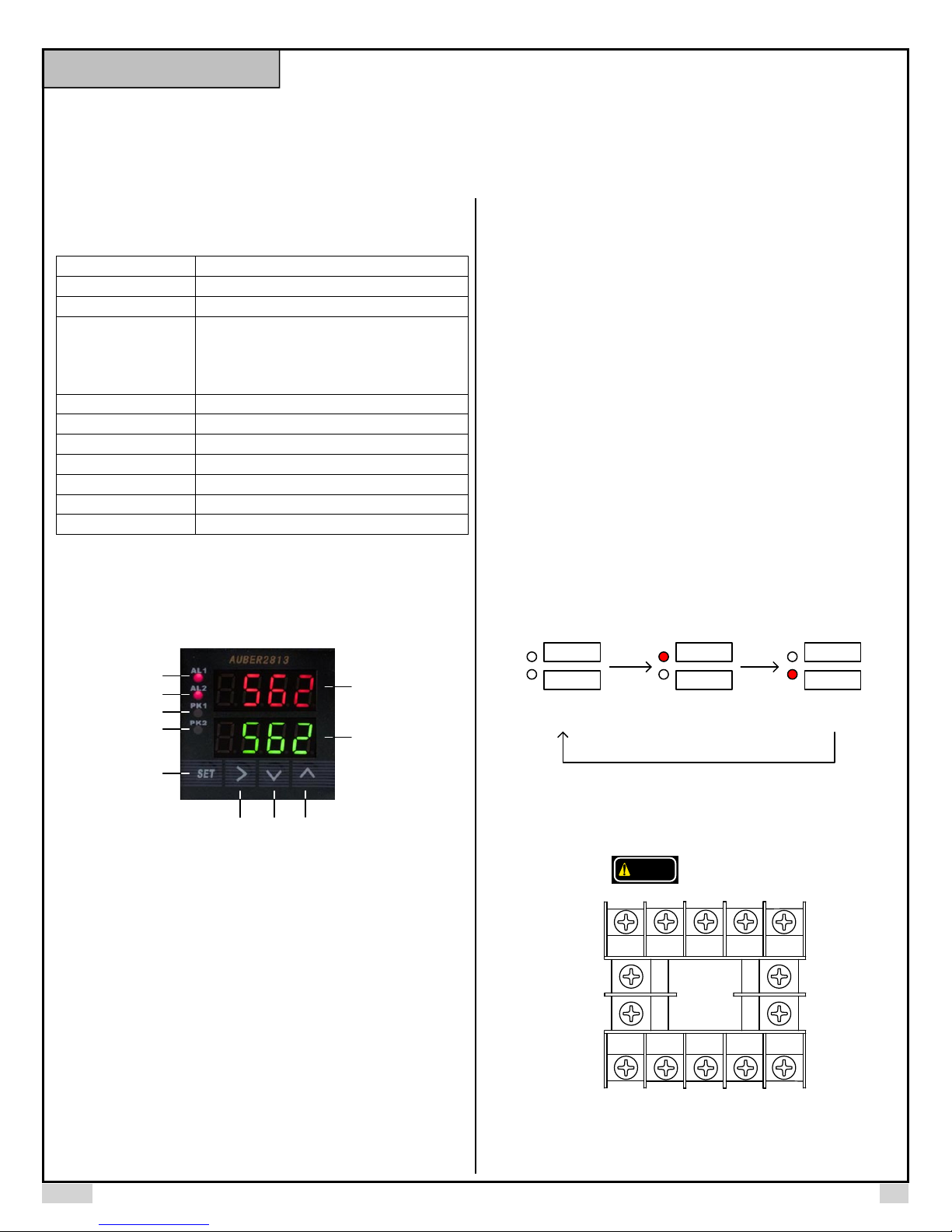
B. Front Panel
①
②
⑨
③
④
⑩
⑤
⑧⑦⑥
Figure 1. Front panel of SYL-2813.
① Alarm1 and relay J1 indicator (red LED)
② Alarm2 and relay J2 indicator (red LED)
③ Maximum value indicator of Channel1 (red LED)
④ Maximum value indicator of Channel2 (red LED)
⑤ SET key
⑥ SHIFT key
⑦ DOWN key
⑧ UP key
⑨ Display1 window (top display)
⑩ Display2 window (bottom display)
1. AL1 (or AL2) on indicates alarm is on and J1 (or J2) relay is pulled in
(closed).
2. PK1 (or PK2) is on when display windows shows the maximum value MA1
of Channel 1 (or the MA2 of Channel 2) and the time MAt1 (or MAt2) when the
peak value was caught.
3. SET key. In Normal Operating Mode, press SET once, enter the code for a
setting mode. Press SET again to enter the setting mode. In Parameter Setting
Mode, press it to select a parameter or to save the value.
4. SHIFT key “>”. In the Parameter Setting Mode, press this key to select the
digit to be changed. In the Normal Operating Mode, press this key to toggle the
displayed variables between Process Values (PV1 and PV2), Maximum Value
of Channel 1 (MA1 and MAt1), and Maximum Value of Channel 2 (MA2 and
MAt2). See the diagram below. Please note that time is expressed in seconds
when it is less than 9999 seconds. Time longer than 9999 seconds will be
displayed as Hours. Minutes (hh.mm).
5. DOWN key “V”. In the Parameter Setting Mode, press it to scroll the
parameter list in a reversed order or decrease the parameter value. In the Peak
Value Checking Mode, press it for 2 seconds to reset the peak values stored in
the memory. In the Normal Operating Mode, press this key to toggle the
display the current readout and value difference if the feature is enabled.
6. UP key “Λ”. In the Parameter Setting Mode, press it to scroll the parameter
list or to increase the parameter value. In the Normal Operating Mode, press
this key to toggle the display brightness between bright and dim. Each time the
key is pressed the display brightness will be changed.
PV1
PV2
Process Values
(PK1 and PK2 are off)
“>” Key
MA1
MAt1
Peak Value of
Channel 1
(PK1 on)
“>” Key
“>” Key
MA2
MAt2
Peak Value
of Channel 2
(PK2 on)
Figure 2. Diagram of how to check Peak Values.
C. Terminal Assignments
DC 12V
14
13
TC1
mA1
mV1
Light
Int.
8910
SYL-2813
2
3
TC2
mV2
+ −
67
P2 (V2)
P1 (V1)
1
Gnd
Figure 3. Terminal assignments of SYL-2813.
COM
5V out
(J1/J2)
12
11
45
RTD1 RTD2
J1 output
(NO)
J2 output
(NO)
2017.01 P1/5
Page 2
AUBER INSTRUMENTS WWW.AUBERINS.COM
C.1 Description of Wiring Terminals (T1 ~ T14)
T1: the circuit ground pole for input signals.
T2: for TC, mA, and mV signals in Channel 1 (use withT1).
T3: for TC, mA, and mV signals in Channel 2 (use withT1)
T4: for RTD signal in Channel 1 (use withT1 and T2).
T5: for RTD signal in Channel 2 (use withT1 and T3).
T6: for the positive side of 12V DC power.
T7: for the negative side of 12V DC power.
T8: for +12V DC illumination signal from headlight (use with T7).
T9: a 5V DC power for pressure sensor (use with T13/T14 and T1).
T10: the common pole for J1 and J2 relay.
T11: output for J2 (normally open) relay (use with T10).
T12: output for J1 (normally open) relay (use with T10).
T13: for pressure sensor in Channel 1 (use with T9 and T1).
T14: for pressure sensor in Channel 2 (use with T9 and T1).
Please see Table 2 for a summary for terminal assignment.
Table 2. Summary of Terminal Assignments.
Terminal Description Channel Use With
T1 Circuit Ground (all input sensors) 1 & 2
T2 TC1, mA1, mV1 1 T1
T3 TC2, mA2, mV2 2 T1
T4 RTD1 1 T1 & T2
T5 RTD2 2 T1 & T3
T6 +12V DC power T7
T7 -12V DC power T6
T8 Headlight signal +12V DC T7
T9 5V DC output for pressure sensor 1 & 2
T10 Common pole for relays 1 & 2
T11 Output for J2 relay T10
T12 Output for J1 relay T10
T13 Pressure sensor 1 (voltage signal) 1 T9 & T1
T14 Pressure sensor 2 (voltage signal) 2 T9 & T1
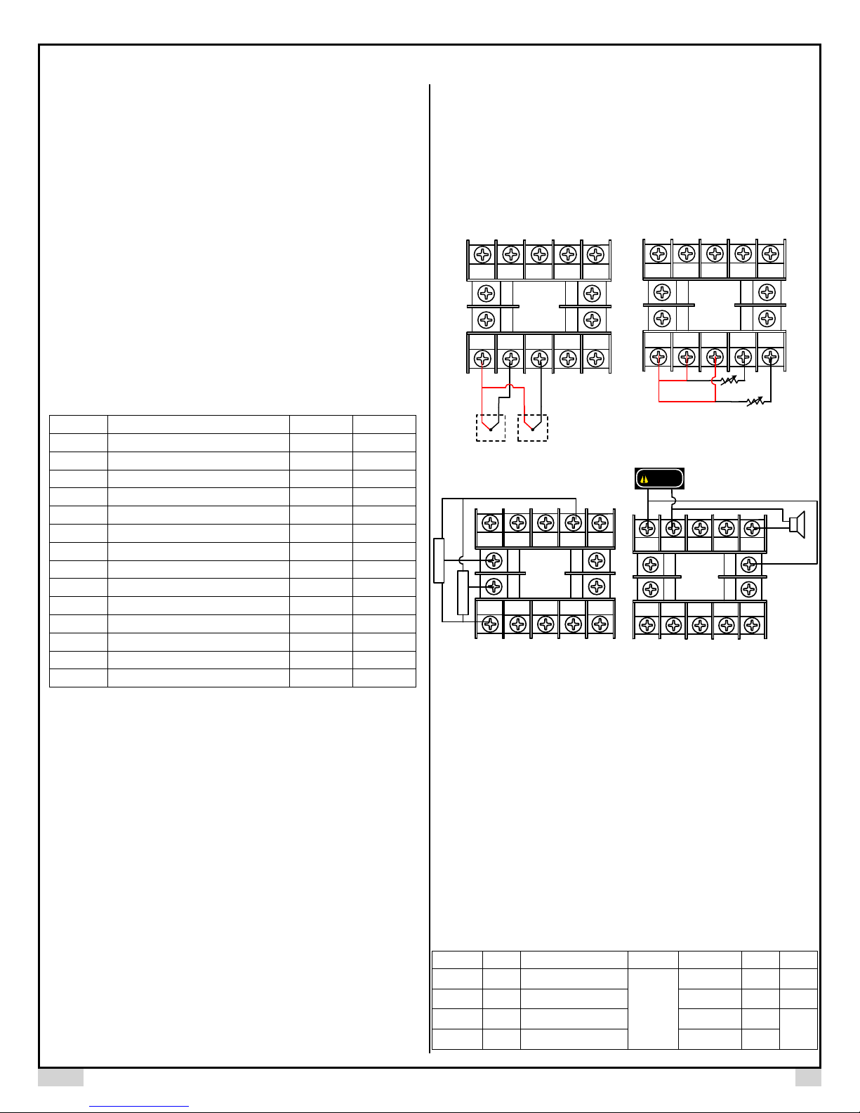
C.2 General Wiring Rules
1. T6 and T7 are 12 VDC power input for the controller.
2. T1-T5, T13, and T14 are for different types of input signals. T1 is the circuit
ground for all input signals.
3. Wiring of Thermocouples (TC). For Channel 1, connect the positive side of
the TC to T2, the negative side to T1. For Channel 2, connect the positive side
of the TC to T3, the negative side to T1. (See Figure 4(a).)
4. Wiring of Resistance Temperature Detectors (RTD). In Channel 1, for a
three wire RTD, connect the two red wires to T1 and T2, connect white wire to
T4; for a two wire RTD, connect the red wire to T2, and connect the white wire
to T4, and short T1 and T2. In Channel 2, for a three wire RTD, connect the
two red wires to T1 and T3, connect white wire to T5; for a two wire RTD,
connect the red wire to T3, and connect the white wire to T5, and short T3 and
T1. (See Figure 4(b).)
5. Wiring of Pressure Sensors. In Channel 1, connect the power source wire of
the sensor to T9, the signal wire of the sensor to T13, and the ground wire of
the sensor to T1. In Channel 2, connect the power source wire of the sensor to
T9, the signal wire of the sensor to T14, and the ground wire of the sensor to
T1. (See Figure 4(c).)
6. Wiring of mV and mA signals. Wiring for these signals are similar to
thermocouple sensors.
7. T8 is for display brightness control. When connecting the illumination signal
(+12 VDC) to it, the brightness with synchronized with headlight. If not
connected, the brightness can still be controlled by UP key “Λ”. Use T8 and T7.
8. Wiring for relay output. J1 and J2 are two normally open relays. T10 is a
common pole for both relays. Use T12 and T10 for J1 relay. Use T11 and T10
for J2 relay. (See Figure 4(d).)
67
14
13
2
1
8910
12
SY L- 28 13
11
45
3
67
1
8910
14
SYL-2813
13
2
3
12
11
45
− + +
Gro und
TC2TC1
RR
R
W
RTD1
R
W
RTD2
(a) (b)
5V power
67
Pressure Sensor 2
Pressure Sensor 1
1
8910
14
SYL-2813
13
2
3
12
11
45
DC 12V
+ −
67
14
13
2
1
Comm on
8910
12
SYL-2813
11
45
3
Buzze r
(controlled by
J1 relay)
Ground
(c) (d)
Figure 4. Wiring diagram for (a) thermocouples, (b) RTDs, (c) pressure sensors, and (d)
relays.
D. Parameter Settings
D.1 Basic Parameters (Press SET key then enter 0089 to enter setting mode)
D.1.a) Basic Parameters
The gauge SYL-2813 has two input channels that can read signals from two
different sensors simultaneously. Each channel can have its own input sensor
type, specified scale range, and input offset. See Table 3 for a list of basic
parameters, description, range, and initial values. A list of valid types of input
sensor is given in Table 4. Please note that all 19 input types are available for
Channel 1, but the last three input types in Table 3, i.e., 0 - 10 mA, 0 - 20 mA,
and 4 - 20 mA, are not available for Channel 2.
Table 3. Basic Parameters.
Symbol Name Description Channel Range Initial Note
Int1
Dot1
Pul1
Puh1
Int1 Input type of Channel 1
dot1 Decimal Point Position 1 0000 ~ 0.000 0 2
PuL1 Scale Low 1 -1999 ~ 9999 1000
PuH1 Scale High 1 -1999 ~ 9999 2000
See Table 3 P100 1
1
3
2017.01 P2/5
Page 3

AUBER INSTRUMENTS WWW.AUBERINS.COM
Psb1
Int2
Dot2
Pul2
Puh2
Psb2
C-F
Filt
End
Note 1. All 19 input types are available to Channel 1. The 375R, 10 mA, 20
mA, and 4 - 20 mA input types are not available to Channel 2.
Note 2. Dot parameter does not work for temperature input sensor
(thermocouple, RTD). Thermocouple will be displayed as integer (XXXX). RTD
will be displayed with 1 decimal place (XXX.X).
Note 3. Only valid for input types that are neither TC nor RTD.
Note 4. Display Value = gauge reading + PSb. Only valid for TC and RTD
signals. To enter negative value, please use shift key to shift to first left digit,
then use UP and DOWN key to scroll to the negative sign.
Note 5. Digital Filtering Coefficient: 0, no filter; 1, weak; 2, medium; 3, strong.
Table 4. Input type options.
(TC: thermocouple. RTD: resistance temperature detector.)
Note: * These sensor types are not available to channel 2.
D.1.b) The Procedure of Setting Basic Parameters (see Figure 5).
To set or view Basic Parameters, press SET key once, the upper window will
display “pass” and the lower window will display “0000”. Change the number to
PSb1 Input Offset 1 -1000 ~ 1000 0 4
Int2 Input type of Channel 2
dot2 Decimal Point Position 2 0000 ~ 0.000 0 2
PuL2 Scale Low 2 -1999 ~ 9999 3000
PuH2 Scale High 2 -1999 ~ 9999 4000
PSb2 Input Offset 2 -1000 ~ 1000 0 4
C-F Temperature Unit
Filt Filter Coefficient 0 ~ 3 0 5
End Exit
Symbol Input Type Gauge Range Resolution Accuracy Impedance
T TC, Type T -200 ~ 400 °C 1 °C (°F) 0.3 % 100 K
R TC, Type R -50 ~ 1600°C 1°C (°F) 0.3 % 100 K
J
Wre TC, WRe3/25 0 ~ 2300°C 1°C (°F) 0.2 % 100 K
B TC, Type B 260 ~ 1800°C 1°C (°F) 0.2 % 100 K
S TC, Type S -50 ~ 1600°C 1°C (°F) 0.3 % 100 K
K TC, Type K -200 ~ 1300°C 1°C (°F) 0.2 % 100 K
E TC, Type E -200 ~ 850°C 1°C (°F) 0.2 % 100 K
P100 RTD, Pt100
Cu50 RTD, Cu50 -50.0 ~ 150.0°C 0.1°C (°F) 0.5 % (0.2 mA)
375R
75mv 75 mV 0.1 % 100 K
30mv
0-5v 0 - 5 V 0.1 % 100 K
1-5v 1 - 5 V 0.1 % 100 K
10v 0 - 10 V 0.1 % 100 K
0-10 0 - 10 mA * 0.3 % 150 K
0-20 0 - 20 mA * 0.2 % 150 K
4-20 4 - 20 mA * 0.2 % 150 K
TC, Type J -200 ~ 1200°C 1°C (°F) 0.3 % 100 K
-199.9 ~
600.0°C
375 Ω, Pressure *
30 mV 0.1 % 100 K
the display
values
can be set to any
range within
(-1999 ~ 9999)
1 & 2
See Table 3 Cu50 1
2
C, F C
0.1°C (°F) 0.2 % (0.2 mA)
0.2 % (0.2 mA)
16 Bit A/D
3
“0089” in the lower window and press SET again to enter the Parameter
Setting Mode. Two parameters from the parameter list will be displayed. The
upper window will flash the first parameter, the lower window will steadily
display the next parameter on the list (see table 3). Use UP or DOWN key to
scroll to the desired parameter (flashing in the upper window) and press SET to
view the value. For numerical values, use SHIFT key to go to any digit that
needs to be changed and use UP or DOWN key to change the value. For letter
values, use UP or DOWN key to select from available values. Then press SET
to save and exit to the parameter list. To exit this mode, use UP or DOWN key
to scroll to “End” (flashing in the upper display window) and press SET. See
Figure 4 for a schematic diagram of how to change Basic Parameters.
Int1
dot1
dot1
PuL1
End
Int1
Basic Parameter
Setting Mode
SET
Int1
0-5v
SET
Normal
Operating Mode
PV1
PV2
Figure 5. Schematic diagram of how to set Basic Parameters.
PAS S
SET SET
0000
enter code
0089
UP key
D.2 Alarm Parameters (Press SET Key and enter 0001 to enter setting mode)
D.2.a) Alarm Parameters and Alarm Relays
Relay J1 and J2 are normally open (NO) relays associated with alarm settings
of Channel 1 and Channel 2 respectively. Each relay has two alarm
parameters AH and AL. The parameter AH (AH1 for Channel 1, or AH2 for
Channel 2) is the relay pull-in temperature, and the parameter AL (AL1 for
Channel 1, or AL2 for Channel 2) is the relay drop-off temperature. The range
for each alarm parameter is shown in Table 5. If AH > AL, relay acts as a high
temperature alarm relay; if AH < AL, relay acts as a low temperature alarm
relay; if AH = AL, the relay/alarm is disabled. Please see Note 6, Figure 7, and
Figure 8 for details.
Table 5. Alarm Parameters.
Symbol Name Description Range Initial Note
AH1 AH1 J1 on -1999 ~ +9999 800
AL1 AL1 J1 off -1999 ~ +9999 900
AH2 AH2 J2 on -1999 ~ +9999 800
AL2 AL2 J2 off -1999 ~ +9999 900
6
Note 6. Relay Action Setting.
For either J1 or J2 relay:
1). When AH = AL, relay is disabled.
2). When AH > AL, relay is set as high limit alarm (see Figure 6).
3). When AH < AL, relay is set as low limit alarm (see Figure 7).
2017.01 P3/5
Page 4

AUBER INSTRUMENTS WWW.AUBERINS.COM
AH1
PV1 PV1
AL1
SV1
R ela y o n R ela y o n
AL1
AH1
SV1
Figure 6. Absolute high alarm on J1. Figure 7. Absolute low alarm on J1.
D.2.b) How to change parameters under code 0001.
The procedure for setting Alarm Parameters is similar to Basic Parameters
showed in Figure 4 except the access code is 0001.
D.3 System Parameters (Press SET then enter 0036 to enter)
Parameters related to peak value recording, display brightness, and input
calculation function are grouped under access code 0036.
D.3.a) Parameter Description
Table 6. List of System Parameters.
Symbol Name Description Range Initial Note
MA1 MA1 Peak Value 1 on/off on
MAt1 MAt1 Timestamp of MA1 on/off off 7
MA2 MA2 Peak Value 2 on/off on
MAt2 MAt2 Timestamp of MA2 on/off off 7
Clr Clr Peak Value Clear on/off off 8
Bt-l bt-L Brightness level -- Low 1 - 2 1 9
Bt-h bt-H Brightness level -- High 3 - 4 4 9
Fun1 fun1 Function 1: Calculate Input
Difference
End End Exit
Note 7. When MA1 (or MA2) is set to “off”, setting for MAt1 (or MAt2) will be
ignored.
Note 8. When Clr is set to “off” (default), the controller will keep all the peak
values even the power is lost. When Clr is set to “on”, current peak value will
be reset when you reboot this gauge.
Note 9. There are totally 4 brightness levels of the LED display, from 1 to 4, the
higher the number, the brighter the display. The brightness of the LED display
can be switched between Low (dimmed) and High. The parameter “bt-L”
defines the brightness level of the dimmed display, while the parameter “bt-H”
defines the brightness level of the bright display. Supply a 12 VDC signal at
terminal 8 or press the UP key (“∧”) on the key pad will switch the display level
between bright and dimmed display. Please note, you need to switch the
brightness level once (press the UP key) to activate the new brightness level
settings.
Note 10. This parameter defines whether to enable Function 1, which
calculates the arithmetic difference between the readings of two input channels
(i.e., Channel 1 - Channel 2). By default, this parameter is set to “off”. When
“Fun1” is set to “on”, user can view the calculation result in the lower window
by pressing the DOWN arrow key. Press the DOWN key again will switch the
lower display back to the probe reading. Please see section D.3.g in this
manual for details.
on/off off 10
D.3.b) How to Change the Parameters Under Code 0036.
The procedure of setting Peak Value Parameters is similar to the Basic
Parameters showed in Figure 4 except the access code is 0036.
D.3.c) Check the Peak Value
To check the Peak Value during operation mode, use the SHIFT key “>”. Press
“>” once, the PK1 indicator will be on, MA1 and MAt1 will be displayed in the
upper and lower window respectively. Press “>” key again, the PK2 indicator
will be on, MA2 and MAt2 will be displayed in the upper and lower window
respectively; press “>” again to exit this mode and return to the Normal
Operating Mode.
D.3.d) Reset the Peak Value
Current Peak Values will be automatically reset when this gauge is powered
off. To reset them manually, change display to show MA1, MAt1, MA2, and
MAt2. Then, press and hold DOWN key “V” for 3 seconds. The display will
show “----“ , indicating the memory (for all four peak parameters) is cleared.
The gauge will start to catch the new peak after 2 seconds.
D.3.e) Timer of Peak Values
If MAt1 (or MAt2) is set to “on” a timestamp will be saved when peak value
MA1 (or MA2) is recorded. The timer starts counting time after the gauge is
powered on. The timestamp will be displayed in seconds if it is less than 9999
seconds; if the timestamp is longer than 9999 seconds, it will be displayed as
Hours.Minutes (HH.MM).
D.3.f) Change the Brightness of the Display
The bt-L value decides the brightness level of the dim display, available levels
are 1 and 2. The bt-H value decides the brightness level of the bright display,
available values are 3 and 4. There are totally 4 brightness levels of the LED
display, from 1 to 4, the higher the number, the brighter the display. Supply a
12 Vdc signal at terminal 8 or press the UP key (“∧”) on the key pad will switch
the display level between bright and dimmed display.
Note: The gauge needs about 1 - 2 seconds to powering up. Supplying a
+12 VDC signal to terminal 8 during the powering up period won’t switch the
display to dim level; on the contrary, remove the 12 VDC signal from terminal 8
will dim the display.
D.3.g) Show Input Difference
This feature calculates the arithmetic difference between the displayed
readings of two input channels, and shows the difference on the channel 2
window:
Input Difference = Channel 1 Reading - Channel 2 Reading.
By default, this feature is turned off (Fun1 = off). When set Fun1 = on, this
function is enabled. User can check the calculated result in the lower window
by pressing the DOWN arrow key. Press the DOWN key again will switch the
lower display back to the probe reading. For instance, if Channel 1 is
connected to a RTD probe and it shows 200°F, and Channel 2 is connected to
another RTD probe that reads 80°F. When press the DOWN arrow key, the
lower window will show 120.
Please note that the gauge will calculates the arithmetic difference between
Channel 1 and Channel 2 readings despite that these two readings can have
2017.01 P4/5
Page 5

AUBER INSTRUMENTS WWW.AUBERINS.COM
different units. For example, if Channel 1 is reading an EGT probe showing
1000°F, while the Channel 2 is reading a pressure sender showing 50 PSI,
when you press the DOWN key, the lower window will show 950.
E. Application Examples
E.1 Measuring Exhaust Gas Temperature (EGT) and Boost Pressure.
The SYL-2813 gauge has two input channels and it can read two different
types of signal simultaneously. The wiring diagram of connecting an EGT
sensor and a MAP sensor to SYL-2813 is shown in Figure 8. The steps for
setting up the gauge for this application is also given in this section.
E.1.a) Wire the EGT sensor (K type thermocouple in this example) and the
MAP sensor (AUBER-303) as shown the Figure 7, where the EGT sensor is
connected to channel 1 and MAP sensor is connected to channel 2.
E.1.b) Press SET, change the code to 0089 to enter the Basic Parameter
Setting mode. Set Int1 to “k” and Int2 to “0-5v”.
E.1.c) To display the pressure in Bar with 0.01 bar resolution, set the decimal
point dot2 = 2 (this step needs to be done before set PuL2 and PuH2). Set the
PuL2 = -0.38 and PuH2 = 03.38. (Please see the installation guide for AUBER303 from the product page on our website).
E.1.d) To display the pressure in PSI with 0.1 PSI resolution, set the decimal
point dot2 = 1. Set PuL2 = -05.4 and PuH2 = 048.9.
DC 12V
display will show reading from probe #1, and the lower display will show
reading from probe #2. To check the difference, press the DOWN “V” key
shortly, and the lower display will show the difference. Press the DOWN key
again, lower display will be switched back to reading from probe #2.
DC 12V
−
+
67
14
13
1
−
+
EGT sensor
(K Type Thermocouple)
Figure 9. SYL-2813 wiring example of an EGT sensor in Channel 1 and an Oil/Water
Temperature Sensor in Channel 2.
8910
SY L-281 3
2
3
Oil/Wat er Tem peratu re
12
11
45
sensor (RTD)
12 VDC
buzzer
(op tional)
5V
power
MAP sensor
Signa l
Ground
Figure 8. SYL-2813 wiring example of EGT sensor in Channel 1 and MAP sensor in
Channel 2.
−
+
67
14
SYL-2813
13
2
1
+
−
EGT sensor
(K Type Thermoc ouple)
8910
12
11
45
3
12 VDC
buzzer
(op tional)
E.2 Measuring Exhaust Gas Temperature (EGT) and Oil Temperature.
To measure temperatures with one thermocouple sensor and one RTD sensor,
you can wire the sensors to SYL-2813 gauge as the diagram in Figure 9. In this
diagram, the thermocouple is connected to the Channel 1, and the RTD sensor
is connected to the Channel 2. You will need to change the input types and
other parameters for Channel 1 and 2 accordingly.
E.3 Read Temperature Difference Between Two Probes.
In this example, a type K thermocouple is wired to channel 1, and a PT100
probe is wired to channel 2 (see Figure 10 for wiring). To set up the gauge to
show the temperature difference in the lower window, please use access code
0036, and then set parameter Fun1 = on. In normal operation mode, the top
Figure 10. Wiring diagram of connecting two temperature probes to SYL-2813A
gauge and show the temperature difference between two probes.
(End)
Auber Instruments
5755 North Point Parkway, Suite 99
Alpharetta, GA 30022, USA
www.auberins.com
E-mail: info@auberins.com Tel: 770-569-8420
No part of this manual shall be copied, reproduced, or transmitted in any way without the prior, written
Copyright 2007-2019. Auber Instruments All Rights Reserved.
consent of Auber Instruments. Auber Instruments retains the exclusive rights to all information
included in this document.
2017.01 P5/5
 Loading...