

Page 1
AUBER INSTRUMENTS WWW.AUBERINS.COM
2019.07 P1/7
SYL-2615 Wi-Fi BBQ Controller
Version 1.3 (July, 2019)
Caution
• This controller is intended to control equipment under normal operating
conditions. If failure or malfunction of the controller may lead to abnormal
operating conditions that may result in personal injury or damage to the
equipment or other property, devices (limit or safety controls) or systems
(alarm or supervisory) intended to warn of or protect against failure or
malfunction of the controller must be incorporated into and maintained as
part of the control system.
• This controller carries a one (1) year warranty. This warranty is limited to
the controller only.
1. Product Overview
This controller SYL-2615 is a Wi-Fi enabled dual-probe PID controller
designed for charcoal smokers and grills. It not only monitors the pit and food
temperature, it also controls the temperature. It will regulate a 12 VDC blower
to stabilize the temperature in the charcoal smoker by either PWM or fan
speed. It has built-in solid state relay that can drive a 12 VDC operated blower
up to 60 CFM. It has a built-in buzzer that can be set for both low limit and
high limit alarm.
Two RTD temperature probes are available on this controller. Probe 1 is for
measuring the smoker temperature (Pit Temp). The controller regulates the
power output of the controller based on the temperature difference between
Probe 1 and the Pit set temperature. Probe 2 is for measuring the food
temperature (Food Temp), which can be used to decide whether it is the time
to change the set temperature for the pit, or to decide whether is food is done.
This controller can be set to single-step mode, or multi-step mode. In the
single-step mode, the user only needs to set the target pit temperature; timer
setting is not needed. In the multi-step mode, the user can program up to 3
cooking steps. Each cooking step can either end by time or end by food
temperature. When the user is cooking food of small size of which the cooking
time is known, or only to add the smoke flavor to the food, the user can simply
use the timer to end a step. When the user is cooking food of large size of
which the cooking time is unknown, it is better to set a target food temperature
to end the step.
SYL-2615 has a build-in Wi-Fi module which allows its user to monitor the
temperature and control the device from a smart phone or a tablet. Once the
connection is set up, the user can access the data and change parameter
settings even the user is miles away from the device. For details, please check
the supplementary manual for details regarding the Wi-Fi function.
2. Specifications
AC adaptor: 100 V ~ 240 V, 50 / 60 Hz input. 12 VDC, 1 Amp output.
Power consumption: < 0.9 W (without blower).
LCD display: Black on white with backlight.
Output for fan: 12 VDC, 1 Amp *.
Control mode: PID-PWM, PID-Fan Speed, Manual.
Alarm: High/low alarms for pit temperature. High alarm for food temperature.
Sampling rate: 2 samples/second.
Accuracy: 0.2% full scale.
Display range: -99°F ~ 930° F, or -99°C ~ 500°C.
Sensor type: PT1000 RTD, -99°F ~ 660° F (-99°C ~ 350°C).
Wi-Fi module Wireless standards: IEEE 802.11 b/g/n
Security protocols: 64/128 - bit WEP, WEPA, WPA2, TKIP, AES.
Dimensions: 4.4” x 3.3” x 1.3" (113 x 83 x 33 mm).
Note * Up to 3 Amp can be supplied if more powerful power adapter is used.
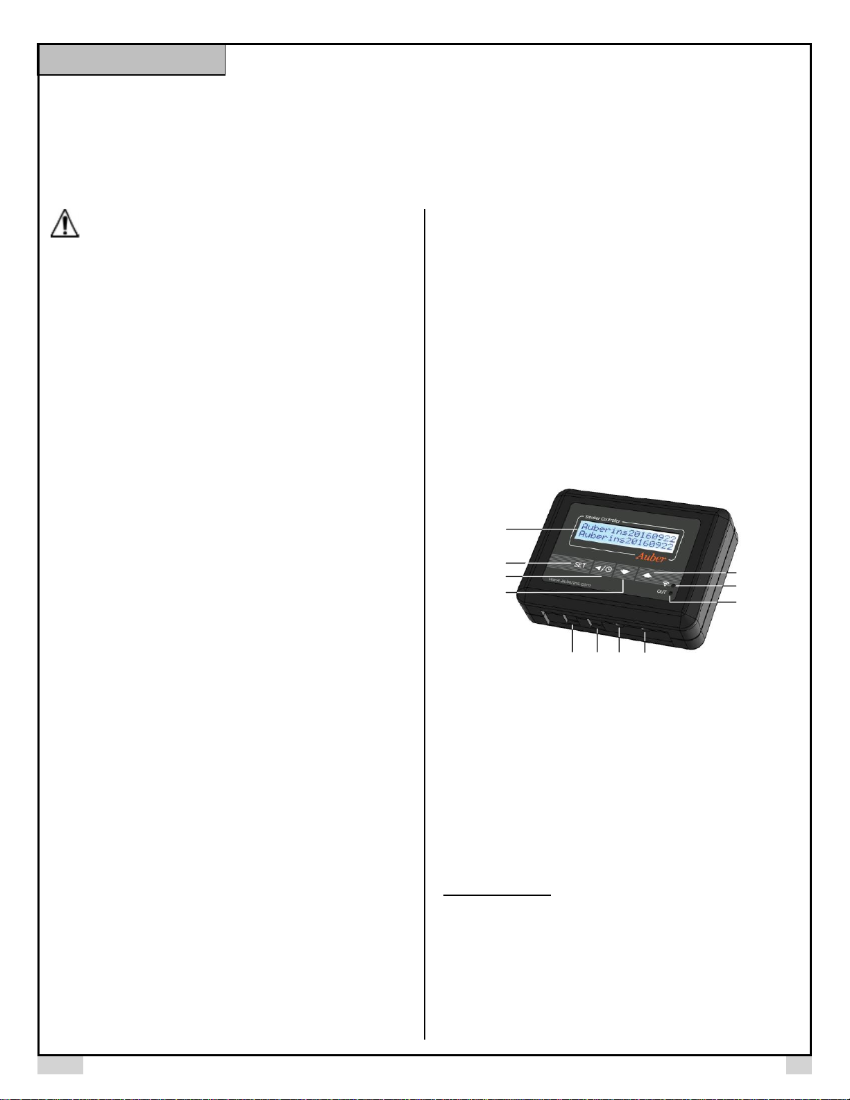
3. Front Panel and Connections
Figure 1. Controller SYL-2615.
① LCD display.
② Set key. Press momentarily to enter the cooking step settings. Press and
hold about 2 seconds to enter the parameter settings.
③ Timer/Back key. Press it in main display will show the cook time. Press it
in the parameter setting mode will return back to the upper level menu. When
open lid detection stops the blower, press it will resume the blower normal
function.
④ Down key. Decrease value, scroll down the menu, mute the buzzer.
⑤ Up key. Increase value, scroll up the menu, or mute the buzzer.
New feature for Up key: Press and hold UP key for 3s to pause the fan output
temporarily. Press the UP key again momentarily to resume the previous fan
output. This feature is available for firmware version 1.9 or newer.
⑥ Wi-Fi status indicator. Solid ON: the controller is connected to the internet.
Quick flashing: Wi-Fi module ready for configuration. Slow blinking: Wi-Fi
module is initializing its connection to the router. Off: no Wi-Fi connection.
⑦ OUT indicator. It indicates the current output status. Its flashing rate only
represents the output level and it is not synchronized with the actual output
status.
⑧ Probe 1 input for Pit temperature.
Page 2

AUBER INSTRUMENTS WWW.AUBERINS.COM
2019.07 P2/7
⑨ Probe 2 input for Food temperature.
⑩ Power output for fan control.
⑪ Power input for controller (12 VDC).
4. LCD Display Modes
Time:
0:15
|
Press
Momentarily
Pit: 73 Set:225
Food:71 Out:99
Normal Display
>Step: 1 Pit: 225
Back
SET
Press
Momentarily
> Control config
System config
Time Checking
Cooking Profile Parameter Settings
SET
Press
&
Hold
Time: 0:02/ 9:00
Tot: 0:10 Step: 2
OR
Time Checking
Figure 2. Switching between different display modes.
4.1 Normal Display Mode
Pit: 73 Set:225
Food:71 Out:99
Figure 3. Information displayed on the LCD in the normal operating mode.
① Pit temperature
② Food temperature
③ Set value for pit temperature
④ Output power (percentage)
4.2 Time-Checking Mode
Time:
0:15
Pit: 73 Set:225
Food:71 Out:99
|
Press
Time: 0:02/ 9:00
Tot: 0:10 Step: 2
Pit: 73 Set:225
Food:71 Out:99
|
Press
Figure 4. Using Timer/Back key to check cooking time in single-step mode
(left) and in multi-step mode (right).
Press the Timer/Back key can tell you the current timer and step information.
In single step mode, press timer key will show the total running time after your
powered this controller up this time. In multi-step mode, pressing timer key will
display more information, including the elapsed time for current step and total
time for current step (first line); total elapsed time and current step number
(second line).
This key has two more functions: a) Press it in the parameter setting mode will
return back to the upper level menu. This provide a short cut to exit the current
menu. b) Cancel the open lid detection. For details, please see Note 8 in
section 6.2.2.
4.3 Cooking Profile Programming Mode
The controller’s cooking profile can be either set to single-step mode (default)
or set to multi-step mode. In the single-step mode, the controller will try to
maintain the pit temperature at the set value of Step 1 as long as the controller
is on. In the multi-step mode, up to 3 steps can be programmed. Each step
has its own set temperature for pit probe, and its step-ending criterion. A
cooking step can either end by timer or by food temperature. For details,
please check section 6.1.
4.4 Parameter Setting Mode
> Control config
System config
Pit: 73 Set:225
Food:71 Out:99
SET
Press and hold
Figure 5. Access the menu of parameters using SET key.
5. Getting Started
Power on the controller by plugging the barrel connector from the 12 VDC
adapter to the power input port ⑪. Connect the pit probe (probe 1) to socket
⑧, food probe (probe 2) to socket ⑨. Configure the Wi-Fi connection from
your phone using AuberSmart app*. After you have set up the controller and
started fire in your smoker or grill, mount the blower to the smoker/grill, then
plug the blower connector to the fan output port ⑩.
Note *: Please check the supplementary manual for Wi-Fi configuration and
how to use the AuberSmart app.
6. Operation
All cooking profile settings and control parameters can be accessed both from
the device and from the AuberSmart app.
6.1 Set the Cooking Profile
The controller’s cooking profile can be either set to single-step mode (default)
or set to multi-step mode. In the single-step mode, the controller will try to
maintain the pit temperature at the set value of Step 1 as long as the controller
is on. In the multi-step mode, up to 3 steps can be programmed. Each step
has its own set temperature for pit probe, and its step-ending criterion. A
cooking step can either end by timer or by food temperature. To switch
between single-step mode and multi-step mode, please check section 6.1.3.
6.1.1 Single-Step Mode
In this mode, you can only access and change the target pit temperature of
Step 1 from the device. The controller will try to maintain the smoker
temperature at the set temperature of Step 1 continuously as long as the
controller is powered on. If this controller is powered off and turned back on
again, it will resume operating in this mode. You can still view and change
other settings in Cooking Profile from the app, but they don’t apply to this
mode.
To change the set temperature in single-step mode, press SET key once, it
will show “Step: 1” and the current target pit temperature in the top line. A
curser “>” will be shown on the left indicating which line will be selected. Press
SET key once, the current set temperature should start blinking. Use ▲ and
▼ keys to change the set temperature. When finished, press the SET again
to confirm the change. That number will stop blinking. Press the Timer/Back
key to exit the menu. Or use ▲ or ▼ key to scroll to “Back” and then press
SET key to exit. The display will return to the normal display mode if no key is
pressed in 14 seconds.
Page 3

AUBER INSTRUMENTS WWW.AUBERINS.COM
2019.07 P3/7
>Step: 1 Pit: 225
Back
>Back
Step: 1 Pit: 225
V
SET
Pit: 73 Set:225
Food:71 Out:99
SET
Press
Press
Press
SET
Press
>Step: 1 Pit: 225
Back
^
v
Use Up and Down keys to
adjust set pit temp. Press
SET key to confirm.
Figure 6. Change the set temperature in single-step mode.
6.1.2 Multi-Step Mode
A total of 3 steps can be programmed on this controller. Each program step
comprises a target temperature of pit (shown as “Pit: XXX”) and an ending
criterion setting “X-End”, where “X” is the step number. For example, “1-End”
means the ending criterion of Step 1. The “ending criterion” is a new concept
to people who never used our controller for electric smokers. It determines
how does a cooking step is considered finished. Two options are available:
time and food temperature. If you want Step X to end after a pre-set time
period, set “X-End” to “Time”; if you want Step X to end when food
temperature reaches a pre-set value, set “X-End” to “Fd Temp”.
After you set “X-End” to “Time”, you will need to set “X-Time”. Here, “X-Time”
is defined as the time duration (in hh:mm format) of the current step. The timer
will start counting even if the pit temperature has not yet reached the target pit
temperature. So, please make sure that the step time is long enough. If the
step time is too short, the controller may continue to the next step no matter
what the actually pit temperature is. If you set “X-End” to “X-Fd Temp”, you
will need to set “X-Fd Temp” to the desired food temperature (Probe 2).
Timer or Target Food Temp.
1-Time : 1:30
1-Fd Temp : 170
Ending Criterion
1-End : Time
1-End : Fd Temp
Step : 1 Pit: 225
Step Number and
Target Pit Temp .
Figure 7. For each cooking step, set the target pit temperature, ending
criterion, and timer or target food temperature.
From the AuberSmart app, you can still view and change both time and food
temperature of each step, but only one setting is relevant to the current
cooking step depending on the the X-End setting.
If “X-End” of a certain step is set to “Fd Temp” while the food probe is not
plugged in, this step will never end. Pit probe should always be plugged in
otherwise controller will stop sending power to the fan.
Cooking Profile Example 1
Step
Pit
X-End
(Ending)
X-Time
(Timer)
X-Fd
(Food)
1
275
Food temp
N/A
170 2 225
Time
6:00
N/A
3
160
Time
0:00
N/A
In this example, a user set the pit temperature of Step 1 to 275° F, which
is higher than normal smoking temperature, to speed up the “low and
slow” cooking without compromising the moisture. Step 1 will end when
the food temperature reaches 170° F. In Step 2, pit temperature will be
lowered to 225° F and stay there for 6 hours. After that, the program
ends because the Step 3 is set to end by time and the timer is set to
“0:00”. The controller will stop its output when Step 2 is done, it will give
beeping sound until the buzzer is muted or the power input has been
reset.
Cooking Profile Example 2
Step
Pit
X-End
(Ending)
X-Time
(Timer)
X-Fd
(Food)
1
200
time
1:30
N/A 2 225
Time
5:00
N/A
3
225
Time
0:00
N/A
In this program, the pit temperature of Step 1 is set at 200° F for 1 hour
30 minutes. Then, the pit temperature will be raised to 225°F in Step 2
for 5 hours. Step 3 will be skipped because its timer is set to 0:00. The
entire cooking program ends when the Step 2 is finished.
A flow chart of how to enter the cooking profile described in the Example 1 is
shown in Figure 8. To start program the cooking profile, press SET key shortly
to enter the Cooking Profile Programming mode. The top line in the display
shows the step number “Step: 1” and the current target of pit temperature “Pit:
225”. To enter or edit the profile:
1) Use ▲ or ▼ key to move the cursor “>” to the parameter you want to edit.
2) Press SET key, the value to be edited should start blinking.
3) Use ▲ or ▼ arrow key to edit the value.
4) Then press SET key again to save the change. That parameter value will
stop blinking.
5) Use ▲ or ▼ key to go another parameter, repeat the previous operations
till you have finished entering the cooking profile.
The temperature setting will not be saved if SET is not pressed. After
programming the necessary steps for cooking, you can finish programming by
pressing the Time/Back key to exit the menu. Or, you can use ▲ or ▼ key to
go to “Back”, and press SET key to exit. The display can also return to the
normal display mode if no key is pressed in about 15 seconds.
6.1.3 Switch between single-step mode and multi-step mode
To switch between single-step mode and multi-step mode, go to Parameter
Setting mode by holding the SET key, and then go to “System Config” menu,
find parameter “PRG”, then change it to “ON” (for multi-step mode) or “OFF”
(for single-step mode). By default, the controller is set to single-step mode.
Please see the flow chart in Figure 9 for how to access this parameter from
the controller.
Page 4

AUBER INSTRUMENTS WWW.AUBERINS.COM
2019.07 P4/7
Pit: 73 Set:225
Food:71 Out:99
>Step: 1 Pit: 225
1-End: Fd Temp
>1-End: Fd Temp
1-Fd Temp: 170
> 1-Fd Temp: 170
Step: 2 Pit: 225
>Step: 2 Pit: 225
2-End: Time
>2-End: Time
2-Time: 6:00
>2-Time: 6:00
Step 3: Pit: 160
SET
>Step: 1 Pit: 225
>Step: 1 Pit: 275
1-End: Fd Temp
>1-End: Time
1-Fd Temp: 170
1-Fd Temp: 175
>Step: 2 Pit: 225
>Step: 2 Pit: 230
>2-End: Fd Temp
>2-Time: 6:00
>2-End: Time
>Step 3: Pit: 160
3-End: Time
>3-End: Time
3-Time: 0:00
> 3-Time: 0:00
Back
>Step 3: Pit: 160
>Step 3: Pit: 165
>3-End: Time
> 3-Time: 0:00
>2-Time: 6:10
>3-End: Fd Temp
> 3-Time: 0:10
> Back
Step: 1 Pit: 275
SET
SET
SET
SET
SET
SET
SET
SET
SET
/
/
/
/
/
/
/
/
/
SET
SET
SET
SET
SET
SET
SET
SET
SET
SET
Figure 8. How to enter a cooking profile on SYL-2615 controller. The program
shown in Example 1 is used in this flow chart as a demo.
6.2 Set Parameters
To access the parameters, press and hold SET key for about 2 seconds.
Parameters are divided into two groups: “Control Config” and “System
Config”.
6.2.1 Control Configurations
Parameters related control configurations during the smoking process are
listed under “Control Config” menu. Details of each parameters are listed in
Table 2. The flow chart in Figure 9 shows the operations of accessing and
adjusting the parameters in “Control Config”.
Table 2. Parameters in Control Config menu.
Name
Description
Range
Initial
Note
AH (Pit)
Pit High Alarm
0 ~ 999
80 1 AL (Pit)
Pit Low Alarm
0 ~ 999
0 2 AH (Food)
Food High Alarm
0 ~ 999
350
3
P
Proportional
Constant
1 ~ 999
60
4
I
Integral Time
0 ~ 9999
1200
5
D
Derivative Time
0 ~ 999
60 6 T
Control Cycle Time
2 ~ 200
15 7 OL Switch
Open-Lid Detection
ON, OFF
ON
8
Save
Save PID Settings
(Back), BGE,
WSM22,
WSM18,
4,5,6
Back 9 Recall
Recall PID Settings
(Back), BGE,
WSM22,
WSM18,
4,5,6
Back
9
Back
Back to main
menu
> Control config
System config
> AH(Pit): 350
AL(Pit): 0
> AL(Pit): 0
AH(Food): 350
> Back
AH(Pit): 250
SET
SET
> AH(Pit): 350
> AH(Pit): 250
SET
/
SET
> AL(Pit): 0
> AL(Pit): 180
SET
SET
/
Figure 9. Access the parameters in Control Config menu.
Note 1. AH (Pit): This is the high temperature alarm for pit temperature
(Probe 1). When pit probe reading is higher than AH (Pit) value, the buzzer
on the controller will go off and the LCD display will flash between the normal
display and the alarm display showing in Figure 10. The alarm has 1°
hysteresis. The user can mute the buzzer by pressing either the Up key or
the Down key. Temperature must move out of the hysteresis zone to activate
the alarm again. For example, if AH (Pit) is set to 290°F, the buzzer will go
off when Probe 1 reads higher than 291° F, and the buzzer will stop when
Probe 1 reads lower than 289° F. To disable AH (Pit) alarm, you can set it to
a large number, such as 750° F.
Pit
High Alarm
Figure 10. The LCD display when AH (Pit) is triggered.
Note 2. AL (Pit): This is the low temperature alarm for pit temperature
probe (Probe 1). When pit probe reading is lower than AL (Pit) value, the
buzzer on the controller will go off and the LCD display will flash between
the normal display and the alarm display showing in Figure 11. The
alarm has 1° hysteresis. The user can mute the buzzer by pressing
either the Up key or the Down key. Temperature must move out of the
hysteresis zone to activate the alarm again. For example, if AL (Pit) is
set to 180° F. The buzzer will go off when pit temperature drop to 179° F;
it will stop when temperature rise above 181° F. The AL (Pit) alarm is
suppressed when the controller is just powered up. It will be activated
when the pit temperature has reached the target pit temperature. To
Page 5

AUBER INSTRUMENTS WWW.AUBERINS.COM
2019.07 P5/7
disable the AL (Pit) alarm, you can set it to a small number, such as 0°F
(default).
Pit
Low Alarm
Figure 11. The LCD display when AL (Pit) is triggered.
Note 3. AH (Food): This is the high temperature alarm for the food probe
(Probe 2). When food probe reading is higher than AH (Food) value, the
buzzer on the controller will go off and the LCD display will flash between the
normal display and the alarm display showing in Figure 12. The alarm has 1°
hysteresis. The user can mute the buzzer by pressing either the Up key or
the Down key. For example, if AH (Food) is set to 130° F, the buzzer will go
off when Probe 2 reads 131° F, and the buzzer will stop when Probe 2 reads
129°F or lower. To disable AH (Food) alarm, you can set it to a large
number, such as 999° F.
When smoking multiple pieces of meat of different sizes or thickness, you
can put the probe in the thinnest piece first. Set the AH (Food) alarm to the
temperature when meat is ready. It will let you know when it is done. Then,
you can move the probe to the second thinnest pieces and so on. To use this
feature, you can set the ending criterion to time. If you prefer to set the
ending criterion to food temperature, then the Food Temp should be set to
higher than the AH (Food).
Food
High Alarm
Figure 12. The LCD display when AH (Food) is triggered.
Note 4. P: Proportional Constant. The unit is 1 degree. This parameter control
the output of the controller based on the difference between the measured and
set temperature. Larger the P number means the weaker the action (lower
gain). If P = 7, the proportional band is 7 degree. When the sensor
temperature is 7 degrees below the proportional band (10 degrees below the
setting), the controller will have 100% output. When the temperature is 5
degree below the set point, the output is 71%. When the temperature is equal
to the setting, the controller will have 0% output (assuming integral and
derivative functions are turned off). This constant also affects both integral and
derivative action. Smaller P values will make the both integral and derivative
action stronger. Please note the value of the P is temperature unit sensitive. If
you found an optimized P value when operating the controller in Fahrenheit,
you need to divide the P by 1.8 when changing the temperature unit to
Celsius.
Note 5. I: Integral Time. The unit is in seconds. This parameter controls the
output of controller based on the difference between the measured and set
temperature integrated with time. For example, if I = 1000, it means if the
temperature difference between the pit temperature and set temperature stays
constant, the output will be doubled after 1000 seconds. Integral action is
used to eliminate temperature offset. Larger number means slower action.
Note 6. d: Derivative Time. The unit is in seconds. Derivative action
contributes the output power based on the rate of temperature change.
Derivative action can be used to minimize the temperature overshoot by
responding its rate of change. The larger the number is, the stronger the
action will be. For example, when the door of oven is opened, the temperature
will drop at very high rate. The derivative action changes the controller output
based on the rate of change rather than the net amount of change. This will
allow the controller to act sooner. It will turn the heater to full power before the
temperature drops too much.
Note 7. T: Control Cycle Time. The unit is second. This unit determines how
long for the controller to calculate each action. It is only meaningful in the
PWM mode. e.g. if T is set to 15 seconds, when controller decide the output
should be 10%, it will turn on the heater 1.5 second for every 15 seconds. This
parameter is set to 15 seconds by default.
Note 8. OL Switch: Open-Lid Detection Switch. This parameter works as an
on/off switch to enable or disable the Open-Lid Detection function. When OL
Switch is set to “on”, the Open-Lid Detection function is enabled; otherwise,
disabled.
When the lid or dome of a smoker is opened during smoking, the pit
temperature will drop quickly. The derivative function (d) of the PID controller
will force the blower to run, probably at the maximum speed, in order to stop
the trend of temperature-dropping. This action would blow up ashes, blow the
flame stronger, and cause a big temperature overshot after the lid is closed.
The open-lid detection function is designed to prevent these problems.
When the smoker’s lid or dome is opened, this function will detect the sudden
temperature drop and stops the blower. After the lid is closed and the pit
temperature is recovered by the residual heat stored in the smoker, the blower
will resume running. However, after 7 minutes, if the temperature still hasn’t
been recovered yet, the controller will resume sending its output to the blower.
This open-lid detection function is inactive when you starting the fire at the
beginning. It will be activated after the pit temperature less than 5 degree
lower than the set temperature. Sometimes the open-lid detection might be
triggered accidently by a temperature drop not related to lid-opening during
smoking. In that case, you can cancel this activation by pressing the
Time/Back key on the controller, or tap the “X” (Cancel) symbol appeared near
the “Open-Lid Detection” on the SYL-2615 device info page from the
AuberSmart app. In situations where the open-lid detection is activated by
actual lid-opening action, we recommend you not to cancel this function to
avoid getting a pit temperature overshot. The controller can take care of this
issue and minimize the disturbance. But if you are cooking at a higher
temperature range (> 300° F), the pit temperature many not be able to recover
by itself. In this case, cancel the activation.
If you want to manually pause the fan output temporarily, you can press and
hold Up key for 3s. To resume the fan output, press Up key again
momentarily. (firmware 1.9 or newer).
Note 9. Save & Recall: This controller allows the user to save and recall up to
6 sets of the P, I, D, and Control Mode settings. The user can tune the settings
for cooking at different conditions (e.g., different smokers/grills, different
ambient temperature, or cooking temperature) and save them for future use.
Three sets of settings for 18.5’’ Big Green Egg, 22.5” Weber Smoky Mountain,
and 18.5” Weber Smoky Mountain has been pre-saved on the controller as
“BGE”, “WSM22”, and “WSM18” respectively. Another 3 sets of settings
named as “4”, “5”, and “6” are available for custom tuned parameter settings.
The names for those sets cannot be changed at this moment. Please see
Table 3 for the name and the values of each group of settings.
Page 6

AUBER INSTRUMENTS WWW.AUBERINS.COM
2019.07 P6/7
To save the tuned the PID parameters and Control Mode, go to “Save”, press
SET key, use ▲ or ▼ key to find the desired group name, then press SET
again to save the settings.
To recall a saved set of PID parameters and Control Mode, go to “Recall”,
press SET key, use ▲ or ▼ key to find the desired group name, then press
SET again to load the settings as the current PID and Control Mode settings.
Table 3. Saved PID Settings.
Group #
Group Name
P I D
Mode 1 BGE
45
1200
75
PID-PWM
2
WSM22
45
1200
75
PID-FS
3
WSM18
45
1400
100
PID-FS 4 4
45
1200
75
PID-FS 5 5
45
1200
75
PID-FS 6 6
45
1200
75
PID-FS
6.2.2 System Configurations
Parameters related device configurations which are not often used during the
smoking process are listed under “System Config” menu. Details of each
parameters are listed in Table 4. The flow chart in Figure 13 shows the
operations of accessing and adjusting the parameters in “System Config”.
Table 4. Parameters in System Config menu.
Name
Description
Range
Initial
Note
PRG
Multi-Step Program
ON, OFF
OFF
10
MODE
Control Mode
Manual,
PID-PWM,
PID-FS
PID-PWM
11
FMRV
Fan Minimum Running
Voltage
3.0 V ~ 11.0 V
4.0
12
OUTH
Output High Limit
0 ~ 100 (%)
100
13
C-F
Temp Unit (° C or °F)
C, F
F
14
PB1
Sensor 1 offset
-99 ~ 100
0
15
PB2
Sensor 2 offset
-99 ~ 100
0
16
PSD
Device Access
Password
100 ~ 999
666
17
Reset
Factory Reset
Yes, No
No
18
Back
> System config
back
> PRG: OFF
MODE: PID-PWM
> MODE: PID-PWM
FMRV: 4
> back
PRG: OFF
SET
SET
> PRG: OFF
> PRG: ON
SET
/
SET
> MODE: PID-PWM
> MODE: PID-FS
SET
SET
/
Figure 13. Access the parameters in System Config menu.
Note 10. PRG: Multi-step program switch. By default, this controller is set to
single-step mode “OFF”. To enable multi-step mode, please change
parameter PRG to “ON”. For details regarding multi-step mode, please check
section 6.1.2
Note 11. MODE: Control mode. This controller has three operating modes:
time-proportional control (PID-PWM), fan-speed control (PID-FS) and manual
control (Manual). For time-proportional control, it will regulate the on/off time
interval of the blower to stabilize the temperature in the charcoal smoker
(same as SYL-1615 or other standard PID controllers). For fan-speed control,
it will employ PID control algorithm to decide the output voltage to adjust fan
speed. For manual mode, user can manually adjust the fan speed (output
voltage).
Note 12. FMRV: Fan minimum running voltage. This parameter is only used
when controller is running under fan-speed control mode. Due to the variation
in the friction of bearings in blowers, the minimum voltage to overcome the
kinetic friction is not the same between different models and when the bearing
getting old. The default FMRV setting is 4.0 V. This setting is fine for all
blowers sold by Auber. Usually you don’t need to change this parameter when
you are using the controller on metal wall smokers (such as WSMs). If the
output graph shows zero but the temperature stays above setting for more
than 20 minutes, the fan might not stop when controller output shows zero.
You can change to manual mode, and set the output to 1%. Reduce the
FMRV until the blower is barely running.
Note 13. OUTH: Output High Limit. The value is in percentage. This
parameter limits the maximum output power that can be sent to fan.
Note 14. C-F: Temperature unit. You can set the display either Celsius (° C) or
Fahrenheit (°F).
Note 15. PB1/PB2: Calibration offset. The parameter is used to make the
input offset to compensate the error produced by sensor. e.g. if the
temperature displays of Pit temperature is 2.0°C in ice water mixture, set PB1
= -2.0 will make the display to shown 0.0 degree. PB1 is for pit temperature
(Probe 1). PB2 is for food temperature (Probe 2).
Note 16. PSD: Device access password. This parameter is used to lock the
access to parameter settings on AuberSmart app.
Note 17. Reset: Factory reset. WARNING! This function will restore all the
parameters (including all the stored PID settings in the memory) back to the
factory default values. This setting does not affect the WiFi configuration.
7. Mount the Controller
The operating environment temperature for the meter is from 0 - 100° F
(or, -20° C ~ 50° C). The meter should be placed away from high heat to
protect the plastic housing and electronics. The case is splash-proof. It is not
water-prof. It cannot be immersed in the water. It should be fine to operate
under light rain for a short time if the controller is mounted in an upright
position. The user can cover the controller by a transparent waterproof case.
Two mounting screws holds with metric M4 thread are available on the back of
the case (Figure 14). The M4 screws should not be screwed into the hold
more than 3/8” or 9 mm, otherwise they will push against the plastic case,
create cracks, or damage the case. Mount the controller to a place that is
Page 7

AUBER INSTRUMENTS WWW.AUBERINS.COM
2019.07 P7/7
away from the heat from the smoker. Avoid exposing the controller under
directly sunshine during hot summer.
Figure 14. Two M4 screw holes on the back of the controller.
8. FAQ
8.1 Probe reading showing “-H-”.
This is the sensor input error message. It appears when the sensor is not
connected, sensor is bad or controller is bad. If you only see -H- error on one
probe, you can swap two probes to the different sockets (for example, plug in
pit probe to meat probe socket, and plug in meat probe to pit probe socket). If
this issue remains on the probe, your probe is bad. If this issue remains on the
controller, your controller is bad. For more details, please contact customer
support.
8.2 What if one step is set to end by food temperature while the food
probe is not plugged in?
If “X-End” of a certain step is set to “Fd Temp” while the food probe is not
plugged in, this step will never end.
(End)
Auber Instruments Inc.
5755 North Point Parkway, Suite 99,
Alpharetta, GA 30022
www.auberins.com
E-mail: info@auberins.com Tel: 770-569-8420
Copyright 2007-2019, Auber Instruments All Rights Reserved.
No part of this manual shall be copied, reproduced, or transmitted in any way without
the prior, written consent of Auber Instruments. Auber Instruments retains the exclusive
rights to all information included in this document.
 Loading...