

Page 1
AUBER INSTRUMENTS WWW.AUBERINS.COM
Instruction Manual
JSL-73B Multi-Event Timer for Beer Brewing
Version 2.1 (May, 2017)
1. Overview
This timer is designed for home brewing when the brewer needs to follow a
recipe that calls for ingredients to be added at different time points during the
wort boiling process. It can help the brewer keep track of time and remind the
brewer to add ingredients at specific time points. The brewer can simply enter
the boiling time of each ingredient specified by a beer recipe, the JSL-73B
timer will automatically convert it to a multi-event timer whose alarm will go off
at the moment when a new ingredient should be added, as well as when the
boiling process is supposed to end. The relay output of the timer should be
connected to an external flashing buzzer which is sold separately.
2. Specifications
Event timer range: 0 minute to 255 minutes.
Number of events: 1 to 9.
Timer accuracy: < 1 s/day.
Power supply: 90 - 260 V AC or DC.
Power consumption: < 2 W.
Relay output: 7 A @ 240 VAC, 10 A @ 120 VAC and 24 VDC (resistive load).
Average relay life: 100,000 times at rated current.
Operating temperature: 0 - 60°C.
Humidity: 0 - 95% RH.
Panel cutout: 44.5 x 44.5 mm.
Outer dimension: 48 x 48 x 78 mm.
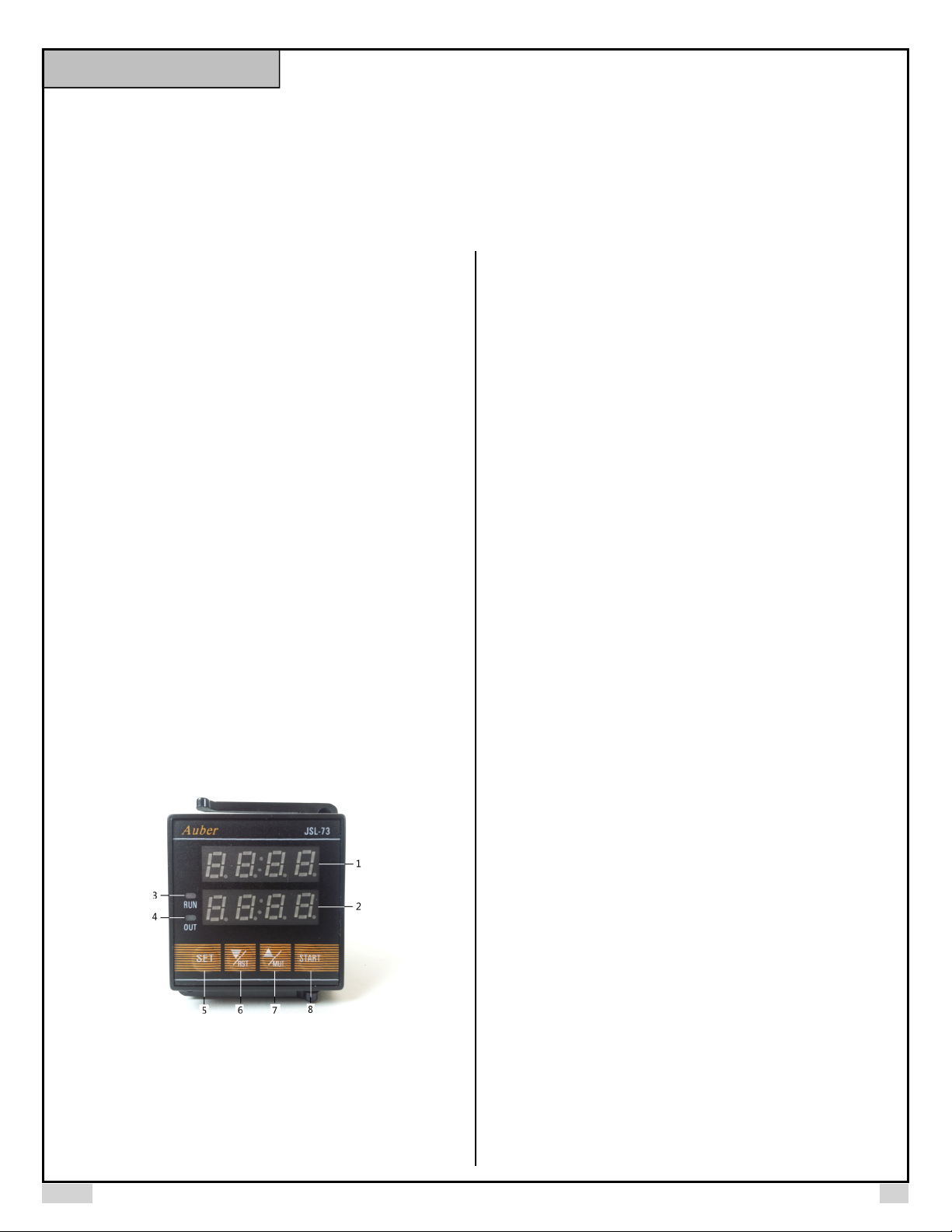
3. Front Panel
the number of the upcoming event (e.g., t2, t3...). When an event time is up, it
will flash the event number (t2, t3, t4, and etc.) until the alarm is turned off. In
programming mode, it shows the name of a parameter. In stopwatch mode (nE
= 1, tdIr = up), it will display the duration of current event.
2). Bottom display window: In normal operation mode, it shows the remaining
time to the end of all events. If the remaining time is longer than 99’59”, the
display will show minutes only. In programming mode, it shows the set value of
the parameter. In stop watch mode, it will display the duration of accumulated
time that has elapsed.
3). RUN indicator: This red indicator should be solid on when the timer is
running; it flashes when the timer is paused; it should be off when the timer is
stopped.
4). OUT indicator: This green indicator turns on when the relay is on (pull-in);
turns off when the relay is off (drop-out). This indicator should be synchronized
with an external flashing buzzer if it was connected to the relay.
5). SET key: Press it momentarily to set event timers t1, t2, t3, and so on;
press and hold it for 1 second to enter the parameter setting mode. In
parameter setting mode, press it momentarily will go to next parameter setting.
This key is disabled when timer is running.
6). V/ RST key: Reset timer or decrease a parameter value. When the timer is
running or is showing “END”, press it to stop the timer and reset the timer. In
the parameter setting mode, press it will decrease the value of a parameter.
Each time you press and release this key, the value will decrease by one unit.
When you press and hold it, the value will continuously decrease; as the
holding time increases, the speed of number decreasing will accelerate.
7). ^ / MUT key: Mute/cancel the relay, or increase a parameter value. When
the timer is running, press this key to allow the coming up event number (t2, t3,
and etc.) to be shown in the top display window. When an event timer is up and
relay is pulled in, press this key once to release the relay. This key only affects
the relay. It does not interrupt the running timer. In stopwatch mode, press it to
restart the count-up timer in the top display window as the second stopwatch.
In the parameter setting mode, press it to increase the value of a parameter.
Each time you press and release, the value will increase by one unit. When
you press and hold it, the value will continuously increase; as the holding time
increases, the speed of number increasing will accelerate.
Figure1. Front panel of JSL-73B timer.
1). Top display window: In normal operation mode, it shows the remaining time
to the next event. If the remaining time is longer than 99'59”, the display will
show minutes only. When ^/MUT key is pressed, it will show
8). START key: Press it to start the timer. When timer is flashing “END”, press
it once to stop the flashing, and get the timer ready for the next run. Press the
START key again will restart the timer. This key is disabled when timer is
running. In stopwatch mode, press it to start and stop the timer.
2017.05 P1/4
Page 2
AUBER INSTRUMENTS WWW.AUBERINS.COM
4. Terminal Assignment
COMRSTMUT
START
Figure 2. Terminal assignment of JSL-73B.
Details:
1
2
3
4
5
6
7
NC
OUT
NO
8
9
90~26 0V
AC
10
The top display window will show the remaining time before the next event, i.e.,
when the next ingredient should be added to the wort. The lower window will
show the remaining time to the end of the wort-boiling process. The alarm relay
will pull in when a new event timer starts or when all events end.
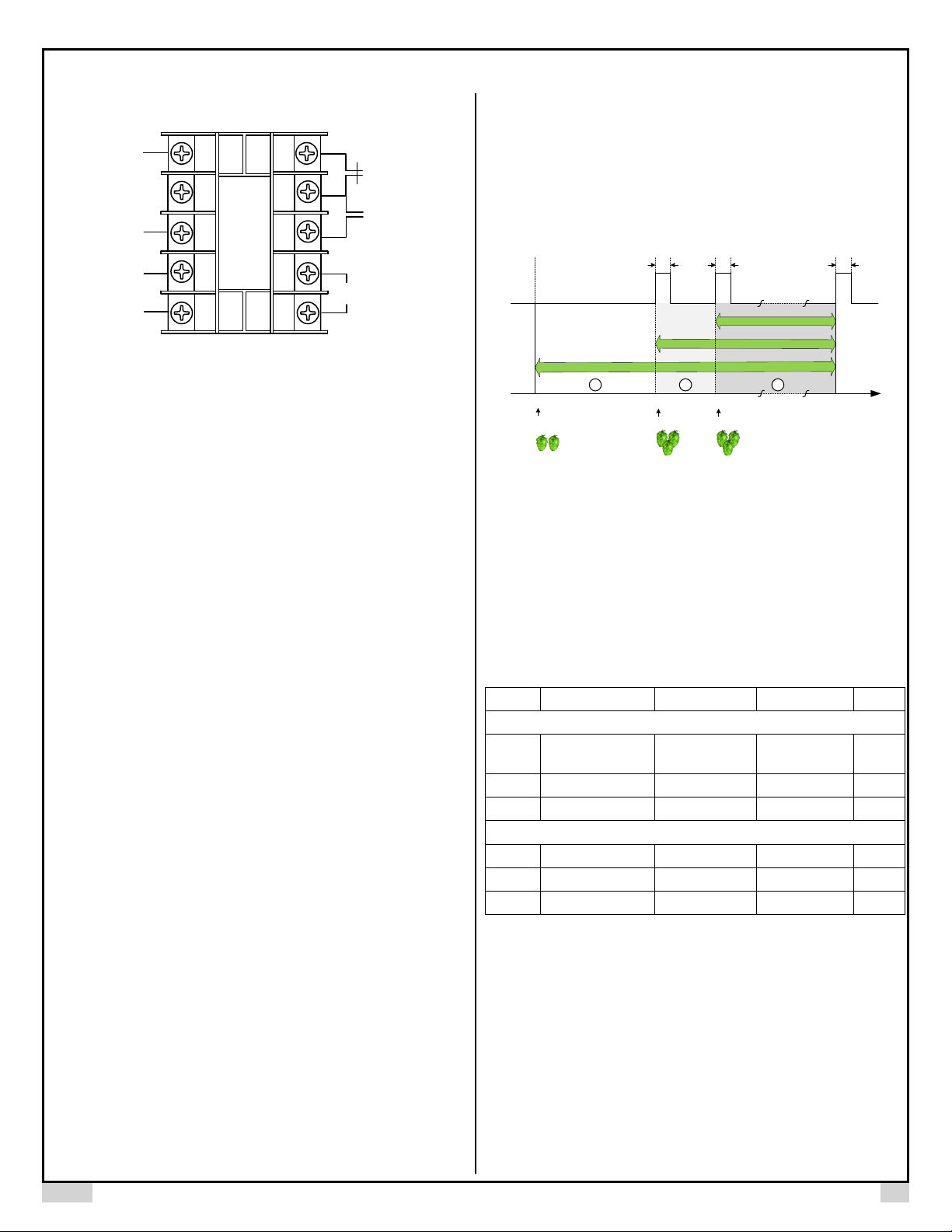
Please see Figure 3 for a schematic diagram showing the relationship between
multiple events and the alarm relay status.
Relay On
Relay Off
Start
Event 1
Ad
1
t
1 2 3
Event 2 Event 3
Ad
2
t
t3
Ad
Boiling Time
End
1). Power for the timer needs to be connected to terminal 9 and 10. The
voltage should be in the range from 90 to 260 VAC.
2). Terminal 6, 7, and 8 are for relay output. Pin 6 and 7 is a pair of normallyopen (NC) contacts. Pin 7 and 8 is a pair of normally-open (NO) contacts. The
relay is a “dry switch” that does not provide power by itself. Please see the
wiring examples in Section 9.
3). Terminal 5 is the start terminal that has the same function as the START
key on the front panel. Please see a note at the end this section.
4). Terminal 4 is the pause/mute terminal that function the same as the
“^/MUT” key on the front panel.
5). Terminal 3 is the reset terminal that function the same as the “V/RST” key in
the front panel.
6). Terminal 1 is the common contact for the terminal 3/4/5. Terminal 2 is
unassigned. There are two ways to operate terminal 3, 4 and 5:
6.a) Connecting a normally open (NO) momentary push button switch between
the terminal (3, 4 or 5) to the COM (1). Please note, the function starts when
you release (or open) the button of the switch, not when you press down the
switch.
6.b) Connecting a DC logic signal (TTL or CMOS or voltage in the range from 3
to 30 VDC) between the terminal (3, 4 or 5) to the COM (1). Please note, the
function is rising-edge triggered. The logic signal should normally be at high
level. The function starts when the signal goes from low to high. If you have an
inverted logic signal, you need to connect a NPN transistor between terminal
and COM; add 10 kohm resistor to the gate for signal input.
5. Operation and Parameters
In JSL-73B timer, an event is defined as an action of adding an ingredient at a
specific time point during the wort boiling process. An event timer starts from
the moment that the ingredient is being added to the wort; it stops when the
wort-boiling process comes to an end. There can be multiple events during the
wort-boiling process. Each event should have a different starting time point, but
they all end at the same time, which is when the boiling process ends.
Figure 3. A schematic diagram of how the event timers and the relay work on
JSL-73B timer.
A special case of the timer is to set it as a stopwatch. In this case, each
window will show a count-up timer. There is no ending point and the relay won’t
pull in. The timer showed in the top window can be re-started while the timer in
the bottom window is still running. The details can be found in section 5.2.
Table 1. Parameters of JSL-73B timer.
Code Description Setting Range Initial Setting Details
Press and hold SET key for 1 second when timer is stopped.
nE
tdir* Timer direction up, dn dn 5.2
Ad
T1
T2 ** Event 2 timer 0 min to t1 20 min 5.4
T3 ** Event 3 timer 0 min to t2 1 min 5.4
The total number of
events
Alarm duration 0 ~ 200 sec 10 sec 5.3
Short press SET key when timer is stopped.
Event 1 timer 0 min to 255 min 60 min 5.4
1 ~ 9 3 5.1
Note *: The parameter tdlr is available only when the number of events nE is
set to 1.
Note **: The event timer t2, t3, and so on., will appear only when the number of
events nE is set to such a number.
5.1) nE, the total number of events. An event can be associated with an activity
such has adding hops or special ingredients. Each event has its own timer. nE
can be set to a number from 1 to 9. The output relay will pull in at the beginning
of all events except the first event, and at the end of the entire boiling process.
So nE is equal to the total number of times you want the buzzer to ring. For
example, if you only add hops at the very beginning of the boiling process, and
2017.05 P2/4
Page 3

AUBER INSTRUMENTS WWW.AUBERINS.COM
want the buzzer to go off when the boiling is done, you will set nE = 1, that is
one event. But if you want to add another hop in the middle of boiling, this is
considered as the second event, the buzzer will go off when the second even
starts.
5.2) tdir, timer direction. This parameter appears only when nE = 1. It can be
set to “dn” (count-down), or “up” (count-up). When nE > 1, this parameter is
not available, and the timer will only count-down.
dn: count-down. The time duration is decided by t1. At the end this single
event, the relay will pull in.
relay will pull in at the end of the event timer t1 and pull in at the beginning of
all other event timers (t2, t3, and so on).
An event timer that starts later should be no longer then the event timers that
start earlier, i.e., t1 ≥ t2 ≥ t3 ≥ …≥ tn. When an event timer is equal to its
prior event timer, this event timer will be ignored. For example, if you set t1 =
t2, timer t2 will be ignored.
The top display window of JSL-73B will show the remaining time before the
next event timer starts; the bottom display window will show the remaining time
to the end of event timer t1, i.e., the end of all events.
up: count-up. When tdir is set to up, event timer parameter t1 will be
disabled, and so the timer will not stop automatically nor activate the
relay. In this mode, the timer functions as two stopwatch timers by
continuously counting up, each display window shows one stopwatch
timer. Press the START key will start or stop the timer in both top and
bottom display; press the RST key will reset both timers to zero; press the
MUT key will restart the timer in the top display window from zero, but it
won’t affect the timer in the bottom window. This function provides a time
reference for users during the mashing process if they want to take a
sample or do some tests of the wort.
5.3) Ad, alarm duration. It is the time duration that you want the relay contacts
to stay closed at the end of each event. The unit is in seconds. The alarm
durations of all events are the same. Ad can be set from 0 to 200 seconds. The
number 0 and 200 are special cases. When Ad = 0, the timer will pause at the
end of each event and activate the relay. User need to press the START key to
resume the timer. When Ad = 200, the timer will continue to the next event,
while the relay contacts will close until user press the MUT key. When Ad is set
to any value between 1 and 199, the timer will continue run time while the relay
pulls in for a certain time duration decided by Ad. For example, when Ad = 5,
the flashing buzzer connected to the output relay will be on for 5 seconds.
Table 2. Timer and relay action under different alarm duration (Ad) settings.
Ad Timer Relay Action Top Display
0 Pause until
pressing
START key
1 ~ 199 Continue to the
next event
200 Continue to the
next event
5.4) tx (i.e., t1, t2, t3, …, tn), the time duration of each event, where x is the
event number, and n is decided by parameter nE. Time duration of an event,
tx, is the boiling time of an ingredient to be added to the boiling wort. t1 is the
first event timer which starts from the moment that the first ingredient is added
until the end of boiling, t2 is the second event timer which starts when the
second ingredient is added until the end of boiling, and so on. Please refer to
Figure 3 for a schematic diagram of the event timers and the relay status. The
Pulls in until
cancelled by
pressing MUT key
Pulls in for a time
duration set by
Ad
Pulls in until
cancelled by
pressing MUT key
Flash “tn” and
“0:00”
Show the
remaining time
before the next
event
Flash “tn” and the
remaining time
before the next
event
6. How to Set Parameter nE and Ad
Press and hold SET key for 1 second, the top display will show nE. Use UP or
DOWN key to change its value shown in the bottom window to the desired
number of events. Press SET key again, the top display will show alarm
duration Ad. Use UP or DOWN key to change it to the desired value, then
press SET key again to save and exit.
7. How to Set Event Timer
Press SET key momentarily, display will show t1, use UP and DOWN key to
adjust the timer to desired value and press SET key to confirm. Please note
that the settings will not be saved until SET key is pressed.
8. Application Examples
We have a buzzer connected to the timer relay and we want it to ring for 10
seconds when it’s time to add a new hop and when the entire boiling process
ends. The beer recipe requires Columbus hop being added at three different
time points for boiling:
1 oz. Columbus, boiling for 60 minutes.
2 oz. Columbus, boiling for 5 minutes.
2 oz. Columbus, boiling for 1 minute.
So the JSL-73B timer should be set like this:
1) Hold the SET key for 1 seconds, then set nE = 3, Ad = 10.
2) Short press SET key, then set t1 = 60, t2 = 5, and t3 = 1.
When we are ready to add hops, press the START key to start timer; then add
1 oz. Columbus hop in the hop bag and immerse the bag in the boiling wort.
After 55 min, the alarm buzzer rings, and the top window flashes “t2” to remind
us that the second event timer has started, and it’s time to add the 2 oz.
Columbus hops. We press the MUT key to temporarily mute the alarm. Then
add 2 oz. Columbus hops to the hop bag. After another 4 min, the alarm buzzer
rings again, and the top window flashes “t3”. We add another 2 oz. hops to the
hop bag. Finally, after another 1 min, the alarm rings and the top window of the
timer show “END”. We turn off the heater and are ready to cool the wort from
boiling temperature.
9. Wiring Examples
9.1) Using switches to start, mute, or reset JSL-73B timer.
2017.05 P3/4
Page 4

AUBER INSTRUMENTS WWW.AUBERINS.COM
Power (120 or 240 VAC) is sent to terminal 9 and 10. The external switches on
terminals 2, 3, 4 and 5 should be momentary type. They are needed only if you
want to control the timer remotely. Otherwise, you can use the front keys on
the timer. The buzzer used in this example is also optional. The buzzer is also
powered by 120 VAC.
Figure 3. Wiring example of JSL-73B.
9.2) Signal controlled by DC logic signal.
Figure 4. Rising-edge triggered signal.
Figure 5. Inverted logic signal.
(End)
Auber Instruments
5755 North Point Parkway, Suite 99
Alpharetta, GA 30022, USA
www.auberins.com
E-mail: info@auberins.com Tel: 770-569-8420
Copyright 2007-2016, Auber Instruments All Rights Reserved.
No part of this manual shall be copied, reproduced, or transmitted in any way without the
prior, written consent of Auber Instruments. Auber Instruments retains the exclusive
rights to all information included in this document.
2017.05 P4/4
 Loading...