

Page 1
AUBER INSTRUMENTS WWW.AUBERINS.COM
2018.06 P1/5
HD220 Dual Output Programmable Humidity Controller
Version 1.2 (June, 2018)
1. Overview
This is a dual-output humidity controller with 8 programmable steps. It contains
one humidity sensor and two independent outputs. One output is for humidifier
and the other is for dehumidifier. The humidity control can be programmed to
vary with different time step setting. Up to 8 humidity-time steps covering 33
days can be programmed. It can be used for tobacco dehydration, sausage
curing, etc. By using both humidifying and dehumidifying, the humidity ratio can
be controlled at a specific value regardless of whether it is in dry or wet
environments.
This controller is a plug-n-play device. No extra wiring is needed for the
humidifier or dehumidifier. Both humidifying and dehumidifying control modes
contain simple on/off operation; they are similar to a mechanical humidistat but
with much higher precision due to adjustable hysteresis band, precise sensor
and digital read out.
Different operation humidity ranges of the two outputs can be set separately.
Once the dehumidifying range is set, the controller program will automatically
limit the humidifying range to prevent both outputs from being turned on at the
same time.
This plug-n-play humidity controller is designed for high relative humidity
(>85%) and condensing environments, where a slight drop in temperature may
cause condensation and could damage other humidity sensors. This controller
equipped with one of the most robust humidity sensors on the market. It can be
fully recovered even immersed in water.
Wireless network connection capability is available in HD220-W. User can
access humidity data and parameter settings of the controller from their smart
phones or tablets. AuberSmart App is available on both iOS and Android
platform. For details, please check the supplementary manual.
2. Specifications
Table 1. Specifications
Humidity Control Range
0 ~ 99.9% RH
Humidity Resolution
0.1% RH
Humidity Accuracy
4% RH
Sensor Working Temperature
- 40 ~ 197° F (- 40 ~ 90° C)
Humidity Control Mode
On/off control.
Humidifying and dehumidifying
Humidity Control Output
15 A, 120 VAC or 240 VAC *
Timer Range
Each step: 0.1 to 99.9 Hours or 1 to 999
Minutes
Timer Resolution
0.1 Hours or 1 Minute
Max Programmable Time
799.2 Hours or 33.3 Days (for total 8 steps)
Audio Alarm
High and low limit
Controller Operating Environment
Temperature
0 ~ 50° C
Dimension
91 x 140 x 46 mm
Input Power
85 ~ 242 VAC, 50 Hz / 60 Hz
Sensor Cable Length
6 ft (2 m)
Power Cable Length
3 ft (1 m)
Warranty
One (1) year for the controller console
* Please note: although both humidity and dehumidity output channel can
handle up to 15A, the total power can be handled by this controller is limited to
1500 Watts due to the restriction of the input power cord.
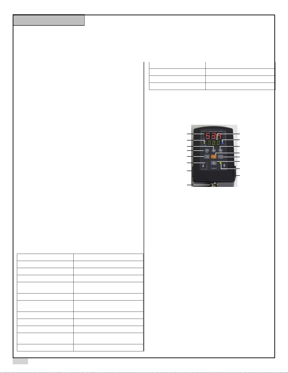
3. Front Panel
Up Key
Down Key
Set Key
Measured Humidity
Start Key
Pause/Stop Key
Mute Key
Prog. Step Key
Run indicator
Set Humidity
WIFI Indicator
Dehumidifier Device Socket
Humidifier Device Socket
Humidifier On Indicator
Dehumidifier On Indicator
Sensor socket
Figure 1. Front Panel.
Measured Humidity Window: In normal operating mode, this window shows
measured humidity. In parameter setting mode, this window shows parameter
name.
Set Humidity Window: In normal operating mode, this window shows set
humidity. In parameter setting mode, this window shows parameter value.
RUN Indicator: This green LED indicator lights up when the controller is
running in multi-step mode. It will be off when the controller runs in single-step
mode.
WiFi Connection Indicator (for HD220-W only): This blue LED indicator
shows WiFi connection status. Please check supplementary manual for details.
SET Key: Access the program settings and parameter settings.
Up Key: Increase parameter value.
Down Key: Decrease parameter value.
PAUSE/STOP Key: Short press it to pause the program; long press it for 4
seconds to stop the program (works only when the program is paused).
START Key: Start or resume executing the program.
STEP Key: Check the current step; or jump to a different step.
Mute Key: Silent the alarm buzzer.
Dehumidifier Socket: Supply power to dehumidifier.
Dehumidifier Indicator: This red LED indicator lights up when the
dehumidifier socket is energized.
Humidifier Socket: Supply power to the humidifier.
Humidifier Indicator: This green LED indicator lights up when the humidifier
socket is energized.
Instruction Manual
Page 2
AUBER INSTRUMENTS WWW.AUBERINS.COM
2018.06 P2/5
4. Basic Operation
Here are the basic operating procedures to use this controller. To fully
understand the functions on this controller, please read the entire manual.
1) Connect the humidity sensor to the sensor socket that is located on the
bottom of the controller. Please check the alignment of the slot on the plug with
the key on the socket. (See section 12 for details.)
2) Plug the controller’s power cord to a wall outlet.
3) Set up the program and system parameters. Please read the rest of this
manual for details.
4) Connect the humidifying and dehumidifying devices to the output sockets on
this controller.
5) Press START key to start running the program.
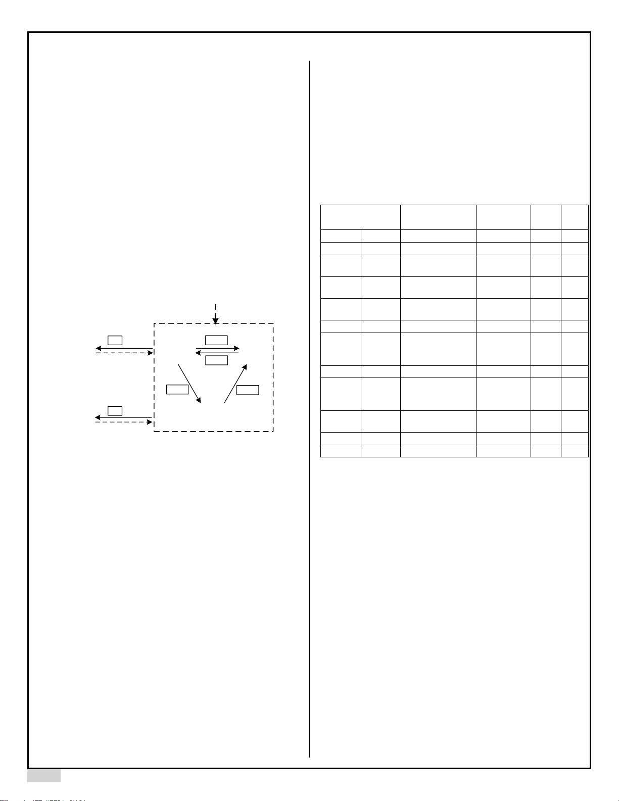
5. Mode Selection
This controller has 5 different modes: program run, program hold, program
stop, parameter setting, and programming mode. Before powering on the
controller, please connect the sensor cable to it. If no sensor is connected, the
controller will show error code “Err”, indicating no sensor is detected.
Program
Hold
Parameter
Setting Mode
Program
Run
Program
Stop
Programming
Mode
2 s
4 s
START
START
STOP
SET
PAUSE
Controller
Power Up
SET
Figure 2. Switching between different modes.
Program Running: The controller executes the saved program. The green
indicator RUN is lit, and the timer is running. The display window should show
the current humidity reading. The controller will send power to its
humidifying/dehumidifying outlets to regulate humidity. When the program is
running, press PAUSE key will put the controller to Program Hold mode.
Program Holding: Controller pauses the time but it still regulates the humidity
at the current set value. The RUN indicator is off. The display window flashes
between the measured humidity value and “Hold”. To resume the program,
press START key. To completely stop the program, hold the STOP key for 4
seconds.
Program Stop: The execution of the program is terminated. Controller outputs
are deactivated and timer is also stopped. The RUN indicator is off. The display
window flashes between the measured humidity value and “Stop”. To start the
program, press the START key. The controller will start regulating the program
from the first step.
Programming Mode: Review and edit humidity set value and set time for each
steps. When the controller is in Program Run, Hold, or Stop mode, press SET
key to enter the Programming mode. Please see figure 4 for details.
Parameter Setting Mode: Review and edit system parameters. When the
controller is in Program Run, Hold, or Stop mode, hold the SET key for 2
seconds to enter the Parameter Setting mode. Please see figure 3 for details.
6. Parameter Setup
Please see Table 2 for a list of parameters and see Figure 3 for the flow chart of
how to set the parameters. Please note that parameters will remain unchanged
unless you press set key to confirm the change.
Press and hold the SET key for 5s to enter the parameter settings. Top display
shows the parameter name and bottom display shows the current value or option
for this parameter. Using up and down key to adjust the value or option in bottom
display. Once finished, press SET key momentarily to confirm and go to next
parameter.
Table 2. List of Parameters.
Code
Description
Setting
Range
Initial
Note
AH
AH
Deviation high alarm
0 ~ 99.9
20.0
1
AL
AL
Deviation low alarm
0 ~ 99.9
20.0
1
HY
HY
Humidity Control
Hysteresis Band
0 ~ 99.9
1.0 2 HYd
Hyd
Dehumidifier
Hysteresis Band
0 ~ 99.9
5.0 3 HYH
HYH
Humidifier Hysteresis
Band
0 ~ 99.9
5.0
4
oFS
Ofs
Humidity Offset
-9.9 ~ 9.9
0
5
AS
AS
Anti-short Cycle
Delay (only for
dehumidifying)
M 0 ~ M 99
(0 ~ 99 min)
M 6
6
PrG
PrG
Program Modes
on, off
ON
7
A-M
A-M
Power
Outage/Startup
Modes
S, M, C
S
8
SFA
SFA
Sensor Failure
Operation
0-0, 0-1, 1-0
0-0
9
TIM
time
Time unit
H, M
H
10
PSD
PSD
App access password
000 - 999
666
11
Note 1. AH, Deviation high alarm; AL, Deviation low alarm:
Assuming measured humidity is PV and set humidity is H. When PV - H is
above AH, the built-in buzzer will turn on (deviation high alarm); when H – PV
is above AL, the built-in buzzer will turn on (deviation low alarm). User can
mute the alarm by momentarily pressing the Mute key. The alarm will remain
inactive until the process value moves out of the alarm zone. Both alarms are
deviation alarms, i.e., if AH = 20%, AL = 30%, and the Set Humidity (H) is 50%
RH, the alarm will be activated if the humidity is above 70% or below 20%. The
alarm function is suppressed at powering up or when the program is jumped
from one step to another step. It will be activated automatically once the
measured humidity enters the none-alarm zone (between H - AL and H + AH).
Note 2. Hy, Humidity Control Hysteresis Band, or Humidity Control Dead Band:
This parameter set up a dead band (between H - Hy and H + Hy) within which
either the humidifier or dehumidifier will not work. The minimum value for Hy is
0.5. The Hy value should not be too small if the system has sluggish response.
Otherwise, it may result in the humidifier and the dehumidifier working against
each other, wasting energy and causing oscillation.
Note 3. Hyd, Dehumidifier Hysteresis Band:
This is the differential band between turn on and turn off the dehumidifier. It is
set to the higher side of the dehumidifier set point (H + Hy). The dehumidifier
will turn on when humidity is above (H + HY + Hyd), and turn off when humidity
Page 3

AUBER INSTRUMENTS WWW.AUBERINS.COM
2018.06 P3/5
is below (H + Hy). For compressor based dehumidifier, the Hyd value should
not be set too small to prevent frequent cycling.
Note 4. HyH, Humidifier Hysteresis Band:
This is the differential band between turn on and turn off the humidifier. It is set
to the lower side of the humidifier set point (H - Hy). The humidifier will turn on
when humidity is below (H - HY – HyH), and turn off when humidity is above (H
– Hy).
For example, if Set Humidity H = 50%, Hy = 5%, Hyd = 3%, HyH = 2%, then
the humidifier will turn on when process humidity is lower than 43% (H - Hy HyH) and turn off when process humidity is above 45% (H - Hy). The
dehumidifier will turn on when process humidity is above 58% (H + Hy + Hyd)
and turn off when process humidity drops below 55% (H - Hy).
Note 5. OFS, Humidity Offset:
OFS (Humidity Offset:) is used to compensate the error produced by the
sensor or input signal itself. For example, if the unit displays 37% when the
actual humidity is 32%. Set parameter OFS = - 5 will make the controller
display 32%. The displayed process humidity = actual measured humidity +
OFS.
Note 6. AS, Anti-short Cycle Delay:
The Anti-short is the delay time to turn on the dehumidifier. If the dehumidifier
is compressor based, compressor should not be turned on immediately when it
is at high pressure (just after turned off). Otherwise, it may shorten the life of
compressor. The Anti-Short cycle delay function can be used to prevent the
rapid cycling of the compressor. It establishes the minimum time that the
compressor remains off (after reaching cutout) before turns on again. The
delay overrides any controller demand and does not allow the compressor to
turn on until the set time-delay value has elapsed. It gives time to release the
refrigerant pressure through evaporator. It typically set to 4- 6 (minutes). The
unit is in minutes. This setting is only valid for dehumidifying control.
Note 7. PrG, Program Mode:
When PrG is set to “ON”, user can program up to 8 steps (Section 5). When
set it to “OFF”, this multi-step function is disabled and controller is in single
step mode. User can only set “H-1” value (without timer t-1) when disabled.
Please be aware that if your controller is in single step mode, the green "RUN"
indicator will be off at all time. The start key, pause key and STEP key are
disabled. You can check the dehumidifier indicator (red on the left) and
humidifier indicator (green on the right) for the socket output status. When the
light is on, the corresponding socket will be activated.
Note 8. A-M, Power Outage/Startup Mode:
This parameter determines what the controller should do in an event of power
interrupt or outage. It also decides how the controller starts the program while
powered up. A-M can be set to three modes: C, S and M.
Mode C. After being powered on, the controller will continue the program from
the where it was powered off. For example, if step 3 is set for 40% and 5
hours, the power was interrupted at 2.1 hours. Then, when the controller power
up, the controller will continue to control at 40% for 2.9 hr.
Mode S. The controller will run the program from step 1 every time the
controller is powered up. This is suitable for situations where the power never
fails, or when the program mode “PrG” is set to “off”.
Mode M. The program will be held at the step at which the controller was
powered off. The controller will hold the humidity at the set value. The
controller lower display will flash "hold" and process humidity alternatively. This
mode is suitable for situations where the operator’s attention is needed after
power interruption occurs.
Note 9. SFA, Sensor Failure Operation:
The SFA defines how the output would be if the sensor fails. It can be set to 00, 0-1 or 1-0. Please refer to Table 3 for details. For example, in some
applications, you may want the dehumidifier to be working and the humidifier to
be off when sensor fails. Hence you need to set SFA to “1-0”.
Table 3. Output of the controller when sensor fails.
SFA
Controller output when sensor fails
0-0
dehumidifier off, humidifier off
1-0
dehumidifier on, humidifier off
0-1
dehumidifier off, humidifier on
Note 10. TIM, Time unit setting:
The Time defines the timer unit setting for its timer function. It can be set to
hour (H) or minute (M). By default, Time is set to H.
Note 11. PSD, App access code (for HD220-W model only):
To prevent the operator from changing the settings by accident over the
AuberSmart App, this access code is required. The default value is 666.
6 8.9
3 6.8
5 sec
AH
20.0
PV
SV
AL
20.0
HY
1.0
HYD
5.0
HYH
5.0
OFS
0
PSD
666
TIM
H
SFA
0-0
6 8.9
3 6.8
SET
SET
SET
SET
SET
SET
SET
SET
SET
High Limit
Alarm
Low Limit
Alarm
Humidity Control
Hysteresis Band
Dehumidifier
Hysteresis Band
Humidifier
Hysteresis Band
Humidity Offset
Anti-short
Cycle Delay
Power Outage/
Startup Modes
Program Modes
Sensor Failure
Operation
Time Unit
App
Access Code
A-M
S
PRG
ON
AS
M 6
SET
SET
SET
PV
SV
PV
SV
PV
SV
PV
SV
PV
SV
PV
SV
SET
End
PV
SV
PV
SV
PV
SV
PV
SV
PV
SV
PV
SV
PV
SV
Figure 3. Flow chart of setting up parameters.
Page 4

AUBER INSTRUMENTS WWW.AUBERINS.COM
2018.06 P4/5
H-1
70.0
PV
SV
T-1
2.0
H-2
60.0
T-2
2.0
68.9
36.8
T-8
0
6 8.9
3 6.8
SET
SET
SET
SET
SET
SET
PV
SV
PV
SV
PV
SV
PV
SV
PV
SV
PV
SV
H-8
0
SET
PV
SV
End
Figure 4. Flow chart of setting up control program.
A total of 8 steps can be programmed in this controller. Each step contains the
set humidity (H-X) and the time duration for this step (t-X), where “X” is the step
number (e.g. step 4 humidity is represented by H-4, and step 4 time is
represented by t-4). Once time is up, it will jump to next step. The time unit can
be set to hour or minute.
To program the humidity profile, briefly press SET key momentarily. Top
display will show “H-1” on the top. Bottom display will show the value for “H-1”.
Use ▲ or ▼key to adjust the humidity to the desired value. Then press SET
key again to save the change and go to next parameter. Top display will show
“t-1”, the preset time for step 1. Use ▲or ▼key to adjust the bottom display to
the desired value, and then press SET key again to save the change and go to
next parameter. Repeat operation till you finish programming all necessary
steps. You can set the time for rest of the steps to zero so that the controller
will skip these steps.
Note: The set value will not be saved unless SET is pressed. The controller will
also return to the normal operating mode if it is left alone for 10 seconds.
7. Check the Status
Step Running Time: how much time has passed since the beginning of the
current step. You can check the Step Running Time while the controller is in
the Program Running Mode:
1) Short press the STEP key once so the display window will show the current
step number “P - X”.
2) Wait about 1second for the step running time to appear in the display
window.
3) Press STEP key again to check the Total Power-on Time (see below) or not
touching any key for 10 seconds so that the display window will show the
humidity reading again.
Total Power-on Time: how much time has passed since the controller is
powered on. You can check the Total Power-on Time in Program Running,
Holding, or Stop Mode:
1) Short press the STEP key twice, you can see “tol” shown in the display
window shortly, and then the Total Power-on Time will be shown.
2) Press STEP again to return to humidity reading.
Once the whole program is finished, the display will show “End” and buzzer will
be ON. Press start key once to restart the program.
8. Program Jump
This controller allows its user to skip part of the program by jumping to a
specified program step. For example, the controller has run 3 minutes in its 2nd
step. If the user wants to skip the rest of the 2nd step and the entire 4th step,
then the user can jump to step 4.
To jump to a specified step:
1) Put the controller in either Program Hold or Stop Mode.
2) Press STEP key so the controller will flash “J-X”, where “J” indicates this
operation is for jumping to a step, “X” is the step number. Use UP or DOWN
arrow key to increase or decrease the step number to desired value, then
press START key to confirm. The display window will show JMP (“JUMP”)
briefly to confirm that jump is accomplished. Then controller will execute the
step, RUN indicator will lit, and display window should show humidity reading.
9. Alarm Buzzer
The controller has a build-in buzzer. Under the following situations, the alarm
buzzer will be triggered:
1) When the humidity alarm is triggered, the buzzer will keep on beeping until
the MUTE key is pressed.
2) When a program step (other than the 8th step) is finished, the buzzer will
beep twice.
3) When the entire program is finished (the 8th step), the buzzer will keep on
beeping until the MUTE key is pressed.
When the alarm buzzer is beeping, you can press MUTE key to mute the
alarm.
10. Quick Operation Guide
• If you see “Err” message in the display window, check the sensor
connection.
• To run the program: if the controller is in Hold or Stop mode, press START
key. The RUN indicator should lit up.
• To hold the program: when the program is running (RUN indicator on),
short press PAUSE key to put the program on hold.
• To stop the program: put the program to Hold mode, then long press the
STOP key for 4 seconds until you see “Stop” in the display window.
• To set up program steps: press SET key.
• To set up system parameters: long press SET key for 2 seconds.
• To mute the alarm: press MUTE key.
• To check the current step number and the step running time: in the
program running mode, press STEP key once, the display will show “P-X”,
where X is the current step number, then the display window will show the
elapsed time in the current step.
• To check the total time since the controller is powered up: in the program
running mode, press STEP key twice. The display window will show “toL” and
then it will display the total time since controller is powered up.
• To start from a specific step (or jump to a specific step): when the program
is on hold or stopped, press STEP key once, it will show “J-X”, where X is the
current step number. Use the UP or DOWN key to change the step number to
the desired value, then press START key to confirm. The display will show
JMP (“JUMP”) for a second and then the controller will start executing the
specified program step.
Page 5

AUBER INSTRUMENTS WWW.AUBERINS.COM
2018.06 P5/5
11. Connect the Sensor to the Controller
The connector of sensor contains a slot for fitting pin connection. It also has a
spring lock to prevent disconnections from accidental pulling on the cable.
To install the sensor to the controller: 1) Identify the key on the male sensor
connector (Figure 5, a) and the notch on the female connector (Figure 5, b). 2)
Hold the tail of the female connector, align the notch and the key, and push the
female connector forward.
To remove the connector, hold the spring loaded collar on the female
connector and pull it back. Please see Figure 6.
(a)
(b)
(c)
Figure 5. Install the sensor.
Figure 6. Remove the sensor.
Auber Instruments
5755 North Point Parkway, Suite 99
Alpharetta, GA 30022, USA
www.auberins.com
E-mail: info@auberins.com Tel: 770-569-8420
Copyright 2007-2018, Auber Instruments All Rights Reserved.
No part of this manual shall be copied, reproduced, or transmitted in any way without the
prior, written consent of Auber Instruments. Auber Instruments retains the exclusive
rights to all information included in this document.
 Loading...