

Page 1
AUBER INSTRUMENTS WWW.AUBERINS.COM
A
Instruction Manual
Instruction Manual for EZBoil® DSPR320
Version 1.0 (August, 2018)
Caution
This controller is intended to control equipment under normal operating
conditions. Failure or malfunction of the controller may lead to abnormal
operating conditions, which result in personal injury or damage to the equipment
or other property. Devices (limit or safety controls) or systems (alarm or
supervisory) intended to warn of or protect against failure or malfunction of the
controller must be incorporated into and maintained as part of the control system.
Installing the rubber gasket supplied will protect the controller front panel from
dust and water splash (IP54 rating). Additional protection is needed for higher
IP rating.
This controller carries a 90-day warranty. This warranty is limited to the
controller only.
1. Specifications
Table 1. Specs of DSPR320.
Input type RTD (Resistance Temperature Detector): PT100
Accuracy ± 0.2% of full scale
Sensor input range 0°F ~ 932°F, -17°C ~ 500°C
Response time ≤ 0.5 s
Display resolution 1°C or °F
Control mode temperature, power
Program step Up to 9 steps in each mode
Timer range 00 H 00 M to 99 H 00 M
Main output 12 VDC for solid state relay
Relay output 3 A for resistive load. 1 A for inductive load
Number of relays 2
Power supply 85 V ~ 260 V AC / 50 ~ 60 Hz
Power consumption ≤ 5 Watt
Working ambient
temperature
Dimensions 48 x 48 x 100 mm (W x H x D, from the front panel to the back)
Mounting cutout 45 x 45 mm
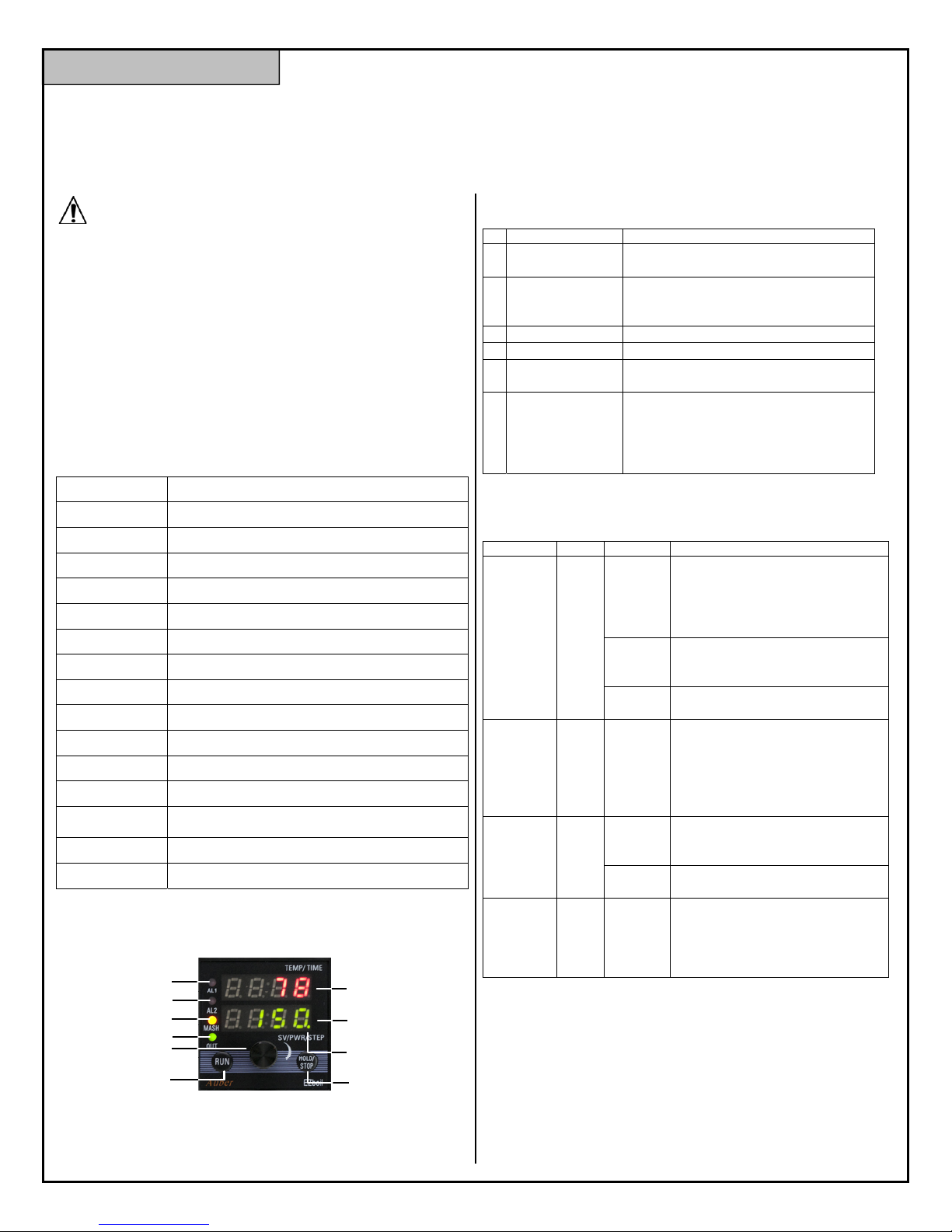
2. Front Panel
0ºC ~ 50ºC, 32ºF ~ 122ºF
4
5
6
1
2
7
8
3
9 10
Figure 1. The front panel of DSPR320.
2.1. Display
Table 2. Front panel display.
# Name
1 Top Display
2 Bottom Display
3 AL1 Indicator (red)
4 AL2 Indicator (red)
5 MASH Mode
Indicator (yellow)
6 Output Indicator
(green)
2.2. Key Functions
Table 3. Key functions
#
Key
8 Knob
9 RUN
10
Combination
3. Wiring Terminals
The pin assignment of the back terminals of DSPR320 is shown in Figure 2 and
the descriptions of each terminal are given in the table below.
HOLD
/STOP
RUN
+
KNOB
Descriptions
Temperature reading and step-timer.
Parameter names.
Set value, step number, and program
status.
Parameter values.
Light up when Relay 1 (AL1) pulls in.
Light up when Relay 2 (AL2) pulls in.
Light up when controller is in MASH
mode.
Light up when the controller is sending
control signal to the SSRs. When it
flashes, the percentage of time of it
being lit up indicates the percentage of
power that is being sent to the SSRs.
ction
Short press
Long press
Rotate
Short press
Short press
Long press
Hold
down the
RUN key
and press
the knob
Functions
Press the knob to bring up the
Quick Access Menu.
Press the knob to select a
parameter or to save the
parameter value.
Press and hold the knob 3
seconds to bring up the Main
Menu.
Rotate the knob to browse and
change parameter values.
Start the program.
Resume the timer if timer is
paused.
Mute the on-board buzzer and/or
cancel the relay action if
temperature alarms are triggered.
Pause the timer.
Hold it down for 2 seconds to stop
the program.
End the program and stop all
outputs.
Go back to the previous
parameter in the menu list.
2018.08 P1/11
Page 2
AUBER INSTRUMENTS WWW.AUBERINS.COM
AL2
-
SS R
7
+
8
9
AC
85~260V
10
RTD
AL 1
1
13 14 6
2
3
R
4
R
5
W
Figure 2. Terminal assignments of DSPR320.
Table 4. Back terminals of DSPR320.
Pin # Descriptions
1 Relay 1 (AL1)
2
3 Probe input (PT100 RTD). Two red leads should be connected to pin 3
and 4.
4
5
6 Control output (12 VDC), pin 7 is the positive and pin 6 is the negative.
7
9 Power input (85 V ~ 260 V AC)
10
13 Relay 2 (AL2)
14
4. Getting Started
Before you start using this controller, please read the manual carefully. This
section only provides a brief description on some of the most basic operations of
this controller. Please read the later sections in this manual to understand how this
controller works and learn more about each parameter.
4.1. Power Up
To test the unit and get familiar with all the features of this controller, please
connect a PT100 RTD probe and then supply the 120 V or 240 V AC power.
4.2. Displayed Information
When the controller is powered up for the first time, the top display will show
current probe reading, and the bottom display will show the program status
“STOP”.
When the program is running but the temperature has not yet reached the setvalue of the current step (i.e., the step-timer has not started yet), the top window
shows the current temperature reading, and the bottom display will flash between
the current set-value and the current step number (Figure 3). When the step-timer
has started, the top window will show the probe reading and the time alternatively,
and the bottom window will still show the current set-value and the current step
number alternatively (Figure 4). If the set-value has the letter “P” display on its left,
that means this is a percentage value of power, not a temperature value.
7 8
1 5 0
7 8
m - 1
Figure 3. Two display screens when the step-timer has not started.
1 4 9
1 5 0
00:45
m - 1
Figure 4. Two display screens when the step-timer has started.
There are four LED indicators on the left side. The top two red LED are
synchronized with the relay AL1 and AL2 status respectively. The third LED is
yellow, and it lights up if the controller is at MASH mode. The last green indicator
is synchronized with the output signal to the external SSR.
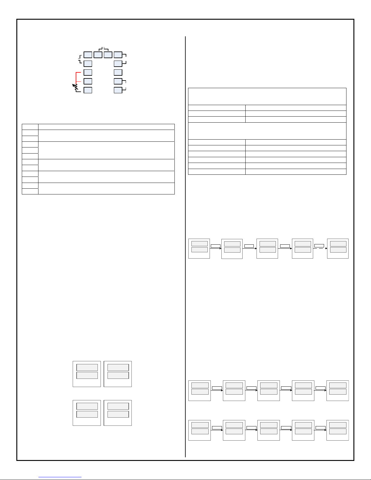
4.3. Understand the Menu Structure
The table below shows the menu structure of DSPR320 and how to access the
menu.
Table 5. Menu structure of DSPR320.
(Short-press the knob to bring up the Quick Menu; rotate the knob to browse different
RST (n/y)
STEP (1 ~ 9)
MODE (Mash/Boil)
(Hold down the knob for 3 seconds to bring up the Main Menu; rotate the knob to
browse different menu items; press the knob again to select. )
mPRG
bPRG
mSET
bSET
RELY
SYST
Quick Access Menu
options; press the knob again to select.)
Reset the program
Jump to the selected step
Select mode
Main Menu
Mash mode program
Boil program
Mash-step settings
Boil-step settings
Relay configurations
System configurations
4.4. Select Mash or Boil Mode
There are two program modes: MASH and BOIL. By default, the controller is at
MASH mode. If you want to run the program in Boil mode, please press the knob
to bring up the Quick Access Menu. Next, rotate the knob clock-wise till you see
“MODE” in the top display and “BOIL” in the lower display. Then, press the knob
again to confirm the selection. The MASH indicator will light up if the controller is
in MASH mode, and it should turn off if the controller is in BOIL mode.
Press
KNOB
MODE
B O I L
stop
7 8
Press
KNOB
R S T
N
Keepturning
KNOB
STEP
1
Keepturning
KNOB
MODE
MASH
Figure 5. Select Program Mode on DSPR320.
4.5. Adjust Parameters
All parameters are divided into four groups in the Main Menu: mSET (mashing
step settings), bSET (boiling step settings), RELY (relay settings), and SYST
(system settings). Press the knob for 3 seconds to go the Main Menu and turn the
knob to select the desired parameter group to edit. Please refer to Section 7 of this
manual for the detailed explanation of each parameter.
4.6. Enter the Program
Press down the knob for 3 seconds to go the main menu, the first two items are
mPRG (Mash Mode Program) and bPRG (Boil Mode Program). Rotate the knob
to select which program to enter and press the knob again to confirm.
There are maximum 9 steps can be entered in each mode. For each step, the user
will be asked to enter the set-value and the step-timer. The Figure 6 below shows
the operations for how to enter the set-value of the Step 1 of the Mash Program.
And the Figure 7 shows the same operations for Boil Program.
stop
7 8
Press
KNOB
3sec
GOT O
mPRG
Press
KNOB
M1 - s
M 0
Turn
KNOB
M1 - s
M1 5 0
Press
KNOB
M1 - t
0 0:0 0
Figure 6. Entering the Mash Program.
stop
7 8
Press
KNOB
3sec
GOT O
bPRG
Press
KNOB
b1 - s
p 0
Turn
KNOB
b1 - s
P 2 5
Press
KNOB
b1 - t
0 0:0 0
Figure 7. Entering the Boil Program.
2018.08 P2/11
Page 3
AUBER INSTRUMENTS WWW.AUBERINS.COM
The set-value can either be a temperature value (with letter “M” display on the left)
or a percentage number (with letter “P” displayed on the left) of the power output.
The user can rotate the knob to select from 0% to 100% power and from 0 to
932 °F/°C. Press the knob to confirm the value and go to the timer setting.
The step-timer can be set in the HH:MM format, ranging from 00:00 to 99:00, or a
special code which can be SKIP, HOLD, END, or CONT. Please see later sections
for details. If the step-timer a step is set to END or CONT, the user won’t be
prompted with the next step.
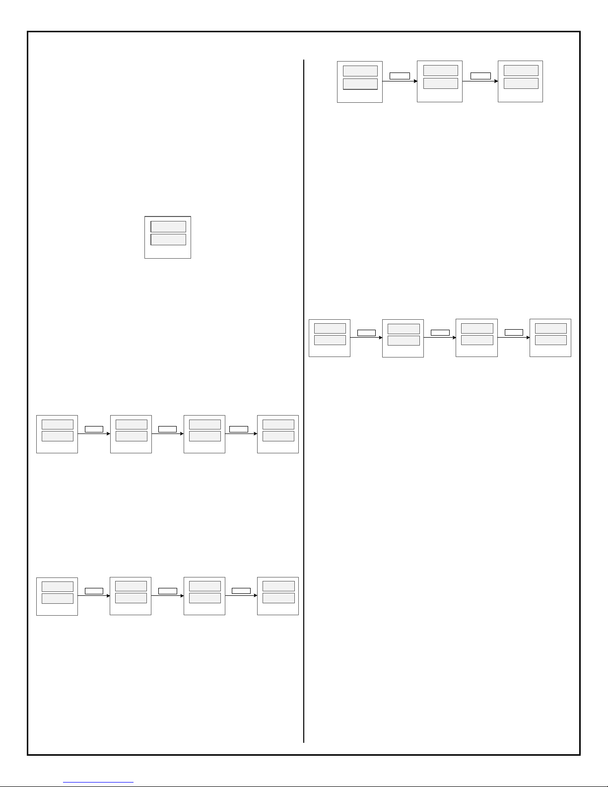
4.7. Start the Program
Simply press down the RUN key to start the program. The top window will show
“RUN” shortly and then show probe reading and start running the first valid step.
RUN
1 5 0
Figure 8. The top window shows “RUN” when the program starts.
4.8. Make Adjustment On-the-Fly
This controller offers a quick way for users to adjust the set-value and the steptimer of the current step without going back into the programming menu. It also
allows the program to be jumped from the current step to any other valid step in
the program.
a) Change the set-value. When the lower display shows the current set-value,
simply turn the knob in either direction to start editing the value. A flashing dot will
appear at the lower right corner to indicate the set value is being editing. Keep
turning the knob till the desired set-value is shown in the lower window. Then press
the knob to confirm the change, otherwise the new value won’t be saved.
7 8.
1 5 0.
Turn
KNOB
7 8.
1 5 0.
Turn
KNOB
7 8.
1 5 5.
Depress
KNOB
7 8.
1 5 5.
Figure 9. Changing the set-value while the program is running.
b) Change the step-timer. When the lower display shows the current step number,
turn the knob in either direction to start editing the step-timer. A flashing dot will
appear at the lower right corner to indicate the new value hasn’t been saved yet.
Press the knob again to confirm the change, otherwise the new value won’t be
saved. The Figure 10 below shows this operation when the temperature is still
being ramping up to the step’s set-value. So, the top window only shows the
current probe reading. If the step-timer had started, the top window will show the
current time.
7 8.
m - 1.
Turn
KNOB
7 8.
0 0:4 5.
Turn
KNOB
0 0:5 0.
7 8.
Depress
KNOB
7 8.
m - 1
Figure 10. Changing the step-timer while the program is running.
c) Pause the timer. When the temperature reaches the timer-start-point, the steptimer will start counting down time. The user can manually pause the timer by
short-pressing the HOLD key. When the timer is paused, the top window will show
“HOLD.”. To resume the current step- timer, press the RUN key shortly and the
controller will show “RUN” in its top window. The Figure 11 shows how to pause
the timer.
0 0:4 5.
m- 1.
Figure 11. Operations to pause and to resume the step-timer.
When the timer is paused from the key pad, a dot will also appear in the right
corner of “HOLD.” indicates that the timer is temporarily paused and it can be
resumed. This is different from setting/changing the step-timer to HOLD, where
the timer display is “HOLD” (no dot) and pressing the RUN key will make the
program continue to the next step.
d) Jump to another step. While the program is running, it can be jumped from
the current step to another step in the program. This operation is not valid if the
program is ended or stopped. The operation is shown in Figure 12. Press the knob
to bring up the Quick Access Menu. The top window will show “STEP” and the
current step number will be shown in the lower window. Turn the knob to find the
desired step number and press down the knob to confirm. If you select a valid step
number, the controller will jump to the selected step and executing the new step.
If you select the current step number or a non-valid step number, the controller will
take no action and simply return to the main operation interface. Here, a non-valid
step refers to a step whose step-timer is set to SKIP or a step behind the last step
of a program.
7 8.
1 5 0.
Press
KNOB
Figure 12. Jumping from one step to another while the program is running.
Please note that all changes that the user makes from the main interface are
temporary. It doesn’t affect the programs that have been saved in the mPRG or
bPRG. The controller will always retrieve the set-value and the step-timer value of
the next step from the saved program.
4.9. End or Stop the Program
In DSPR320, End and Stop are different status. When a program has come to its
end, whether the controller will enter the End or the Stop status depends on the
parameter EO (Ending Option for Mash Mode) and bEO (Ending Option for Boil
Mode). Please refer to section 5.7 for details.
Ways to End a program:
a) Wait till the controller finish executing all the programmed steps.
b) Change the step-timer to “END”. The program will come to its end when the
temperature reaches the timer-start-temperature.
Ways to Stop a program:
a) Press and hold the “STOP” key for about 3 seconds to end the program and
stop all outputs.
b) Reset the program by going to the Quick Access Menu and select “RST/Y”.
c) Switch the Operation Mode from one to another will also end the current
program.
d) Power off the controller and power it on again.
5. Understand the Controller DSPR320
5.1. Program Mode
In DSPR320, a Program Mode, or a Mode, can save a program with up to 9 steps.
There are two Modes on DSPR320: MASH and BOIL. The Program Mode is
indicated by the MASH LED indicator. The intended use of MASH Mode is to
control water or wort temperature during a mashing process. The default setvalues of all steps in MASH Mode are 0 degree. The temperature unit depends on
Press
HOLD
Step
1.
HOLD.
1 5 0.
Turn
KNOB
Press
RUN
STEP
RUN
m- 1.
Press
RUN
KNOB
3
1 6 0.
2018.08 P3/11
Page 4
AUBER INSTRUMENTS
the C-F setting in the SYST menu. The intended use of BOIL Mode is to bring
water or wort to its boiling point and remind the user to add hops. The default setvalues of all steps in BOIL Mode are 0% of power. It is displayed as “P 0”, where
the letter P indicates this is a percentage value of power.
Despite the difference in the default set-values, the DSPR320 controller does allow
the user to change set-values freely from temperatures to power percentages, or
vice versa. Any step in MASH mode can be a power-control step (boiling step),
and any step in BOIL mode can be a temperature-control step (mashing step).
This feature gives users a great flexibility to customize the desired heating profiles
per their brewing recipes and control automation needs.
Please note that switching Program Mode while a program is running will result in
the program being terminated immediately. This operation is not recommended.
5.2. Program
A Program refers to a series control steps that has been saved under a Program
Mode (MASH or BOIL). A program can have no more than 9 steps. When the user
edits a program, if a step’s step-timer is set to END, the user won’t be asked to
enter settings for the next step.
When the controller runs a program, it always starts from Step 1 or the first valid
step and ends at either at the step where the step-timer is set to END or at Step 9
if it exists.
The MASH Mode has a special feature that allows the controller to continue to run
the program saved in BOIL Mode automatically when the Mash program is finished.
To use this feature, the last step in the MASH Mode should be set to CONT instead
of END by turning the knob counter-clockwise for a full turn.
The user can go to mPRG (MASH mode program) and bPRG (BOIL mode
program) in the main menu to enter or edit the programs.
Step settings in mPRG and bPRG are named in this format: aX-B, where:
a: can either be letter m or b to indicate MASH mode or BOIL mode.
X: a numeric number ranging from 1 to 9.
B: can either be letter S or t where
S: set-value.
t: step-timer.
For example, the parameters of the Step 1 of MASH mode are m1-S and m1-t
while the parameter of the first step of BOIL mode are b1-S and b1-t.
5.3. Step
A step can be considered as one of many sections that consist a program. It
defines the temperature or power percentage that the controller should maintain
for a certain duration of time. A step is exclusively referring to the time period when
the temperature has reached a pre-defined timer-start-point and the step-timer is
counting time. The beginning of a step is when the step-timer starts and the end
of a step is when the step-timer ends. In a program, the sections between steps
are transition sections, or called ramp sections. The controller doesn’t regulate the
ramp-up or ramp-down speed.
The settings of a step consist of the set-value and the step-timer. The step-timer
only starts counting when the temperature has reached a pre-defined timer-startpoint (see section 5.6 for details).
5.4. Ramp Sections
In DSPR320, program sections between steps are called ramp sections. Some of
the relay functions are closely associated with the ramp sections, hence a clear
definition of each section is necessary. A STEP section is exclusively referring to
the time period when the temperature has reached a pre-defined timer-start-point
and the step-timer is counting time. The section prior to the start of a STEP as well
as its step-timer is referred as the RAMP section of a step. A ramp section where
the temperature needs to be ramped up is called HEAT section. A ramp section
where the temperature needs to be cooled down is called COOL section. A RAMP
WWW.AUBERINS.COM
section and a STEP section together are referred as an Extended Step (EXTN)
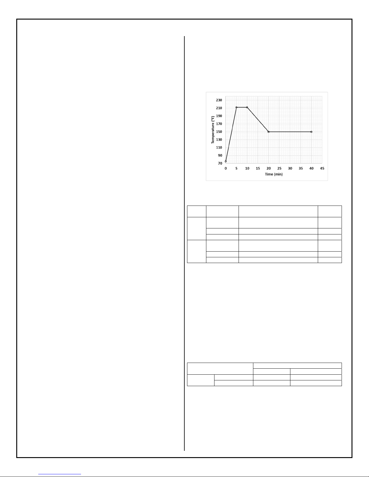
section. The plot in Figure 13 shows a short two-step program to illustrate what
the different sections are. The description of each section is given in the table.
Please note that the controller determines whether a section is HEAT or COOL
by comparing the current probe reading and the step’s set-value instead of
comparing the set-values of two steps.
Figure 13. A two-step program to illustrate different program sections.
Table 6. Program sections of the two-step example program.
Step # Time Range Description Section
0 ~ 5 min Ramp section of Step 1, which is a HEAT
1
5 ~ 10 min
0 ~ 10 min
10 ~ 20 min Ramp section of Step 1, which is a COOL
2
20 ~ 40 min Step 2
10 ~ 40 min Extended Step 2 EXTN
To determine whether a transition section is HEAT or COOL, the controller
compares the current probe reading against the step’s set-value instead of
comparing the set-values of two steps. This comparison only happens when the
program is in a transition section, i.e., when the step-timer of the next step hasn’t
yet started.
However, the boiling steps (power-control steps) are handled differently since
there is no set-value for boiling steps. For boiling steps, the controller uses the
bTSP (boiling timer-start-point) for comparison purpose. Table 7 listed the
different situations of how the controller determine HEAT or COOL of a ramp
section.
Table 7. Determine HEAT or COOL between two steps.
To Step (n+1)
From Step
(n)
Mashing Step
Boiling Step
5.5. Step-Control Mode
The step-control mode, or control mode, refers to how the power is regulated at
a step, which can either be temperature-control or be power-control. In
temperature-control mode, the goal is to raise and maintain the water or wort
temperature at the specified value. The steps that have set values in temperature
(0 ~ 932 °F/°C) use temperature-control mode and these steps are sometimes
referred as mashing steps for convenience. In the power-control mode, the goal
is to bring water or wort to boil by raising the water or wort temperature above
section
Step 1
Extended Step 1 EXTN
section
Mashing Step Boiling Step
PV vs SV PV vs bTSP
bTSP vs SV bTSP vs bTSP (N/A)
Type
RAMP,
HEAT
STEP
RAMP,
COOL
STEP
2018.08 P4/11
Page 5

AUBER INSTRUMENTS WWW.AUBERINS.COM
No
No No
A
No No
certain threshold and then let the user to adjust the power output percentage
manually. Steps that have set values in percentage (0% ~ 100%) use power-
control mode and these steps are sometimes referred as boiling steps for
convenience.
For any step in a program, the control mode can be either temperature-control or
power-control. The MASH or BOIL mode doesn’t impose any constraint on the
control mode of any step in its program. When entering the set-value for a step,
the user can simply select either a power percentage number or a temperature
value as the set-value.
Please note that “mashing step” or “boiling step” refers to how the power is
controlled for a particular step, while the “mash mode” or “boil mode” refers to
the program mode that is intended to be used for the mash or boil process.
5.6. Set-Value
The set-value of a step can be either a power percentage value (from 0% to 100%)
or a temperature value (from 0 to 932). The percentage numbers and the
temperature values together make up a combined list of available set-values:
0%, 1%,....99%, 100%, (bo) (ma), 0, 1, 2, … 931, 932.
When editing the set value, the user can rotate the knob to select the desired value.
Turning the knob clockwise will increase the value, and turning the knob counterclockwise will decrease the value. When the value changes from percentage to
temperature, the lower window will show “MA” shortly to remind the user the set
value is temperature value for mashing. Conversely, when turning the knob
counter-clockwise and as the value changes from temperature to percentage, the
lower window will show “BO” shortly to remind the user the set value is power
percentage for a boiling step. All temperature values have the letter “M” displayed
on the left side, and all percentage values have the letter “P” will be display on the
left side to indicate these are percentage values. For example, 0% is displayed as
“P 0” and 0 degree is displayed as “m 0”.
When the program is running, temperature set-values will NOT have the letter “M”
displayed on the left, but the percentage values do have the letter “P” on the left.
5.7. Step-Timer
The step-timer defines the time duration of a step where the temperature or the
power should be maintained at its set-value. The timer can be set to anywhere
between 0 minute to 99 hours. The time duration is displayed in the format of
HH:MM.
The step-timer setting can also be a special command which tells the controller
how to handle this step instead of counting down time. The special command can
be SKIP, HOLD, END, or CONT. The meaning of a command is explained in the
table below. Please note that “CONT” is not available to the BOIL program mode.
Table 8. Special commands of step-timers.
Command Description
SKIP Bypass this step.
HOLD Hold the program at the current step. Press RUN key to continue to
the next step.
END End the program.
CONT End the MASH Program and continue to execute the first step of the
BOIL program. Only available to MASH Program.
When the controller executes a step, it won’t start the step-timer or execute the
special command until the probe reading has reached a timer-start-point. For
temperature-control steps (mashing steps), the timer-start-point is determined by
tSP, which defines a two-sided deviation band around the set-value (see Figure
14). For power-control steps (boiling steps), the timer-start-point is determined by
bTSP, which defines an absolute temperature value above which the timer should
start. Once this temperature is reached, the controller will start counting down time
until the time is reached, or execute the special command. Once the timer starts,
it won’t stop nor pause because of the probe temperature drops output of the timerstart-point. However, the user can manually pause the timer by pressing the HOLD
key, and then resume the timer by pressing the RUN key.
230
210
190
170
150
130
Tem p er a t u r e(° F)
110
90
70
Boilin gstep
bTSP
SV+tSP
Mashingstep
0 5 10 15 20 25 30 35 40 45
Time(min)
SV‐tSP
Figure 14. The timer-start-point of boiling steps and mashing steps are defined
differently.
5.8. End or Stop the Program
When the last step of a program is executed, the program ends and controller will
either show “END” or “STOP”. In DSPR320, End and STOP are different status.
STOP means the controller has turned off all outputs, including the main SSR
output as well as both relays. END means the program has come to an end, but
the controller will continue to regulate the temperature or the power per the setvalue of the last step. See Table 9 for a comparison between these two statuses.
Table 9. The differences between END and STOP.
Main Output
Relay Output
larms
END
Yes
STOP
When a program has come to its end, whether the controller will enter the END or
STOP status depends on the parameter EO (Ending Option for Mash Mode) and
bEO (Ending Option for Boil Mode).
By default, both EO and bEO are set to OFF, which means that once a program
has ended, there will be no output from the controller. The controller will show
current probe reading in the top window and show “STOP” in the bottom window
(Figure 15).
7 9
stop
Figure 15. DSPR320’s display when a program is stopped. All outputs are turned
off.
If EO and/or bEO is set to ON, the controller will continue to regulate the
temperature if the last step is a temperature-control step, or to regulate power if
the last step is a power-control step. The controller will show the current probe
reading and “END” alternatively in the top bottom window. The bottom window
will show the set-value of the last step in the program (in Figure 16, the set-value
is 80). The OUT indicator will show the output status accordingly.
2018.08 P5/11
Page 6

AUBER INSTRUMENTS WWW.AUBERINS.COM
… …
…
…
…
END
8 0
7 5
8 0
Figure 16. DSPR320’s display when a program is ended. The OUT indicator is
on as the controller still tries to maintain the temperature at set-value.
Once the program has ended or stopped, pressing the RUN key won’t start the
program again. The user needs to reset the controller, by either going to RST in
the Quick Access Menu or cycle the power supply to the controller, before the
program can be started again.
5.9. Use Relays to Assist the Brewing Process
The DSPR320 is equipped with two build-in relays, Relay 1 (labelled as AL1) and
Relay 2 (labelled as AL2). They are identical in terms of their capability and
specifications. There available Relay Mode settings are: ALAM, BEEP, ALBE,
RAMP, HEAT, COOL, STEP, and EXTN. Please see section5.3 and 7.5 for more
details.
The functions of the relays can be divided into three main groups:
a) Temperature alarms: ALAM and ALBE.
b) Event remainder: BEEP.
c) Program-section control: RAMP, HEAT, COOL, STEP, and EXTN.
For the first two groups, temperature alarms or event reminder, the main
application is to use the relay to drive an external buzzer.
With the functions in the third group, the controller can complete more complexed
home brewing automation tasks, such as turning on an additional heater during
the ramp-up section of certain steps, turning on the wort pump during all mashing
steps, or turning on a circulation pump for chiller during ramp-down sections when
wort needs to be cooled down. An example of how to use the replay to control
pumps are given in the section 10.1 of this manual.
6. Quick Access Menu
The Quick Access Menu has three functions as shown below.
RST -- reset the program
STEP -- jump to another step
MODE -- select Program Mode
Table 10. Quick Access Menu.
Top
Disp.
RST
Bottom
Disp.
N
Y
(Rotate the knob to browse, press the knob to confirm the
No effect. Return to the normal operation mode.
Reset the program, stop all outputs. The user
can start the program again by press down the
Functions
selection.)
RUN key.
When a program is running, select a valid step
number to jump to the selected step.
Selecting the current step number has no
STEP 1 ~ 9
effect.
Selecting non-valid step number, i.e., a step
that doesn’t exist in the current program or a
step has been set to SKIP, has no effect.
Stop all output and switch to MASH mode if
MASH
MODE
BOIL
current mode is BOIL.
No effect if current mode is MASH.
Stop all output and switch to BOIL mode if
current mode is MASH.
No effect if current mode is BOIL.
To bring up the Quick Access Menu, simply press the knob shortly. When the
controller is not executing any program, i.e., the controller is at the END or the
STOP status, press the knob will bring up the RST function. If a program has been
started, press the knob will bring up the STEP function. The user can rotate the
knob to select the desired function. To confirm the selection, press the knob again.
The table below listed the details of each function in the Quick Access Menu.
7. Main Menu
Program settings and parameters are grouped into 6 submenus.
mPRG – the program of Mash Mode.
bPRG – the program of Boil Mode.
mSET – settings for all mashing (temperature-control) steps.
bSET – settings for all boiling (power-control) steps.
RELY – settings for relay AL1 and AL2.
SYST – system parameters.
To bring up the Main Menu, press down the knob for 3 seconds. Then the top
window will show “GOTO” (go-to) and the bottom window will show the first item
in the menu list, which is “mPRG” (mPRG). Turn the knob to find the correct submenu, and then press down the know to select the item. The parameters in each
sub-menu are listed and explained below.
7.1. mPRG – Mash Program
The user can enter or edit the Mash Program in this sub-menu. Only the settings
for Step 1 is listed and described in Table 11. Steps in the rest of the program are
identical to Step 1.
Table 11. mPRG menu.
Display Name Description Range Default Note
m1-s m1-S Set-value 0% ~ 100%, 0 ~
m1-t m1-t Step-timer CONT, END, HOLD,
…
m9-S m9-S …
m9-t m9-t …
mPRG
0 °F/°C 1
932 °F/°C
00:00 2
SKIP, 00:00 ~ 99:00.
… …
… …
… …
Note 1. Set-value can be a percentage value or a temperature value,
corresponding to a boiling step or a mashing step respectively. The unit of set
temperatures is decided by the C-F setting in the SYST menu.
Note 2. When the temperature has reached the timer-start-point of a step, the
controller will start the step-timer or execute the special command. The special
commands are explained below:
CONT – Continue executing the Boil Program when the Mash Program is over.
END – End the program.
HOLD – Hold the program at the current step till the user press the RUN key.
SKIP – Bypass this step.
However, the special command SKIP is an exception. If a step-timer is set to SKIP,
this step will be bypassed when running the program, and the step number will
become invalid in the current program. For example, in a 4-step mashing program,
if the user changes the m2-t to SKIP, the controller will only execute Step 1, 3, and
4, and the user can’t not jump to the Step 2 of this program.
The command CONT is only available in MASH program mode. To select CONT,
turn the knob counter-clockwise for a full turn when you see END. If the step-timer
is set to END or CONT, the controller won’t ask the user to enter settings for the
rest of steps. And so, the rest steps don’t exist to this particular program.
2018.08 P6/11
Page 7

AUBER INSTRUMENTS WWW.AUBERINS.COM
3
A
5
7.2. bPRG – Boil Program
The user can enter and edit the BOIL program in this sub-menu. The settings of
the BOIL program are the same as the MASH program, except that the command
CONT is not available in the BOIL Program. Only the settings for Step 1 is listed
and described in Table 12. Steps in the rest of the program are identical to Step 1.
Table 12. bPRG menu.
Display Name Description Range Default Note
b1-s b1-S Set-value 0% ~ 100%, 0 ~
b1-t b1-t Timer END, HOLD, SKIP,
b9-S b9-S … … … …
b9-t b9-t … … … …
bPRG
0% 1
932 °F/°C
00:00 2
00:00 ~ 99:00.
Note 1. Set-value can be a percentage value or a temperature value,
corresponding to a boiling step or a mashing step respectively. The unit of set
temperatures is decided by the C-F setting in the SYST menu.
Note 2. Please refer to the Note 2 of section 7.1.
7.3. mSET -- Mashing (temperature-control) Step Settings
Most of the parameters in this submenu defines how the controller runs all the
mashing steps (temperature-control steps) in both the MASH program and the
BOIL program. However, EO is a parameter that only applies to the MASH
program.
Table 13. mSET menu.
mSET
Display Name Description Range Default Note
tSP tSP
EO
oScr oScr Overshoot correction -50 ~ +50 0
mout mOUT
AtTE
Mashing step timer-
start-point
EO
Mashing program
ending option
Mashing acceleration
output power
ttE Attenuation constant -2 ~ +2 0
0 ~ 932 °F/°C 1°F 1
ON, OFF OFF 2
0% ~ 100% 100% 4
Note 1. tSP, timer-start-point for mashing steps, defines a two-sided deviation
band between the probe reading and the set temperature, within which the steptimer should start. For example, if tSP = 1 and m1-S = 150°F, then it means that
when the probe reading reaches the range between 149°F and 151°F, the Step 1
timer will start.
Note 2. EO, ending-option of the MASH program, defines whether the controller
will send out the power after the Mash Program ends. If EO = OFF, no output will
be sent after the Mash Program ends; controller will show “STOP” at the bottom
display. If EO = ON, controller will continue to send out power per the set value of
the last step after the program ends; controller will show “END” at the bottom
display. To completely turn off the output, the user can hold down the STOP key
until the bottom display shows “STOP”.
The difference between STOP and END are explained in the section 4.9 and 5.8.
Note 3. oSCr, overshoot correction, is a parameter that helps users to correct the
temperature overshot if it happened during the initial heat up. For example, if the
temperature overshot 2 degrees, set oScr = 2 to remove this overshoot. Some
users may want to set oScr as negative number to purposely impose a
temperature overshot, which can reduce the temperature response delay between
the hot liquor tun and the mash tun. Please note that oScr affects the initial heating
up phase as well as the transition phase between steps. It has no effect on how
the controller stabilize the temperature at the current set temperature.
Note 4. mOUT, acceleration output power for mashing steps, determines the
maximum output power can be sent during the acceleration stage of heating up
the water or wort toward the set temperature of the next step.
Note 5. ATTE, attenuation constant, is parameter to adjust the temperature-control
stability in mashing steps. The value ranges from -2 to +2. The default value is 0.
If the temperature fluctuates more than 1 degree, user can increase the value of
this parameter. If the controller takes a long time to eliminate the gap especially
when temperature drops below the set temperature, the user can reduce the ATTE
value to make the system more responsive.
7.4. bSET -- Boiling (power-control) Step Settings
All parameters, except bEO, in this submenu defines how the controller runs all
the boiling steps (power-control steps) in both the MASH program and the Boil
Program. The parameter bEO only applies to the BOIL program.
Table 14. bSET menu.
bSET
Display Name
bAST
bOUT bOUT
btSP bTSP
bEO bEO
bAST
Description
Boiling acceleration
set temp.
Boiling acceleration
output power
Boiling timer start
temp.
Boiling ending
options
Range Default Note
0 ~ 932 °F/°C 200°F 1
0% ~ 100% 100% 2
0 ~ 932 °F/°C 208°F 3
ON, OFF OFF 4
Note 1. bAST, boiling-acceleration set temperature, defines a set point of
temperature below which the controller will use the maximum power percentage,
which is defined by parameter bOUT, to heat up the water or wort. When the
temperature rises above bAST, the controller will change the power percentage to
the step’s set-value saved in the program. By default, bAST is set at 200°F, which
means when the temperature hasn’t reached 200°F yet, the controller will send
the maximum power percentage that is allowed by parameter bOUT.
Note 2. bOUT, boiling-acceleration output percentage, defines the maximum
power percentage that the controller is allowed to use during the boilingacceleration phase of every boiling step. By default, this parameter is set to 100%.
Note 3. bTSP, timer-start-point of boiling, defines a temperature above which the
step-timer of a boiling step (power-control step) should start. By default, this
parameter is set at 208°F, which means that once the water or wort temperature
the step-timer will start.
Note 4. bEO, ending-option of BOIL program, defines whether the controller will
send out the power after the BOIL program ends. If EO = OFF, no output will be
sent after the Boil Program ends; controller will show “STOP” at the bottom
display. If EO = ON, controller will continue to send out power per the set value of
the last step after the program ends; controller will show “END” at the bottom
display. To completely turn off the output, the user can hold down the STOP key
until the bottom display shows “STOP”.
7.5. RELY -- Relay Configurations
This controller has two relays: Relay 1 (labelled as AL1) and Relay 2 (labelled as
AL2). Pparameters to configure each relay are identical. Those parameters that
have the number “1” in their names are for Relay 1, and the parameters that have
the number “2” in their names are for Relay 2. In this section, we’ll explain these
parameters in general, not particularly for Relay 1 nor Relay 2.
2018.08 P7/11
Page 8

AUBER INSTRUMENTS WWW.AUBERINS.COM
A
3
5
A
9
A
1 A 0
2 B 0
C 0
4 D 0
5 E 0
6 F 0
Table 15. RELY menu.
Display Name Description Range Default Note
rL rL Relay mode. OFF, ALAM,
rRG rRG Relay working range. MASH, BOIL,
LGC LGC Relay logic rL-C, rL-O rL-C
rLP rLP Relay programming. None, 0 ~
LAT LAT Relay latching mode N, PUL N
SIL SIL Relay
AH AH Absolute high alarm OFF, 0 ~
AL AL Absolute low alarm OFF, 0 ~
DH DH Deviation high alarm OFF, 1 ~
DL DL Deviation low alarm OFF, 1 ~
HY HY
AP AP Pulsing duration 1 ~ 100
silence/suppressing
larm hysteresis band 1 ~ 100 °F/°C 1
RELY
OFF 1
BEEP, ALBE,
RAMP, HEAT,
COOL, STEP,
EXTN
ALL 2
LL
ALON 4
511, ALON
ON, OFF OFF 6
OFF 7
932 °F/°C
OFF 7
932 °F/°C
OFF 8
100 °F/°C
OFF 8
100 °F/°C
5 10
seconds
Note 1. rL, relay mode, determines how the relay works. The available modes
are explained in the table and the figure below. Please refer to section 5.3 for
details of program-sections.
Table 16. Relay Mode menu.
Display Name Descriptions Note
OFF OFF Disable the relay.
ALAM ALAM Relay activated by temperature alarms, which are
determined by parameter
BEEP BEEP Relay is synchronized with on-board buzzer. 1.2
ALBE ALBE Relay activated by temperature alarms. The on-board
buzzer also beeps when temperature alarms are
triggered.
RAMP RAMP Relay activated during ramp-up and ramp-down
sections.
HEAT HEAT Relay activated during the ramp-up sections only.
COOL COOL Relay activated during the ramp-down sections only.
STEP STEP Relay activated during the step section only, i.e., timer-
counting sections.
EXTN EXTN Relay activated during the extended-steps, which
includes the ramp section and the step section.
rL
1.1
H, AL, DH, and DL.
1.3
1.4
1.5
1.6
1.7
1.8
Note 1.1 ALAM, temperature alarm, the relay will be activated when the alarm
conditions defined by AH, AL, DH, or DL are met.
Note 1.2 BEEP. The relay is synchronized with the on-board event buzzer. The
on-board buzzer goes off when an event happens, which are start of a program,
end of a step, start of a step-timer, end of a program, pause of a step-timer, and
resume of a step-timer.
Here is a special case. If a relay’s, for example Relay 1, rL1 is set to BEEP and
the other relay’s mode rL2 is set to ALBE, that means the on-board buzzer will
go off whenever the temperature alarms are triggered Relay 2 alarm settings,
hence the Relay 1 will also pull-in as the buzzer goes off. When the on-buzzer is
triggered by temperature alarms, the user can mute the buzzer by pressing the
RUN key. Once the buzzer is muted, the Relay 1 will also drop out.
Note 1.3 ALBE, both the relay and the on-board buzzer will be activated when
the temperature alarm conditions are met.
Note 1.4 RAMP. Relay will be activated during RAMP sections, i.e., the transition
sections when the previous step has ended and before the next step starts. A
ramp section is essentially a section between two steps when step-timer isn’t
counting time.
Note 1.5 HEAT. Relay will be activated during the HEAT sections, i.e., ramp
sections where heating is needed.
Note 1.6 COOL. Relay will be activated during the COOL sections, i.e., ramp
sections where cooling is needed.
Note 1.7 STEP. Relay will be activated during the STEP sections, i.e., when
step-timer has been started and has not yet ended.
Note 1.8 EXTN. Relay will be active during Extended Step section, which include
a STEP and its RAMP section.
Note 2. rRG, relay range, defines whether this relay works in MASH program
only, BOIL program only, or in all programs. This parameter can be set to MASH,
BOIL, and ALL. By default, it is set to ALL.
Note 3. LGC, relay logic, determines relay status before and after the alarm
conditions are met. It can be set to Logic-Close (RL-C) or Logic-Open (RL-O).
When a relay is set to RL-C, the relay is a normally open (NO) relay, i.e., the relay
stays open when it is inactive; the relay pulls in (close) when it is activated. When
a relay is set to RL-O, the relay is essentially a normally closed (NC) relay, i.e., it
stays closed when it is inactive; the relay contacts open up (drop out) when the
relay is activated. By default, LGC = RL-C, which should be used for most
applications.
Note 4. rLP, relay programming, is a parameter that determines at which steps in
a program the relay is allowed to function per its relay mode (rL, see note 1 in
this section) setting. This parameter has a numeric value ranging from 0 to 511,
where “0” means the relay is not allowed to function at any step in a program,
and “511” means the relay is enabled for all 9 steps in a program. Any other
value in between 0 and 511 indicates that the relay is only allowed to function at
certain specified steps. The calculation method is explained later in this section.
Two special codes, NONE and ALON, are added to the rLP values, where
” is equivalent to “0”, and “ALON” is equivalent to “511”. By default, rLP
“NONE
= ALON, which allow the relay functioning for the entire program.
To use this feature, the user should decide at which steps the relay is enabled,
and then use the equation below to calculate the value of rLP:
rLP = A×1 + B×2 + C×4 + D×8 + E×16 + F×32 + G×64 + H×128 + I×256,
where the letter A, B, C, and etc. are binary numbers, 0 or 1, representing
whether the relay function is allowed at a particular step. The Table 17 shows the
letter code, the code value, and the multiplier of each step. For instance, if the
user wants to enable the relay function only at step 1 and 5, the rLP value should
be 17 (rLP = A×1 + E×16 = 1×1 + 1×16 = 17). The value of rLP can be
calculated by this online relay programming calculator here.
Table 17. rLP calculation table.
Step # Letter Code
3
Letter Code Value
Disabled Enabled
1 1
1 2
1 4
1 8
1 16
1 32
Multiplier
2018.08 P8/11
Page 9

AUBER INSTRUMENTS WWW.AUBERINS.COM
2
5
6
8
7 G 0 1 64
8 H 0 1 128
9 I 0 1 256
Special Note
1) This parameter rLP imposes a hard constraint on at which steps the relay
function is enabled. However, whether the relay will be actually activated
depends on the relay mode (rL) setting and whether the activating condition is
met. This parameter applies to all relay modes.
2) The “step” here refers to the “extended step”, which includes a step and the
ramp section prior to the step. Please see section 5.4.
Note 5. LAT, latching mode, determines how should a relay returns back to its
deactivated status once it is activated. It only affects the relay if the Relay Mode
rL is set to ALAM or ALBE. This parameter can be set to N (normal/nonlatching) or to PUL (pulsing).
When LAT = N (normal), the relay will be activated when the alarm condition is
met, and it will be deactivated when as the alarm condition is removed. When LAT
= PUL (pulsing), once the alarm is triggered, the replay will stay in the activated
status for a pulse duration that is defined by parameter AP (please see Note 10 in
this section). This function is useful in situations where the user only needs to
energize the buzzer for a short period of time once the alarm is triggered.
Note 6. SIL, alarm-silence/suppression, determines whether to suppress the
Absolute Low Alarm (AL) when the controller just starts running the program and
the water or wort temperature is still lower than the Absolute Low Alarm (AL). By
default, SIL is set to OFF. If SIL = ON, controller will suppress the relay action at
the very first time that the Absolute Low Alarm (AL) is triggered. If the Absolute
Low Alarm (AL) is turned off, the SIL setting has no effect on the relay actions.
Note 7. AH (Absolute High Alarm) and AL (Absolute Low Alarm), defines the
high and low temperature alarms that applies to the entire control process from
the beginning of a program till the end of a program. When the temperature is
higher than AH, the alarm relay will be activated; it will be deactivated when
temperature drops below (AH - HY). Similarly, when the temperature is lower
than AL, the alarm relay will be activated; and it will be deactivated when the
temperature rises above (AL + HY). However, please note, absolute alarms
won’t work in situations where a program is ended or stopped.
AL+HY
Temp.
AL
AlarmOn
AbsoluteLowAlarm
Time
AH‐HY
Te mp.
AH
AlarmOn
AbsoluteHighAlarm
Time
Figure 17. Absolution alarms.
Note 8. dH (Deviation High Alarm) and dL (Deviation Low Alarm), defines the
how much temperature deviation from the set temperature (SV) is allowed before
the alarm is triggered. For mashing steps, the set values are temperatures. When
the temperature is higher than (dH + SV), the alarm relay will be activated; it will
be deactivated when temperature drops below (dH + SV - HY). Similarly, when
the temperature is lower than (SV - dL), the alarm relay will be activated; it will be
deactivated when the temperature rises above (SV - dL + HY).
SV+dH‐HY
Special Note: deviation alarms only applies to mashing steps and only when the
step-timer has started; it doesn’t apply to the ramp sections of a program nor
applies to boil-steps.
Note 9. HY, hysteresis/differential band, determines the difference between the
temperatures of activating and deactivating an alarm. By default, HY = 1.
Note 10. AP, alarm pulsing duration, determines the time duration of which a
relay should stay activated if a relay’s LAT is set to PUL. The unit is in second,
and the range is from 1 to 100 seconds.
7.6. SYST – System Settings
System parameters for the controller.
Table 18. SYST menu.
Display Name Description
Pb Pb Probe offset -20.0 ~
C-F C-F Temperature unit °F, °C °F
PUS PUS Power-up setting. INST,
ART ART Auto-return time, unit in
Knob KNOB Knob operation.
MUAL MUAL Mute alarm relay. n / y n
VER VER Firmware version. Display
INIT INIT Initialization, factory reset. n / y n
Note 1. Pb, probe offset. Pb is a value added to the probe reading to
compensate the error produced by the sensor or input signal itself. Normally it
should be left at zero. For example, if the controller reads 33ºF from a probe
immersed in well prepared ice bath which is supposed to be 32°F. Set Pb = -1.0
and so the controller should show 32°F. The resolution of Pb is 0.1°F or °C,
which enable the user to calibrate the probe reading with high resolution
thermometers.
Note 2. C-F, temperature unit, can be set to °F (Fahrenheit) or °C (Celsius).
Changing the temperature unit only affects the probe reading. The numerical
values of set temperatures and other temperature related settings will not be
changed or converted.
Note 3. PUS, power-up setting, determines how should the controller start the
program and send out control signal. When PUS = INST, controller starts
executing its program once it is powered up. PUS = DELY, program won’t be
executed until the user press the RUN key to start the program.
Note 4. ART, auto-return time, determines how long should be the controller
wait, if no key is pressed, before it returns from the menu list to the normal
operation mode. The unit is in seconds, and the default value is 30 seconds.
Note 5. KNOB, knob operation, determines whether the controller allows the
user to change the set-value and the step-timer using the knob from the main
interface while the program is running. When KNOB = Y, this operation is
allowed. When KNOB = N, this operation is not allowed.
SV+dH
Te mp.
SV
DeviationHighAlarm
SV–dL+HY
AlarmOn
Time
Figure 18. Deviation alarms.
SYST
seconds
only.
Temp.
SV
SV‐dL
AlarmOn
DeviationLowAlarm
Range Default Note
20.0
DELY
10 ~ 60
sec
y / n y
7
0.0 1
DELY 3
30 sec 4
Time
2018.08 P9/11
Page 10

AUBER INSTRUMENTS WWW.AUBERINS.COM
A
2
A
3
A
A
80
V
ALL
A
Note 6. MUAL, mute alarm-relay option, determines whether the user can cancel
the relay action by pressing the RUN key when a relay is activated by
temperature alarms. This setting only applies to Relay Mode ALAM and ALBE.
And this parameter setting only affects the relay action, not the on-board buzzer.
In situations where the on-board buzzer is triggered by temperature alarms, i.e.,
one of the relay’s rL is set to ALBE, pressing down the RUN key will always mute
the on-board buzzer.
Note 7. VER, firmware version.
Note 8. INIT, initialization, allows all parameters to be reset back to factory
default values if the user select INIT = Y.
8. On-board Buzzer Sound
The on-board buzzer will give different sound at different program events. The
table below listed different sounds and the corresponding events. The programrelated sound cannot be muted. When the buzzer is triggered by temperature
alarms, the user can use the RUN key to temporarily mute the on-board buzzer.
The alarm buzzer will be re-activated once the temperature moves out from the
alarm-zone.
Table 19. Buzzer sound.
Buzzer Sound Event
One short beep
Start of a program
Pause/resume a step-timer
Three short beeps
Temperature reaches the timer-start-
point, i.e., a step-timer starts counting
down time.
Two long beeps
A step-timer is reached, i.e., the end of
a step.
Four long beeps
Long beeps, continuously
A program is ended or stopped.
Temperature alarm is triggered (only
applies to situations where Relay Mode,
RL1 or RL2, is set to ALBE.
9. Sensor Error
If there is no sensor connected or the sensor input signal is out of range, the
controller will show Out of Range Alarm on the top window, i.e., flash “ORAL” and
932°F (or 500°C) in the top window. When the controller detects sensor error, it
will stop all outputs and pause the program if a program is running. The program
will be resumed if the sensor error is removed.
10. Application and Wiring Examples
10.1. Using DSPR320 for low-oxygen brewing in a BIAB setup.
In this example, a DSPR320 is used to control the heater in a BIAB kettle. The
Relay 1 will be used to control the wort-circulation pump during mashing, and the
Relay 2 will be used to control a smaller pump for circulating cold water through
an immersion chiller to cool the wort. The program we used in this example is
fictional but based on a real recipe.
In the Main Menu, go to mPRG and enter the MASH program.
Step # mX-S mX-t Note
1 P 25% 00:05 Boil water for 5 min.
2 P 25% HOLD Prepare a mineral/additive addition.
3 200 00:01 Reminder for adding mineral/additive.
4 150 00:00 Cool water temperature to 150°F, add grain.
5 144 HOLD Stop heater while adding grain.
6 144 00:45 Mashing at 144°F for 45 min.
7 160 00:45 Mashing at 160°F for 45 min.
8 170 00:15 Mash-out rest.
9 170 CONT Continue to the Boil Program.
Then, go to bPRG and enter the BOIL program.
Step # bX-S
1
4
5
P 25% 00:30
P 25% 00:15
P 25% 00:10
P 25% 00:05
bX-t Note
dd hops for bittering, boiling for 60 min.
dd hops for flavoring, boiling for 30 min.
dd hops for flavoring, boiling for 15 min.
dd hops for aroma, boiling for 5 min.
END Cool the wort.
In the RELY menu, the following parameters need to be changed from their default
values. Other unchanged parameters are not listed in this table.
Name
rL1
rRG1
rLP1
rL2
rRG2
rLP2
alue
EXTN
MASH
480
COOL
LON
Note
Relay 1 controls the wort pump, which runs during step 6,
7, 8, and 9 in Mash Mode.
Relay 2 controls a small pump to circulate cold water
through a chiller during all the ramp-down sections of both
Mash and Boil programs.
10.2. Wiring Examples
Example 1. Using DSPR320 with 120 VAC or 240 VAC to drive a DC triggered
AC SSR to control a heater.
-
4
-
SSR
+
7
3
+
8
9
Heater
N
120V AC
L
RTD
R
R
W
1
13 14 6
2
3
4
5
10
-
4
-
SSR
+
7
3
+
8
9
10
Heate r
L1
L2
240V AC
RTD
R
R
W
1
13 14 6
2
3
4
5
Figure 19. Using DSPR310D in a 120 VAC system (top) and in a 240 VAC
system (bottom) to drive an SSR and control a heater.
Example 2. Using the Relay 1 and Relay 2 on DSPR320 to drive an external
buzzer.
120 VAC
buzzer
RTD
1213 14 6
3
R
4
R
5
W
‐
4
‐
7
8
9
10
SSR
+
+
3
Heater
N
120VAC
L
L1
L2
240 VAC
Figure 20. Use the Relay 1 (pin 1 and 2) on DSPR320 to drive an external
buzzer.
2018.08 P10/11
Page 11

AUBER INSTRUMENTS WWW.AUBERINS.COM
Example 3. Using the Relay 1 on DSPR320 to control a relay and control the 120
VAC power to a NEMA 5-15R socket.
RTD
R30ARelay
(120VCoil)
NC
NO
COM
C1 C2
1213 14 6
3
R
4
R
5
W
NEMA5‐15R
Socket
N
L
G
‐
7
+
8
9
10
N
120VAC
L
4
3
1
‐
SSR
+
Heater
2
N
120 VAC
L
Figure 21. Using the Relay 1 (pin 1 and 2) on DSPR320 to control a R30A (120V
coil) relay which supplies power to a 15A socket.
(End)
Auber Instruments
5755 North Point Parkway, Suite 99
Alpharetta, GA 30022
www.auberins.com
Email: info@auberins.com Tel: 770-569-8420
Copyright 2007-2018, Auber Instruments All Rights Reserved.
No part of this manual shall be copied, reproduced, or transmitted in any way
without the prior, written consent of Auber Instruments. Auber Instruments retains
the exclusive rights to all information included in this document.
2018.08 P11/11
 Loading...