

Page 1
AUBER INSTRUMENTS WWW.AUBERINS.COM
2017.03 P1/9
EZboil, Power Regulator for Boiling Process Automation DSPR120
Version 1.2 (Mar, 2017)
Caution
• This controller is intended to control equipment under normal operating
conditions. Failure or malfunction of the controller may lead to abnormal
operating conditions, which result in personal injury or damage to the
equipment or other property. Devices (limit or safety controls) or systems
(alarm or supervisory) intended to warn of or protect against failure or
malfunction of the controller must be incorporated into and maintained as part
of the control system.
• Installing the rubber gasket supplied will protect the controller front panel from
dust and water splash (IP54 rating). Additional protection is needed for higher
IP rating.
• This controller carries a 90-day warranty. This warranty is limited to the
controller only.
1. Specifications
Input type
RTD (Resistance Temperature Detector): Pt100
Accuracy
± 0.2% full scale
Temperature
range
-328° F ~ +932°F, -200° C ~ +500°C
Response time
≤ 0.5s
Display
resolution
1° C or °F
Control mode
Mashing, Boiling
Alarm function
Process high alarm
Power supply
85~260VAC/50~60Hz
Power
consumption
≤ 5 Watt
Working Ambient
temperature
0~50ºC, 32~122º F
Dimension
48 x 48 x 100 mm (W x H x D, from the front panel to
the back)
Mounting cutout
45 x 45 mm
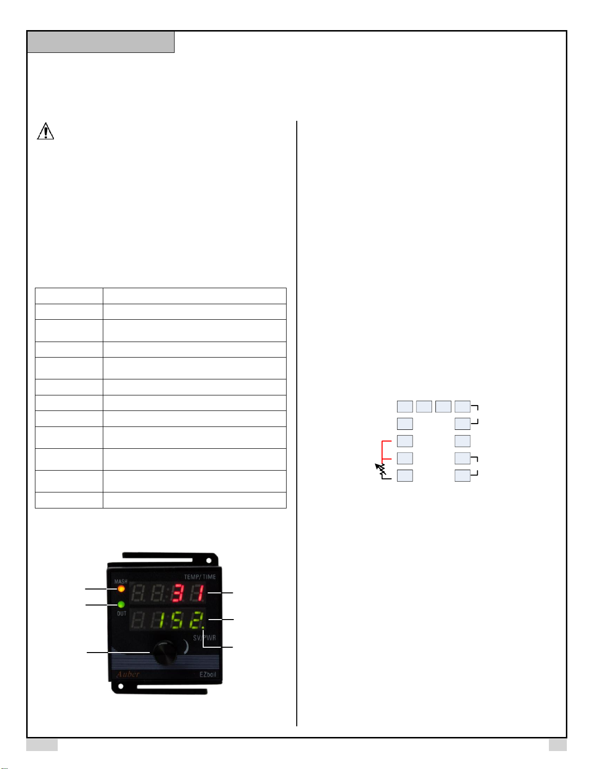
2. Front Panel
3
4
5
1
2
6
Figure 1. The front panel of EZboil
1). Top display. This display indicates the temperature sensor read out value.
When timer is activated, it will show time and temperature alternately.
2). Bottom display. In boiling mode, this display will show the percentage of
power being sent to the external SSR after the initial heat up phase. In mashing
control mode, this display will show the set temperature.
3). Rotary switch (knob). Turn it clockwise to increase the output power (or
selected parameter value); turn it counter-clockwise to reduce the output power
(or selected parameter value). Press it briefly to reset the timer (if enabled) and
to switch between mashing and boiling mode. Press and hold it for 5 seconds to
enter parameter settings menu. Please see section 6 for details.
4). Output indicator (OUT). This green LED light is synchronized with output. It
shows how much power the regulator is sending out (as a 12VDC control signal
pulse through terminal 6 and 7). When it is on solid, the output is 100% on. When
it is off, there should be no output. When it is flashing, the frequency of the
flashing is an indication of high or low power output. Higher frequency means
higher power output.
5). Mashing mode indicator (MASH). This yellow LED light indicates the
operation mode of the controller. When it is on, controller is in mashing mode;
when it is off, controller is in boiling mode.
6). Temperature setting adjusting indicator. This is the small dot at the lower
right corner. In mashing mode, when temperature set point is adjusted, it will
start to flash. It reminds you that you need to press the knob to confirm the
change. Otherwise, the temperature setting will return back in 2 seconds after
you stop the adjustment.
3. Wiring Terminals
The pin assignment of the back terminals of DSPR120 is shown in Figure 2.
1
2
3
13 14 6
7
8
9
10
4
5
AC
85~260V
SSR
+
-
RTD
R
R
W
Figure 2. Terminal assignments of DSPR120.
3.1 Sensor connection
DSPR120 only accepts Pt100 RTD temperature sensor. For a three-wire RTD
with standard DIN color code, the two red wires should be connected to the
terminals 3 and 4. The white wire should be connected to terminal 5. For a twowire RTD, the wires should be connected to terminals 4 and 5. Jump a wire
between terminals 3 and 4.
3.2 Power to the controller
The power cables should be connected to terminals 9 and 10. Polarity does not
matter. It can be powered by 85-260V AC power source. Neither a transformer
nor jumper is needed to wire it up. For the consistent with the wiring example
described later, we suggest you connect the hot wire to terminal 10 and neutral
to 9.
3.3 SSR output connection
The SSR control output of the DSPR110 provides a 12V DC signal that can
control up to 5 SSRs in parallel. Connect terminal 7 to the positive pole of the
SSR (terminal 3 on Auber’s SSRs). Connect terminal 6 to the negative pole of
the SSR (terminal 4 on Auber’s SSRs). Please make sure the SSR is installed
on the heat sink with proper current rating.
Instruction Manual
Page 2
AUBER INSTRUMENTS WWW.AUBERINS.COM
2017.03 P2/9
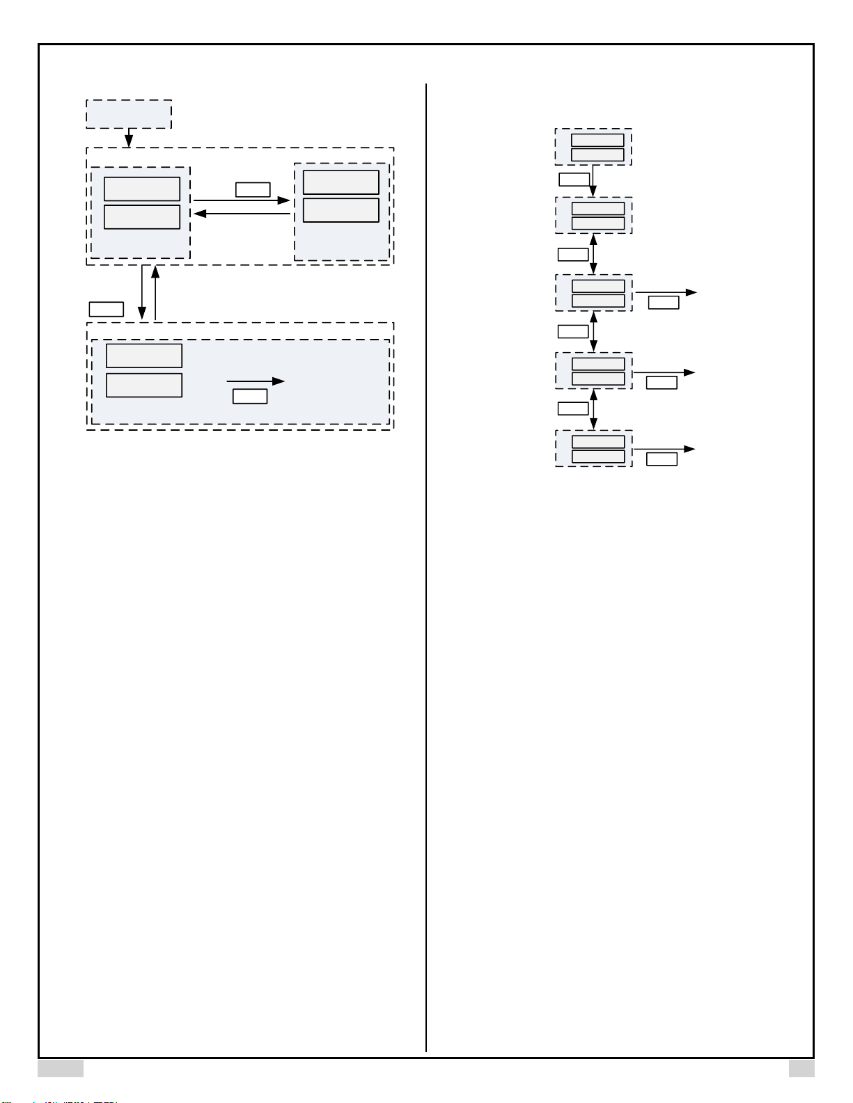
4. Display Status
Power on
80
100
Display mode 1
rst
n
Display mode 2
Mash
Parameter settings
Display mode 3
Next parameter
Goto
Timer reset /
mode selection
Knob
Press
Knob
Knob
Press down an d
Hold for 5s
Press
Exit
Exit
Figure 3. Display modes of DSPR120
Display mode 1 (Normal operating mode): When power is turned on, the top
display window shows the current sensor temperature reading. When timer is
activated, the top display will be switched between the current temperature and
current time alternately. In mashing mode, the bottom display will show your set
temperature. In boiling mode, the bottom display will show your current output
percentage (e.g. P50 for 50% power output). Please check section 5 for how to
adjust set temperature/power.
Display mode 2 (Timer reset & Operation mode selection): This display
mode allows you to reset the timer, or to switch between the mashing and boiling
operation mode.
A short press of the knob will enter this display mode.
1) The display will show “rSt” on top and “n” at the bottom. This is the exit menu.
If you enter this mode by accident, you can press the knob again to exit this
display mode without changing anything.
2) Rotate the dial clockwise for one click will change the bottom display to “y”.
This menu is to reset the timer. Press the knob will reset the timer. It has two
purposes. A) If you want to use the timer as regular timer without correlation to
the temperature, you can start the timer at any time by the reset button. B) After
timer is timed up and process ended, you can restart the process again by the
reset button instead of power off the system and power it on again.
3) Rotate the knob with two clicks, the top display will change to “Mode” and
bottom will show “Mash*”. Rotate the knob again, the bottom display will change
to “boil”. These two menus are for setting the controller to either mashing control
or boiling control mode. Press the knob will set the controller to the operation
mode displayed. Please check section 5.1 for details.
Display mode 3 (Parameter settings): Press down and hold the knob for 5
seconds to enter the display mode 3. Please check section 6 for details.
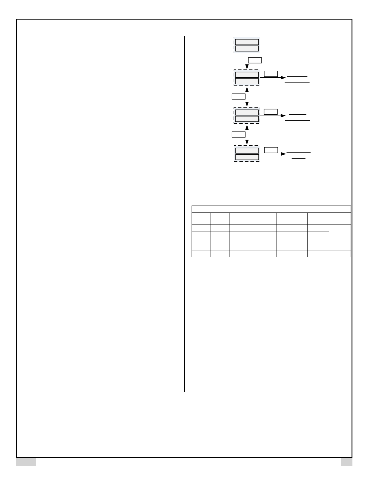
5. Operation
5.1 Operation mode selection
This controller offers two operation modes, mashing and boiling. When the
mashing mode is selected, the controller functions as a temperature controller.
It automatically adjusts the power output to hold the temperature at set point.
When boiling control mode is selected, the controller functions as a power
regulator. It allows the user to manually adjusting the power to control the
strength of the boil. Figure 4 shows how to select and switch between these two
modes.
rst
n
rst
y
80
100
Knob
Press
mode
mash
Rotate
mode
boil
Rotate
Knob
Mash Mode
Boil Mod e
Available if timer
is enabled
(TF =on)
Available if timer
is enabled
(TF =on)
Rotate
Knob
Knob
Press
Knob
Press
Knob
Timer Reset
Knob
Press
Figure 4. Flow chart for time reset & operation mode selection
Press the knob once. The display will show “rSt”. Rotate the knob with two clicks,
the top display will change to “Mode” and bottom will show “Mash*”. Press the
knob will set the controller to mashing mode. When mashing mode is selected,
the yellow indicator on the top left corner of the panel will lit. This indicator will
be off if the boiling mode is selected.
Note *: due to the limitation of 7 segment LED display, the letter “M” is displayed as “m”.
5.2 Mashing Operation
When first powered up, make sure the controller is in the mashing mode: The
yellow colored mashing mode indicator on the upper left corner should be on,
and the bottom display has no “P” on the left. If not, please change the control
mode to mashing mode as discussed in section 5.1 above. If you were using the
controller in the mashing mode when powered off last time, the controller will
start in mashing mode.
After controller is powered up, the top LED displays the current temperature
reading from the sensor. If temperature sensor is not connected, it will show
“orAL”. The bottom LED displays your set temperature. To adjust its value, just
rotate the knob. Once the value of the setting is changed, a small dot on the right
bottom corner will be flashing. It tells you that the setting has been changed but
not confirmed. After you adjust the temperature to the desired number, push the
knob to confirm the change. After confirmation, the new setting will remain on
the display and the dot will be turned off. If you forgot to push the dial, the display
will return to original set temperature after 2 seconds. The set point will remain
unchanged. This mechanism is for preventing temperature set point change by
accident.
The Output indicator will stay on solid right after powered up. This mean the
controller is heating up the kettle at maximum speed. Once the temperature is
getting close to the set point, the output indicator will start to flash at slower rate
or take a pause. It indicates the controller is trying to modulating the power to
hold the temperature stable.
For how to set up the timer in mashing mode, please read section 6.2.
Page 3
AUBER INSTRUMENTS WWW.AUBERINS.COM
2017.03 P3/9
5.3 Boiling Operation
When first powered up, make sure the controller is in the boiling mode: the
mashing mode indicator on the upper left corner is off and bottom display has a
“P” on the left. If not, change the control mode to boiling mode as discussed in
section 5.1 above. If you were using the controller in the boiling mode when
powered off last time, the controller will start in boiling mode.
The top LED displays the current temperature reading from the sensor. If
temperature sensor is not connected, it will show orAL. The controller will not
turn on the heater if the sensor is not connected. The bottom LED displays the
boiling output in percentage of the power. For example, if you use a 5500
Watts heater, “P50” mean the heater is running at 50% of power, or 2750
Watts (5500x50%=2750). The symbol “P” on the left is for making sure that the
display does not get confused with temperature setting of the mashing mode.
You can rotate the knob to adjust the output value. The new setting will take
effect automatically. There is no need to push the knob to confirm as the
temperature setting change in the mashing mode. For the first time use, while
the controller is still in the acceleration phase, you should set the boiling output
to a value below 60%. Once the controller finished the acceleration, it will
switch to this power level automatically. After getting familiar with your system,
you can set to a higher value that produce a rolling boil without boiling over.
When the controller is powered up, the output indicator will stay on solid. This
mean the controller is in the acceleration phase. Once the temperature rise
above the acceleration phase, the power output will be reduced to the value as
shown on the bottom display. The Output indicator will start to flash at slower
rate.
Note, when adjusting the boiling output setting while the controller is still in the
acceleration phase, the new setting will be shown on the bottom display.
However, it will not take effect until the acceleration phase is finished. If you want
to manually control the power output during the entire boiling process, set bAST
to zero (see section 6.3 for details).
For how to set up the boiling mode, please read section 6.3.
6. Control Parameters
Parameters are divided into three groups (figure 5): MASH for mashing control,
BOIL for boiling control, and SYST for system configuration. The same type of
parameter may have slightly different names when used in different mode. For
example, the timer setting in mashing mode is called “t”, while this parameter is
called “bt” in the boiling mode.
To enter parameter setting mode, press and hold the knob for at least 5s. Then
you will see “GOTO” on the top display. Rotate the knob, you will see the bottom
display changes with three different names: MASH (for mashing parameters,
figure 7), BOIL (for boiling parameters, figure 8) and SYST (for system settings,
figure 6). The parameter values are stored in the controller memory. All the
settings remain unchanged if you power it off.
Push the dial to enter the selected parameter group. Then top display shows the
current selected parameter name, and the bottom display shows its
value/options. Rotate the knob clockwise to increase the value, and rotate it
counter-clockwise to reduce the value. Faster rotating speed will change the
value rapidly. Once finished, press knob again to confirm and go to next
parameter. You can press the knob repeatedly to exit the setting quickly.
Press down
and hold the
knob for 5s
80
100
Knob
goto
mash
goto
boil
goto
syst
Enter Mash
mode settings
Enter Boil
mode settings
Enter System
settings
Knob
Press
Knob
Press
Rotate
Knob
Rotate
Knob
Knob
Press
Figure 5. Parameter group selection
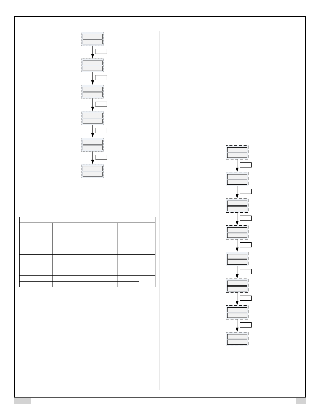
6.1 System settings
Parameters that are shared by both control modes are under this group.
Table 1. System configuration parameters
System Configuration
Display
Code
Description
Setting
Range
Initial
Setting
Remark
tF
tF
Timer function
ON, OFF
ON
Note 1
tdIr
tdIr
Timer counting direction
dn, uP
dn
Pb
Pb
Temperature reading
offset
-100~+100 ° C
or ° F
0
Note 2
C-F
C-F
Temp. display unit
° C, °F
°F
Note 3
Note 1. Timer settings. tF, tdIr
tF: The timer function is controlled by a master parameter tF. When it is set to
ON, the timer function (for both mashing and boiling modes) is enabled. When
tF is set to OFF, the timer function is disabled.
tdIr: Timer direction parameter. Set it to up for timer counting up and dn for timer
counting down.
Note 2. Input offset. Pb
Pb is used to set an input offset to compensate the error produced by the sensor
or input signal itself. For example, if the controller displays 2ºC when probe is in
ice/water mixture, setting Pb = -2, will make the controller display 0ºC.
Note 3. Temperature unit setting. C-F
C-F determines the temperature unit. It can be set to C (Celsius, ˚C) or F
(Fahrenheit, ˚F).
Page 4
AUBER INSTRUMENTS WWW.AUBERINS.COM
2017.03 P4/9
goto
syst
Knob
tf
on
Knob
tdir
dn
Knob
pb
0
Knob
C-f
f
Knob
80
100
Timer function
Timer
counting
direction
Temperature
reading offset
Temp. display
unit
Press
Press
Press
Press
Press
End
Figure 6. Flow chart of setting system parameters
6.2 Mashing Parameters
Table 2. Mashing parameters
Mashing Mode Parameters
Display
Code
Description
Setting Range
Initial
Setting
Remark t t
Mashing time set
value
00:00~99:99
(hour: minute)
1:00
Note 5
tSP
tSP
Mashing timer start
temp.
-999~+9999 ° C
or ° F
151
ALH
ALH
Mashing alarm set
temp.
-999~+9999 ° C
or ° F
150
Note 6
EO
EO
Mashing ending
options
ON, OFF
OFF
Note 5
oScr
oScr
Overshoot correction
-100~+100
0
Note 7
AttE
AttE
Attenuation constant
-2~+2
0
Note 5. Timer Function: t, tSP, EO
This timer function allows the controller to show the mashing time. It makes a
beeping sound when timed out and will display the process is ended. It can also
automatically shut off the controller’s power output after time out. The time
duration is set by the t parameter for mashing mode. The unit is hour: minutes.
When timer function is enabled, the timer counting will be started by timer start
temperature, tSP. When temperature reaches timer start temperature, the timer
starts to count. After timer started counting, it will continue even if the
temperature drops below this start temperature. The timer can be reset to start
from beginning again. To reset the timer, press the knob momentarily, the display
will show rSt on top and “n” at the bottom, rotate the dial clockwise will change
the bottom display to “y”. Press the knob again will reset the timer (Figure 4)
After the timer starts, the top display will be switched between the current
temperature and current time alternately in every 6 seconds. The temperature
and time display can be easily differentiated with their appearance. The
temperature reading has two or three digits. For example, 212 degrees will be
displayed as “212”. The timer display has four digits with flashing colon in the
middle. For example, “01:20” for 1 hour 20 minutes.
When time counting ends, the controller will generate six long beeps. The top
display will switch between the current temperature and “End” alternately. After
timer ends, the power output can be configured either to continue heating, or
shut off. It is controlled by the parameter called ending options, EO. Set it to
ON for continue heating, set it to OFF to turn off the output.
If you want to use the timer as a regular timer without correlating to the
temperature setting, you can set the tSP below the ambient temperature (or
zero). The timer will start as soon as the regulator is powered up. You can use
the reset button (rSt) to reset the timer at any time.
Note 6. Alarm Function: ALH
EZboil has a built-in buzzer that can be programmed to beep when temperature
reaches the alarm set temperature, ALH. The alarm will generate four short
beeps every time the temperature rise from below ALH to higher than ALH. The
alarm function can be used to notify the operator when temperature is approach
the boil. The alarm function does not affect the heating or the time function, it
only provides the alarm sound.
goto
mash
Knob
t
1:00
Knob
Tsp[
151
Knob
alh
150
Knob
eo
off
Knob
oscr
0
Knob
atte
0
Knob
80
100
Press
Press
Press
Press
Press
Press
Press
Mashing time
set value
Mashing timer
start temp.
Mashing alarm
set temp.
Mashing ending
options
Overshoot
correction
Attenuation
constant
End
Figure 7. Flow chart of setting mashing parameters
Note 7. Temperature Control Tuning Parameters: oScr, AttE
The mashing control mode utilizes AI algorithm instead of the commonly used
PID or On/off control algorithm. The program is optimized for beer mashing. For
most system, there is no need to tune. It allows the system to heat up at
maximum speed, then hold the temperature stable with one-degree precision. If
Page 5

AUBER INSTRUMENTS WWW.AUBERINS.COM
2017.03 P5/9
you are not satisfied with the control result, these two parameters will help you
to fine tune the system. The overshot correction, oScr is for adjusting the
temperature overshot during the initial heat up. For example, if the temperature
overshot 3 degrees, set oScr = 3 should remove the overshoot. This parameter
has no effect after the temperature reach the set point. The attenuation
constant, AttE is for adjusting the temperature stability during mashing. The
value is from -2 to +2. The default value is 0. If the temperature fluctuates more
than one degree, user can increase the value. If the controller takes too much
time to correct the temperature drop, user can reduce the AttE to make the
system more responsive.
6.3 Boiling Parameters
For the easy of discussion, we divide the boiling mode into two phases, the initial
heating phase and boiling phase. During the initial heating phase, power
output is set high to accelerate the temperature rise. During the boiling phase,
the power output is lowered to prevent the boiling over. We name the output
setting for the boiling phase as “Boil Output” setting. Its value is always
displayed on the bottom LED display and can be adjusted by turning the knob.
The acceleration power output setting is not displayed at bottom display during
initial heating, because it rarely set to less than 100%.
Table 3. Boiling parameters
Boiling Mode Parameters
Display
Code
Description
Setting Range
Initial
Setting
Remark
bAST
bAST
Boiling acceleration
set temp.
-999~+9999 ° C
or ° F
200
Note 8
bOUT
bOUT
Boiling acceleration
output power
0~100%
100
bt
bt
Boiling time set value
00:00~99:99
(hour: minute)
1:00
Note 9
btSP
btSP
Boiling timer start
temp.
-999~+9999 ° C
or ° F
208
bALH
bALH
Boiling alarm set
temp.
-999~+9999 ° C
or ° F
200
Note 10
bEO
bEO
Boiling ending
options
ON, OFF
OFF
Note 9
Note 8. Acceleration heating function: bAST, bOUT
EZboil accelerates heating speed of the initial heating phase by running the
heater at high power, then reduce the power once the temperature is getting
close to the boil. The heating acceleration is controlled by two parameters,
Boiling acceleration set temperature, bAST and Boiling acceleration output
power, bOUT. The bAST set the temperature limit that below this temperature,
the controller will output at a power determined by the bOUT. When temperature
rise to the bAST, the output will automatically reduce to a lower level to prevent
a messy boiling over. The boiling over is caused by several factors including the
amount of foam on the surface and the power of the heater. The more foams
there is, the easier it is to boil over. The vigorous the boil is, the easy it is to boil
over. To preventing the boiling over, operator should skim the foam out and
reduce the power as the temperature approaching the boiling. Since the heater
power and liquid volume varies between each application, we suggest the bAST
to be set at least 5 degree (Fahrenheit) below the boiling point for the first time
use. As you getting familiar with your system, you can change this setting to
higher or lower. The bOUT is the power used during initial heating phase. The
unit is in percent of power. It should be set to 100% unless you have a very
powerful heater with very small amount of liquid. The bOUT setting does not limit
the power regulation range for boiling phase. If you don’t need to use this
feature, set bAST to 0, so this controller will work as a manual mode
controller over the entire temperature range.
Note 9. Timer Function: bt, btSP, bEO
This timer function allows the controller to show the boiling time. It makes a
beeping sound when timed out and will display the process is ended. It can also
automatically shut off the controller’s power output after time out. The time
duration is set by bt parameter for boiling mode. The unit is hour: minutes.
When timer function is enabled, the timer counting will be started by timer start
temperature, btSP. When temperature reaches timer start temperature, the
timer starts to count. After timer started counting, it will continue even if the
temperature drops below this start temperature. The timer can be reset to start
from beginning again. To reset the timer, press the knob momentarily, the display
will show rSt on top and “n” at the bottom, rotate the dial clockwise will change
the bottom display to “y”. Press the dial again will reset the timer (Figure 4)
After the timer starts, the top display will be switched between the current
temperature and current time alternately in every 6 seconds. The temperature
and time display can be easily differentiated with their appearance. The
temperature reading has two or three digits. For example, 212 degrees will be
displayed as “212”. The timer display has four digits with flashing colon in the
middle. For example, “01:20” for 1 hour 20 minutes.
When time counting ends, the controller will generate six long beeps. The top
display will switch between the current temperature and “End” alternately. After
timer ends, the power output can be configured either to continue heating, or
shut off. It is controlled by the parameter called ending options, bEO. Set it to
ON for continue heating, set it to OFF to turn off the output.
goto
boil
Knob
bast
200
Knob
bout
100
Knob
bt
1:00
Knob
btsp
208
Knob
balh
200
Knob
beo
off
Knob
Press
Press
Press
Press
Press
Press
Press
Boil acceleration
set temp.
Boil
acceleration
output power
Boil time set
value
Boil timer
start temp.
Boil alarm
set temp.
Boil ending
options
80
100
End
Figure 8. Flow chart of setting boiling parameters
If you want to use the timer as a regular timer without correlating to the
temperature setting, you can set btSP below the ambient temperature (or just
zero). The timer will start as soon as the regulator is powered up. You can use
the reset button (rSt) to reset the timer at any time.
Page 6
AUBER INSTRUMENTS WWW.AUBERINS.COM
2017.03 P6/9
Note 10. Alarm Function: bALH
EZboil has a built-in buzzer that can be programmed to beep when temperature
reaches the alarm set temperature, bALH. The alarm will generate four short
beeps every time the temperature rise from below ALH to higher than ALH. The
alarm function can be used to notify the operator when temperature is
approaching the boil. The alarm function does not affect the heating or the time
function, it only provides the alarm sound.
7. Application examples:
1. Timer operation example:
The timer can be used for several ways to help the boiling process.
1) Use it to automatically control the boiling time (boiling mode).
Set the parameter as following
tF=on, btSP=210, tdIr=dn, bEO=OFF, bt=1:30,
The timer will start to count when temperature reaches 210 degrees. The timer
will count down from 1:30, when time out, the controller will stop heating, beeps,
and flash “End”.
2) Use the timer as a regular timer (boiling mode).
Set btSP below the ambient temperature so that timer is available, set bt to a
very long time so that it will not end before operator decide to end the boil. The
counting direction should be up. Use the reset button (rSt) to reset the timer at
any time
tF=on, btSP=50, tdIr=up, bEO=on, bt=60:00.
3) Use the timer as a regular timer (mashing mode).
Set tSP below the ambient temperature so that timer is available, set t to a very
long time so that it will not end before operator decide to end the mash. The
counting direction should be up. Use the reset button (rSt) to reset the timer at
any time
tF=on, tSP=50, tdIr=up, EO=on, t=60:00.
4) Use EZboil as a manual regulator (similar to DSPR1)
To use it as manual regulator with temperature reading, please set it to boiling
mode. Disable timer, and set boiling acceleration set temperature below ambient
temperature (or just zero).
Mode=boiling, tF=off, bAST=0
8. Wiring Examples
Example 1. Here are two wiring diagrams of how to connect a DC triggered AC
SSR with this power regulator.
1
2
3
13 14 6
7
8
9
10
4
5
RTD
R
R
W
-
+
34
120V AC
L
N
Heater
+
-
SSR
1
2
3
13 14 6
7
8
9
10
4
5
RTD
R
R
W
Heater
240V AC
L1
L2
-
+
34
+
-
SSR
Figure 9. Wiring examples of controlling a heater with SSR and DSPR120 in a
120VAC system (upper) and in a 240VAC system (lower).
9. Common sensor errors:
This regulator will display error message or incorrect temperature reading if your
sensor is not connected, or your sensor is bad. Top display will flash “orAL” and
“932” alternately, if you set it to Fahrenheit display (C-F = ° F); or “orAL” and “500”
alternately, if you set it to Celsius display (C-F = ° C).
Auber Instruments
5755 North Point Parkway, Suite 99
Alpharetta, GA 30022
www.auberins.com
Email: info@auberins.com Tel: 770-569-8420
Copyright 2007-2017, Auber Instruments All Rights Reserved.
No part of this manual shall be copied, reproduced, or transmitted in any way
without the prior, written consent of Auber Instruments. Auber Instruments
retains the exclusive rights to all information included in this document.
Page 7
AUBER INSTRUMENTS WWW.AUBERINS.COM
2017.03 P7/9
Appendix
Technical Talk -- How does it Work? v1.1
There are three commonly used methods for AC power control.
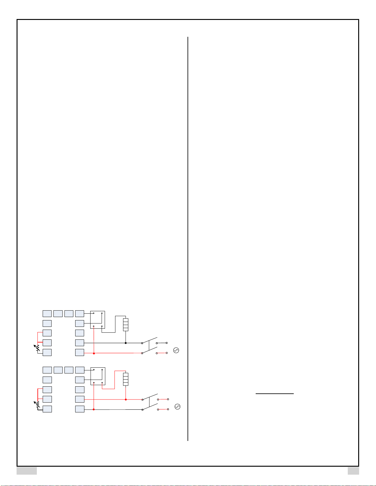
1) Phase angle firing. In this method, the AC power control is achieved by firing the SCR at different phase angle. This is how our SSVR works. This method offer the
most uniform power output. But the output is very difficult to be adjusted linearly due to the shape of the sine wave. Because of the sharp cut off, there is a potential
electromagnetic interference (EMI or RFI) if there are inductive devices on the power line. Some of the inductive devices cannot be controlled by this method.
Figure 4. SSVR and TRIAC use phase-angle firing to regulate the power.
Figure 5. Original AC sine wave is overlaid with SSVR output wave form. The blue colored area shows the power output that has been blocked.
2) Time proportional firing. A fixed cycle time needs to be defined in this method. Then, the controller or regulator adjusts the on time during each cycle to achieve
the power control. For example, if the cycle time is 1 second, turn on the power for 0.25 second for every 1 second means a 25% power output. Most of PID controllers
use this method to control SSRs. This is also how the manual mode of Auber's PID controller works, except the cycle time has to be 2 second or longer.
Using this method, the user can linearly adjust output. But the power output is pulsed at each cycle. The shortest cycle time for most PID is either 1 or 2 second.
Therefore, power is pulsed at 1 or 2 seconds. When heating a liquid, heat is not transferred as smooth as the phase-angle fire method.
Page 8
AUBER INSTRUMENTS WWW.AUBERINS.COM
2017.03 P8/9
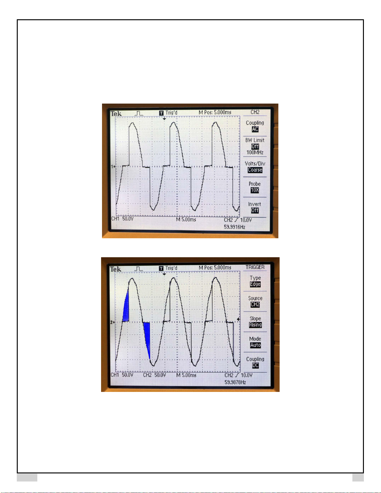
Figure 6. A 25% output control signal from a PID controller in the time proportional firing mode. Cycle time is 1 second. The output signal is 250 millisecond (ms) on,
and 750 ms off during each cycle period.
Figure 7. The control signal and SSR output waveform overlaid. When the DC signal (Channel 2, square wave) is on, the AC power can go through (Channel 1).
When the DC signal drop to zero, the AC power is blocked.
3) Burst firing. This method is similar to time proportional firing (section 2). But in contrast to the time proportional mode, where the SSR is fired once for each fixed
cycle period (which are usually 2 seconds or longer), the regulator will find the minimum cycle time to achieve the desired output percentage. The on pulse can be as
short as one AC cycle. So power is distributed more evenly over cycle time. This leads to of a more uniform power output. Several PID controllers on the market use
this mode. Our DSPR also uses this approach as the default mode to regulate power.
Page 9
AUBER INSTRUMENTS WWW.AUBERINS.COM
2017.03 P9/9
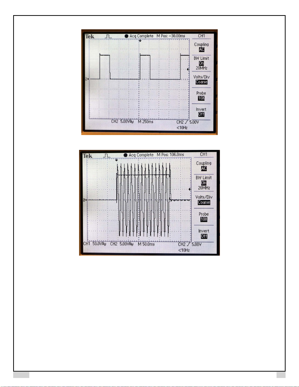
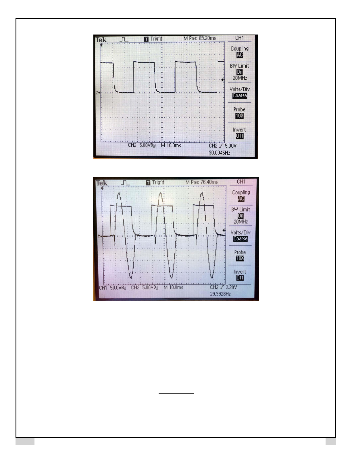
Figure 8. A 50% output control signal from DSPR when it is operating in the bust firing mode. Each pulse is 16.67 ms long, which is the same as a 60 Hz AC cycle.
So one pulse on and one pulse cycle off is equal to 50% output.
Figure 9. The DSPR control signal and SSR output waveform overlaid. The DSPR detects the frequency and phase of the AC power line, so that the pulse width and
firing time is synchronized with AC cycle.
Auber Instruments
5755 North Point Parkway, Suite 99
Alpharetta, GA 30022
www.auberins.com
Email: info@auberins.com Tel: 770-569-8420
Copyright 2007-2017, Auber Instruments All Rights Reserved.
No part of this manual shall be copied, reproduced, or transmitted in any way without the prior, written consent of Auber Instruments. Auber Instruments retains the
exclusive rights to all information included in this document.
 Loading...