

Page 1
AUBER INSTRUMENTS WWW.AUBERINS.COM
2017.10 P1/4
ECT-100 Temperature Controller
Version 1.4 (Oct, 2017)
1. Overview
This is an economical plug-n-play controller that can be used for Sous Vide
cooking, and other low temperature control applications (<221° F or 105°C). It
offers PID mode for heating control, as well as on/off control mode for either
heating or cooling. The PID mode is suitable for precision temperature control
such as Sous Vide cooking. The on/off control is suited for controlling devices
that does not like to be switched on/off too frequently such as the compressor
of the refrigerator.
This controller has a temperature sensor comes with it, which can measure
temperature in the range of -50 ~ 120°C (-58 ~ 248°F). The power input can be
either 120V AC or 240V AC. The output power will be supplied to the output
socket, to which a load can be plugged. The output power is controlled by an
internal electromechanical relay whose action synchronize with the OUT
indicator on the front panel. The output voltage is the same as the input voltage.
2. Specification
Temperature control range
-50 ~ 105° C, -58 ~ 221°F
Temperature resolution
1° C (between -50 ~ 120° C)
1° F (between -58 ~ 248°F)
Temperature accuracy
0.5 ° C or 0.9 °F
Control mode
On/off (heating or cooling), PID (heating)
Control output
12A at 120VAC, 10A at 240VAC
Operating input voltage
85 ~ 240V AC, 50/60Hz
Audio Alarm
High and low limit
Sensor type
Silicon band gap sensor
Sensor size
0.25” OD (6.35 mm) x 1" length (25 mm)
Sensor connection
3-pin connector
Sensor cable length
6 ft (2 m)
Dimension
3.4’’ x1.7’’ x 4.7’’ (85 x 47 x 118 mm)
Ambient temperature
-20 ~ 50° C (0°F ~ 120° F)
Power cable length
3 ft (1 m)
Warranty
One (1) year
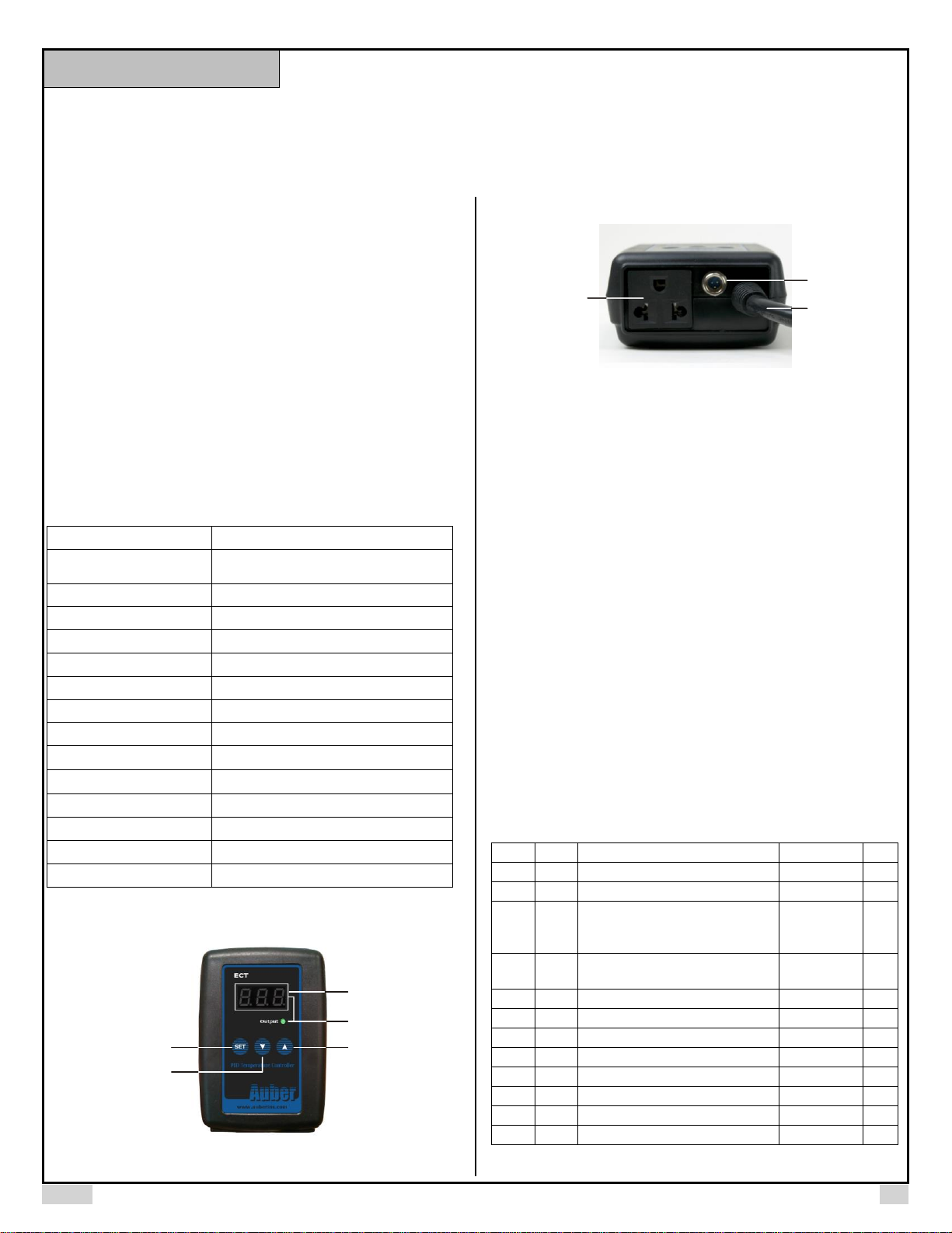
3. Front Panel and Connectors
①
②
③
④
⑤
Figure 1. Front Panel.
⑥
⑦
⑧
Figure 2. Bottom Panel
① Set Key
② Down Key
③ Up Key/Mute
④ Output Indicator
⑤ Temperature Display
⑥ Power Output Socket
⑦ Power Input
⑧ Sensor Input
4. Temperature Setup
To change its preset temperature: Press SET key once to switch the display
from actual temperature to set temperature. The display will start to blink.
Press Up and Down keys to increase or decrease the setting temperature.
When finished, press SET key once to confirm and exit.
Note: Parameter remains unchanged unless you press set key to confirm.
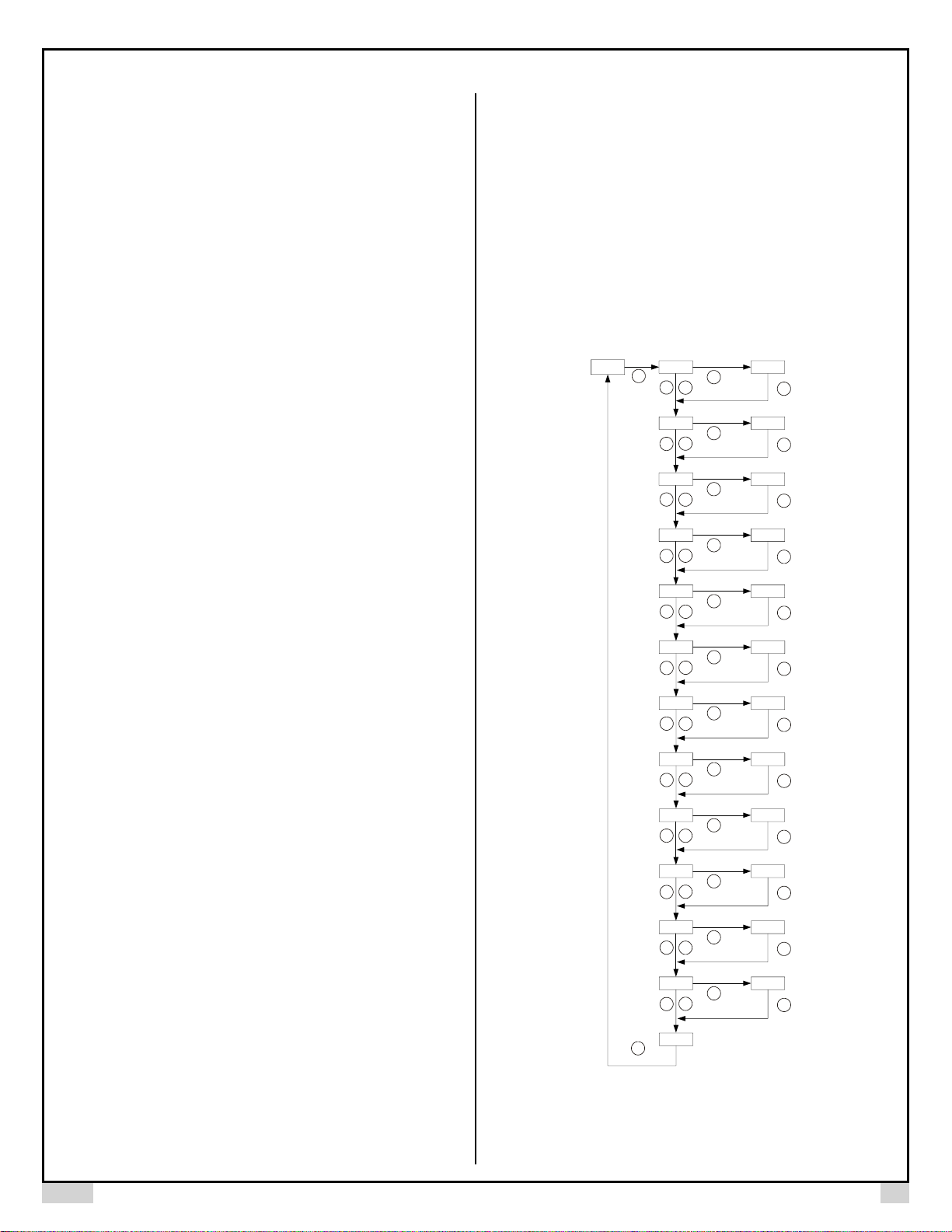
5. Parameter Setup
To enter parameter setting mode, press and hold SET key for 6s and it will
show “AH” in the display window. Please see Table 1 for all parameters.
Please refer to the flow chart in Figure 1 for how to change parameters.
Table 1. Parameter Settings and its initials.
Symbol
Display
Description
Range
Initial
AH
AH
High Limit Alarm
-99-999
210
AL
AL
Low Limit Alarm
-99-999
32
Mod
MND
Control mode
PID
HEA (heating)
COL (cooling)
PID
AS
AS
Anti-short cycle delay
(only valid for cooling mode)
0-200
6
Hy
Hy
Hysteresis band
0-999
3 P p
Proportional band (in 1 degree)
0-999
18 I I
Integral constant (second)
0-999
650 d d
Derivative constant (second)
0-999
40 t T
Cycle rate (second)
0-999
20
AT
AT
Auto-tune
0=off, 1=on
0
C-F
C-F
Temperature unit
° C or °F
°F
oFS
Ofs
Input offset
-99-99
0
Instruction Manual
Page 2
AUBER INSTRUMENTS WWW.AUBERINS.COM
2017.10 P2/3
Details about each parameter
• AH. High limit alarm. When process temperature is higher than AH, the
internal audio buzzer will be energized. For example, if AH set to 290, the
buzzer will be on at 291 and off at 290. When the buzzer is on, the
display window will be flashing between “A-H” and the current process
temperature. Press Up key to mute the alarm.
• AL. Low limit alarm. When process temperature is lower than AL, the
internal audio buzzer will be energized. For example, if AL is set to 100.
The buzzer will be on when temperature drop to 99. It will be turned off
when temperature rise above 100. The low limit alarm is suppressed at
powering up. It will be reactivated once the temperature has reached set
point. When the buzzer is on, the display window will be flashing between
“A-L” and the current temperature. Press Up key to mute the alarm.
• Mod. Control mode. Three control modes are available: PID (PID mode
for heating), HEA (on/off mode for heating), and COL (on/off mode for
cooling).
• AS. Anti-short cycle delay. This is the delay time to turn on the cooler
(e.g., refrigerator). If the cooler is compressor based, compressor should
not be turned on immediately when it is at high pressure (just after turned
off). Otherwise, it may shorten the life of compressor. The anti-short cycle
delay function can be used to prevent the rapid cycling of the compressor.
It establishes the minimum time that the compressor remains off (after
reaching cutout) before turns on again. The delay overrides any controller
demand and does not allow the compressor to turn on until the set delaytime has elapsed. It gives time to release the refrigerant pressure through
evaporator. It typically set to 6 (minutes). The unit is in minutes. This
setting is only valid for cooling mode.
• Hy. Hysteresis band (or dead band). This parameter is valid only for
on/off control mode (heating or cooling). In the on/off heating mode, the
controller will stop sending power to the heater when temperature T is
above the set value (SV), and start sending power again to the heater if T
drops below (SV-Hy). For example, if SV=100 ° C. Hy=3 ° C, the heater
will be turned off when the temperature rises above 100 ° C; it will be
turned on again as the temperature drops below 97 ° C. For the on/off
cooling mode, the compressor will be turned off when T<SV. It will be
turned on again when T>SV+Hy.
• P. Proportional band. The unit is 1 degree. This parameter controls the
output level based on the difference between the process temperature
and set temperature. The greater P value, the weaker the action (lower
gain). If P=7, the proportional band is 7 degree. When the sensor
temperature is 7 degrees below the proportional band (10 degrees below
the setting), the controller will have 100% output. When the temperature
is 5 degree below the set point, the output is 71%. When the temperature
is equal to the setting, the controller will have 0% output (assuming
integral and derivative functions are turned off). This constant also affects
both integral and derivative action. Smaller P values will make the both
integral and derivative action stronger. Please note the value of the P is
temperature unit sensitive. If you found an optimized P value when
operating the controller in Fahrenheit, you need to divide the P by 1.8
when changing the temperature unit to Celsius.
• I. Integral time. The unit is in seconds. This parameter controls the output
of controller based on the difference between the measured and set
temperature integrated with time. Integral action is used to eliminate
temperature offset. Larger number means slower action. e. g. assuming
the difference between the measured and set temperature is 2 degrees
and remain unchanged, the output will increase continuously with time
until it reaches 100%. When temperature fluctuate regularly (system
oscillating), increase the integral time. Decrease it if the controller is
taking too long to eliminate the temperature offset. When I=0, the system
becomes a PD controller. For very slow response system such as slow
cooker and large commercial rice cooker, set I = 0 will significantly reduce
the temperature overshoot.
• d. Derivative time. The unit is in seconds. Derivative action contributes
the output power based on the rate of temperature change. Derivative
action can be used to minimize the temperature overshoot by responding
its rate of change. The larger the number is, the faster the action will be.
For example, when there is a disturbance causing the temperature
dropping at a very high rate, the derivative action can change the
controller output based on the rate of change rather than the net amount
of change. This will allow the controller to act sooner. It will turn the
heater to full power before the temperature drops too much.
• t. Cycle rate. The unit is in seconds. This unit determines how long for the
controller to calculate each action. For example, if T is set to 20 seconds,
when the controller decides the output should be 10%, it will turn on the
heater 2 second for every 20 seconds. This parameter should set at 20
seconds for the internal mechanical relay. This setting is also
recommended for controlling a solenoid valve or a compressor of
refrigerator to reduce the frequency of on/off.
Push down
for 6s
74 ah 200
SET
SET
SET
^
V
al 20
SET
SET
V
^
mod P/d
SET
SET
^
V
as 6
SET
SET
V
^
hy 3
SET
SET
^
V
p 18
SET
SET
V
^
i 645
SET
SET
^
V
d 40
SET
SET
V
^
t 20
SET
SET
^
V
at 0
SET
SET
V
^
C-f
O
F
SET
SET
^
V
ofs 0
SET
SET
V
^
end
SET
Figure 1. Flow chart of setting up parameters.
Page 3

AUBER INSTRUMENTS WWW.AUBERINS.COM
2017.10 P3/3
• AT. Auto-tune function. Set AT to 1 then exit the menu. The display will
start to flash alternately between AT and the current temperature, which
indicates auto-tuning is in progress. When the display stops flashing, the
auto-tuning is finished. Now, the newly calculated PID parameters are set
and are used for the system. The new parameters will store in the
memory even the power is off
• C-F. Temperature display unit. You can set the unit either to Celsius or
Fahrenheit.
• oFS. Input Offset. oFS is used to compensate the error produced by the
sensor or input signal itself. For example, if the unit displays 37 degree
when the actual temperature is 32, set parameter oFS = - 5 will make the
controller display 32 degree. The displayed process temperature = actual
measured temperature + oFS.
6. Recommended Parameter for Sous Vide Cooking
The default setting: P=18, I=650, d=40, and t=20 is optimized for Sous Vide
cooking with rice cooker or steam table.
7. Connecting the Sensor to the Controller
The connector of sensor contains a slot for fitting pin connection. It also has a
spring lock to prevent disconnections from accidental pulling on the cable. To
install the to the unit, please align the slot of the female connector on the
sensor to the red mark of the male connector on the unit, then hold the tail and
push the female connector forward. To remove the connector, please pull the
spring-loaded collar of the female connector. Please see the Figure 3 and
Figure 4 below for details.
Figure 3. Install the Sensor.
Figure 4. Remove the Sensor.
Auber Instruments Inc.
5755 North Point Parkway, Suite 99,
Alpharetta, GA 30022
www.auberins.com
E-mail: info@auberins.com Tel: 770-569-8420
Copyright 2007-2017, Auber Instruments All Rights Reserved.
No part of this manual shall be copied, reproduced, or transmitted in any way without the
prior, written consent of Auber Instruments. Auber Instruments retains the exclusive
rights to all information included in this document.
 Loading...