

Page 1
AUBER INSTRUMENTS WWW.AUBERINS.COM
Instruction Manual
AT210 Wireless Digital Thermometer
Version 1.0 (January, 2014)
1. Features
The AT210 wireless digital thermometer can be used for remote temperature
monitoring. It consists of two units: AT210-A (slave unit) and AT210-B (master unit).
The slave unit connects to the temperature sensor and displays measured value. It
also sends the measured temperature reading to the master unit and allow remote
monitoring and remote parameter setting through wireless connections. The master
unit can communicate with up to 10 slave units. The AT210 thermometer have two
alarm settings for a built-in buzzer. One can be used for high limit alarm and the other
can be used for low fuel (limit) alarm. This thermometer can also store the highest
temperature reading with a time stamp during the temperature monitoring process. The
slave unit has a 12VDC 2.5mm power output that is synchronized with the build-in
alarm buzzer, which can be used to drive an external buzzer or other devices. Both
units are powered by 12VDC through an 2.1mm AC adapter for continuous operation. It
can also be powered by a car battery directly.
2. Specifications
◆
Power input: 12VDC (2.1mm OD connector)
◆
AC adaptor: 100-240V, 50/60Hz input. 12 VDC, 1 Amp output.
◆
Power consumption: <0.5W
◆
Sampling rate: 2 samples/second
◆
Accuracy: 0.2% full scale
◆
Thermometer reading range: -320-2300°F (-200~1300°C).
◆
Power output (on slave unit): 12VDC (2.5mm OD connector), 1 Amp, synchronized
with the internal buzzer.
◆
LED display: 0.39'’, red
◆
Internal buzzer: two alarms (high limit or low limit alarm).
◆
Dimension: 2.8x3.5x1.2" (70x90x30mm)
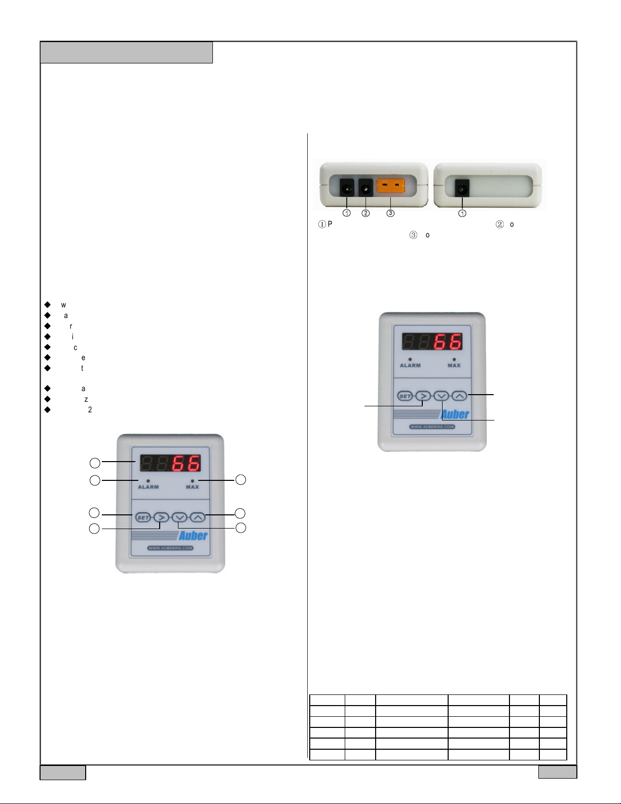
3. Front Panel
①
Power Input - 12VDC power supply input (2.1 mm O.D.). ②Power Output -
12VDC output (2.5 mm O.D.). ③Probe Input - temperature probe input.
Figure 2. Bottom view of AT210-A (left, slave unit) and AT210-B (right, master unit).
5. Key functions during temperature monitoring
During the normal temperature monitoring mode, you can mute the alarm, check the
peak value, and change display brightness with the keys on the front panel (Figure 3).
3. Switch display
between bright and
1. Temporarily
mute the alarm
dimmed.
2. Check peak value
1
2
4
5
Figure 1. Front panel of AT210-A and B.
1. Digital display window.
2. Alarm indicator: blinking when alarm is triggered.
3. Peak value indicator: stay solid on when peak value is displayed; blinking when the
time stamp of the peak value is displayed.
4. Set key: enter code; confirm input value.
5. Shift key: shift digit; mute the alarm buzzer.
6. Down key: change digit value; move to the previous parameter; display peak
temperature and the time when peak temperature is reached/ reset peak values.
7. Up key: change digit value / move to next parameter / change brightness.
3
7
6
4. Connectors on the meter
The connectors on the meter are shown in Figure 2. Connecting the 12V DC power
adapter to the connector 1 from wall outlet. Connecting the external buzzer to
connector 2. The polarity for this socket is center pin positive (+), outer collar negative
(−). Connect the K thermocouple to terminal 3. Please note that thermocouple
connector also has polarity. The wide blade should go to the wide slot.
Figure 3. Operating keys on AT210-A and B.
Key Function Descriptions:
1. Temporarily mute the alarm. When the temperature reaches the alarm
temperature, the alarm indicator will flash and meter will start beeping. Press Shift key
once can temporarily mute the alarm. Alarm will be triggered again if the alarm set
temperature is reached again. Please see Section 6 for detailed explanation alarm
settings.
2. Check the peak value. Press Down key once to show peak temperature, and the
MAX LED will light up; press Down key again to show the time stamp, i.e., the time
when peak temperature is reached (count from the start of the timer, unit is seconds),
and the MAX LED will flash. If the temperature continues rising, a new peak
temperature and its time will be written to the memory to replace the previous peak
value. Please see Section 9 for details.
3. Dimmer the display brightness. Press Up key to toggle the display brightness
between the dimmed display and the normal bright display. The brightness of the
dimmed display is determined by the parameter “brit” described in the later section of
the manual (see Section 7).
6. Alarm setting (code 0001)
The meter has two programmable alarms that can be set to turn on the buzzer at
specified temperatures. The alarm1 is controlled by parameters AH1 and AL1; the
alarm2 is controlled by AH2 and AL2. These parameters can be accessed by code 0001
(see Table 1).
Table 1. Alarm parameters.
Symbol Name Description Setting Range Initial Note
AH1 AH1 Alarm1 on temperature -1999 ~ 9999 480
AL1 AL1 Alarm1 off temperature -1999 ~ 9999 479
AH2 AH2 Alarm2 on temperature -1999 ~ 9999 250
AL2 AL2 Alarm2 off temperature -1999 ~ 9999 250
END END Exit
2013.11
P1/2
Page 2
AUBER INSTRUMENTS WWW.AUBERINS.COM
AH1 and AH2 are called alarm on temperature, i.e. the temperatures at which the
Alarm1 and Alarm2 will turn on; AL1 and AL2 are called alarm off temperature, i.e.
the temperatures at which the Alarm1 and Alarm2 will turn off. When AH1>AL1(or
AH2>AL2), the alarms is set as a high limit alarm. When AH1<AL1(or AH2<AL2), the
alarm is set as a low limit alarm. For a high limit alarm, the alarm buzzer should be
on once the temperature rise above AH, and it should be off only when the
temperature drops below AL. In contrast, for a low limit alarm, the alarm buzzer
should be on when the temperature drops below AH, and it should be off only when
the temperature rise above AL.
For example, when the temperature unit is set to F (Fahrenheit), AH1=900, and
AL1=800, the buzzer will go off once the measured temperature is higher than
900°F; the buzzer will stop when the temperature drops below 800°F. In another
case, when AH2=180, AL2=185, the alarm2 is set as a low limit alarm. If the
temperature drops below 180°F, the buzzer will go off (on); when the temperature
rises above 185°F, the buzzer will stop.
Users can press the Shift key (“>”) to mute the buzzer. The alarm will buzz again if
the alarm temperature moves out of the alarm zone (between AH and AL) and reenters it again. For instance, AH1=900, AL1=800, current temperature is higher than
900, and the alarm is muted. In this case, the temperature has to drop below 800
and rise above 900 again to trigger the alarm buzzer. To disable the alarms, set AH
and AL to the same value, i.e., AH1=AL1 and AH2=AL2.
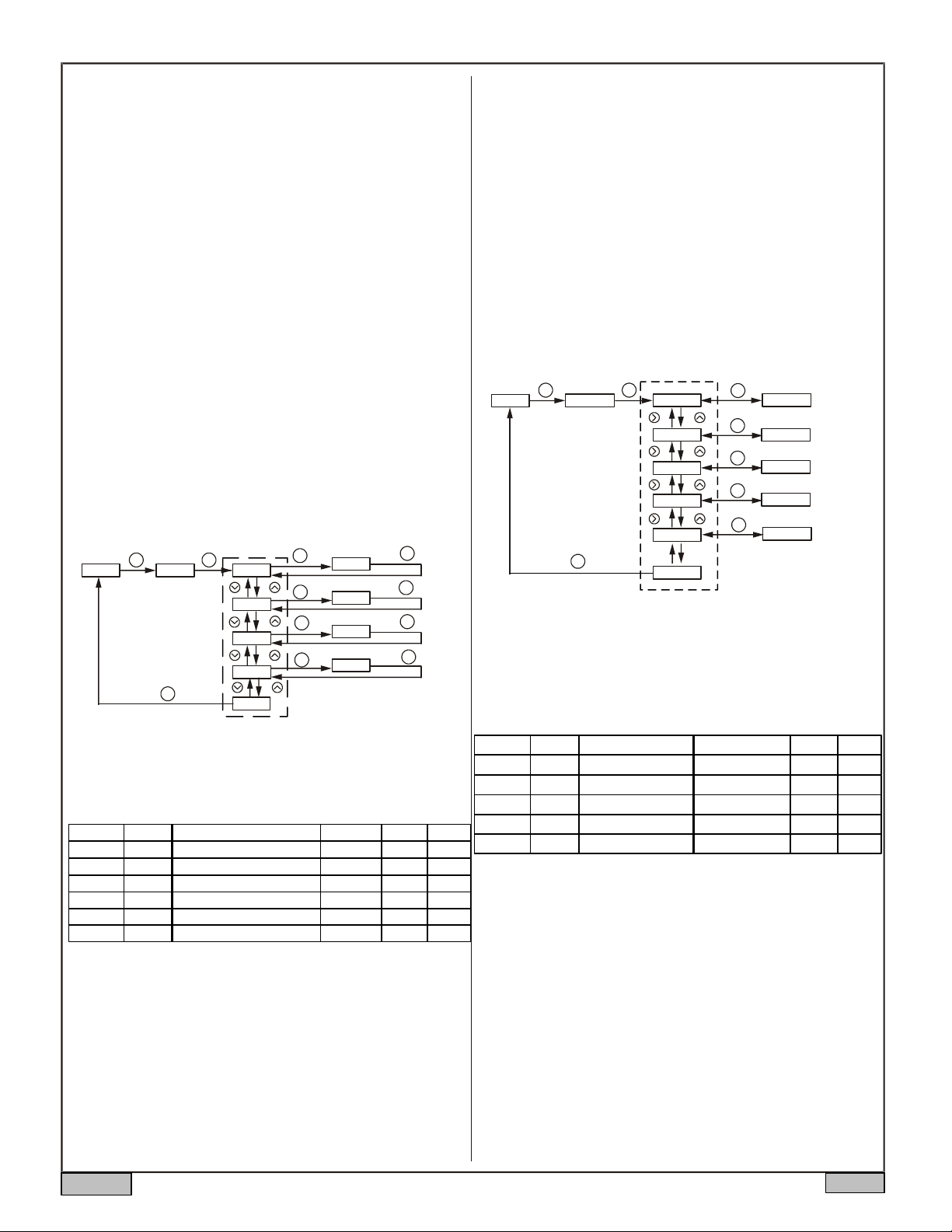
Steps to set an alarm are described below as well as in the flow chart in Figure 4:
(1) Press SET key, change the code to 0001, and press SET again to enter alarm
setting mode.
(2) Press Up and Down key to select a parameter (AH1, AL1, AH2, or AL2).
(3) Press SET to view the value of the parameter.
(4) Use Shift, Up, and Down key to change the value.
(5) Press SET key to confirm the value and exit from this parameter.
(6) Press Up or Down key to select the new parameter.
(7) To exit this mode, press SET key when “End” is displayed.
The procedure is showed in the flow chart in Figure 4.
Operation Mode
XXXX
Enter Code
SET SET
0001
Parameter Display
AH1
AL1
AH2
AL2
SET
SET
SET
SET
SET
Buzzer On Temp
0480
Buzzer Off Temp
0479
Buzzer On Temp
0250
Buzzer Off Temp
0250
SET
SET
SET
SET
END
Figure 4. Steps of setting alarms. In this example, alarm1 is set as a high limit alarm
at 480; alarm2 is disabled.
7. System settings (code 0089)
The parameters for system configuration is listed in Table 1.
Table 1. System configuration parameters.
Symbol
Inty
PSb
FILT
C-F
Brit Brit
END END
Note 1. Inty (Input sensor type). This parameter defines the sensor type that is used
for the thermometer. If you purchased the thermometer bundle, it is already set for
the probe included in the package. You don’t need to change it.
Note 2. PSb (input offset). This is to set an offset value to compensate the error
produced by the sensor. For example, if the meter displays 5 ºC when probe is in ice/
water mixture, setting PSb= -5 will make the meter display 0 ºC.
Note 3. FILt (digital Filter). If the temperature reading fluctuates due to input noise, a
digital filter can be used to smooth the input signal. “FILt” may be configured in the
range of 0-3. Higher the value, stronger the filtering effect. A strong filter increases
the stability of the readout, but causes longer delay in responding to the temperature
change. Set FILt=0 will disable the filter.
Note 4. C-F (temperature unit). Set to C if you want to display temperature in
Celsius. Set to F for Fahrenheit.
Name
Inty
PSb
FILT
C-F
Description
Input sensor type
Input offset
Digital filter
Temperature unit
Brightness level of dimmed LED
Exit
Setting Range
K
-1000 ~ 8000
0 ~ 3
°C, °F
1-4
Initial
k
0
0
°F
1 5
Note 5. Brit (display dimmer). This parameter sets the brightness level of the
dimmed LED display. You can switch the LED brightness level between the dimmed
and the normal using UP key. However, the normal brightness level of the LED
display is equal to level 4. So if Brit is set to 4, you won’t see and change in the
brightness of LED display when pressing UP key.
Note 6. End. Exit the parameter setting mode.
Steps to set system parameters are described below as well as in the flow chart in
Figure 5:
(1) Press SET key, change code to 0089, and press SET again to enter the system
configuration mode.
(2) Press Up or Down key to select the parameter to be changed.
(3) Press SET to view the value of the parameter.
(4) Press Shift, Up, and Down key to enter a new value.
(5) Press SET to confirm.
(6) Press Up or Down to select the new parameter.
(7) To exit the menu, press SET when “End” is displayed.
Operation Mode
XXXX
Enter Code
SET SET
0089
SET
Parameter Display
Inty
PSb
FiLT
C-F
Brit
Input Type
SET
xxxx
Input Offset
SET
xxxx
Digital Filter
SET
xxxx
Temperature Unit
SET
xxxx
Brightness level of dimmed LED
SET
xxxx
End
Figure 5. Flow chart of how to set system configuration parameters.
8. Wireless connection setting (code 0110)
The parameters for wireless connection can be accessed by code 0110. The
parameters are listed in Table 2.
Table 2. Wireless connection parameters.
Symbol
bAud
Tdly
Note
tACy
End End
1
2
Note 7. Baud (Baud rate for communication). This should be left as default.
3
Note 8. Id (Unit ID). Each slave unit should be assigned with a unique Unit ID. The
default value is 1. The value of the Unit ID can range from 0 to 240. A master unit can
4
communicate with up to 10 slave units. For example, if you have two slave units, you
can set their Unit ID to 1 and 2 respectively. Then, when the master Unit ID is set to 1, it
6
will read the temperature of slave unit 1. When the master Unit ID is set to 2, it will read
from slave unit 2. Set two slave units to the same ID number will cause crashes.
Note 9. tdly (Hand shake time). This is the time interval (unit in seconds) after which the
master unit will attempt to read signal from the slave unit again. If the master unit
receives signal during this hand shake time, it will refresh and display the current
reading at the assigned cycle rate. Otherwise, it will display the previous reading for the
rest of the current hand shake cycle. If there is still no signal received during the entire
hand shake time, the master unit will display four dashes (“- - - -“). This setting can
prevent the master unit from frequently switching between temperature reading and
four dashes. If the master unit and the slave unit is far away from each other or the
signal is weak, user should increase the hand shake time. Placing the master and slave
unit too close to each other may also result in no reading on the master unit.
Note 10. tACy (Sampling rate). This parameter sets how frequently the slave unit
refresh its reading . The default sampling rate is 1 per second. The unit is s-1or Hz.
Note *. These two parameters are only available on the master unit.
Name
bAud
Id
Id
tdly *
tACy *
Description
Baud rate
Unit ID
Hand shake time
Sampling rate
Exit
Setting Range
1200, 2400, 3600, 9600
0 ~ 240
2 ~ 60
0.5 ~ 60 per second
Initial
9600
1
3.0
1.0
Note
7
8
9 *
10 *
2013.11
P2/2
Page 3

AUBER INSTRUMENTS WWW.AUBERINS.COM
9. Peak value setting (code 0037)
The peak value (the highest measured temperature) and the peak time (the time at
which the peak values is read) can be stored. These parameters for peak values can
be accessed by code 0037. The parameters are listed in Table 3 below.
Table 3. Alarm setting parameters.
Symbol
mA
mAt
End End Exit
Name
mA
mAt
Description
Peak value
Peak value time
Setting Range
On/off
On/off
Initial
On
On
Note
11
12
Note 11. mA (Peak Value). The highest temperature reading. By default this function is
turned on. The Peak Value will be kept in the memory unless cleared. After the unit is
powered on, the previously recorded Peak Value and its time stamp will remain in the
memory unless: 1) a new peak value overwrites the previous peak value, 2) or the
memory has been reset. Hold the Down key for 2 seconds will reset both the peak
value and its time stamp to 0. The recorded peak value can be checked by pressing
DOWN key during the normal operating mode; press DOWN key again to display the
Peak Value Time; press and hold Down key for 2 seconds to clear the stored Peak
Value and the Peak Value Time.
Note 12. mAt (Peak Value Time). The time stamp of the Peak Value. By default this
function is turned on. The time is tracked by the build-in timer which is activated
whenever the mAt function is being turned on. The current Peak Value Time will be
overwritten by the new Peak value time. The Peak value time can be checked by
pressing DOWN key again in the peak value mode. Pressing the DOWN key 2 seconds
will clear the Peak value as well as the Peak value time. Every time the unit is restarted
or the Peak Value is cleared, the timer will start over again (unit in seconds).
12. Communication Between the Master Unit and Slave Units.
When the communication between a master unit and a slave unit is established, all the
settings and operations on these two units are “mirrored”, except for the Unit ID and
the operation which temporarily mute the alarm (for the safety reason). You can set all
of these parameters from either the slave or the master unit.
1) Mirrored operations and parameters. Operations and readings on one unit will be
mirrored to the other unit. Change of the alarm setting on the master unit will also be
synchronized to the slave unit, or vice versa. The temperature reading and peak
values on the slave unit will also be synchronized between the master unit and the
slave unit. For example, when the peak value is cleared from the slave unit, the new
peak value will be recorded at the slave unit and then mirrored to the master unit.
When the peak value is cleared from the master unit, this operation will also be
synchronized to the slave unit, and the peak value will be cleared.
2) Muting the alarms. When you press the SHIFT key to mute the alarm buzzer, it will
only be effective to the buzzer on this unit. The buzzer on the other unit will continue
sound until temperature left the alarm zone, or the SHIFT key on that unit is pressed.
3) Placing distance. Placing the master and the slave units too far or too close will
result in bad signal reception on the master unit. Signal reception can be affect by
distance, physical obstacles, and other factors. The master unit and the slave unit can
be placed at least 100 feet away in an open space.
11. Placing and Mounting the Meter.
The meter should be placed in a working environment where temperature is -20-50°C
(0-100°F). It should be placed away from high heat to protect the plastic housing and
electronics. Two mounting options are provided:
1) A pair of Velcro fastener. The Velcro has a pressure sensitive adhesive backing.
You can remove the protective film from the hook piece and stick it to the back of the
meter (see Figure 6). Then remove the protective film from the loop piece and install it
onto the wall. Please note that the pressure sensitive adhesive on Velcro is industrial
grade with strong holding force. It needs to be stick on a solid surface. Don’t put it on a
drywall because it may peel off the paint if you decided to remove it later.
2) A stainless steel mounting plate. The plate allows the meter to be hung on a hook
or a nail. It also allows the meter to be permanently mounted with a screw. The
bottom part of the stainless steel mounting plate is covered with pressure sensitive
adhesive. To install it onto the meter, peel off the pink colored releasing film; press it
firmly onto the back of the meter (see figure 6).
NOTE: This equipment has been tested and found to comply with the limits for a
Class B digital device, pursuant to part 15 of the FCC Rules. These limits are
designed to provide reasonable protection against harmful interference in a residential
installation. This equipment generates, uses and can radiate radio frequency energy
and, if not installed and used in accordance with the instructions, may cause harmful
interference to radio communications. However, there is no guarantee that
interference will not occur in a particular installation. If this equipment does cause
harmful interference to radio or television reception, which can be determined by
turning the equipment off and on, the user is encouraged to try to correct the
interference by one or more of the following measures:
Reorient or relocate the receiving antenna.
Increase the separation between the equipment and receiver.
Connect the equipment into an outlet on a circuit different from that to which the
receiver is connected.
Consult the dealer or an experienced radio/TV technician for help.
Caution: Any changes or modifications to this device not explicitly approved by
manufacturer could void your authority to operate this equipment.
This device complies with part 15 of the FCC Rules. Operation is subject to the
following two conditions: (1) This device may not cause harmful interference, and (2)
this device must accept any interference received, including interference that may
cause undesired operation.
Figure 6. Velcro mounting (left) and stainless steel plate mounting (right).
2013.11
Auber Instruments
5755 North Point Parkway, Suite 99
Alpharetta, GA 30022
www.auberins.com
Email: info@auberins.com Tel: 770-569-8420
P2/2
 Loading...