

Auber WSD-1501GPH Operation & Instruction Manual

Copyright 2007-2016, Auber Instruments Inc. All Rights Reserved.
No part of this manual shall be copied, reproduced, or transmitted in any way without the prior, written consent of Auber Instruments.
Auber Instruments retains the exclusive rights to all information included in this document.
Operation Instruction Manual
WSD-1501GPH
Programmable PID Temperature Controller with Dual Probe
*
Version 1.0 (September, 2016)
Auber Instruments
5755 North Point Parkway, Suite 99
Alpharetta, GA 30022
770-569-8420
www.auberins.com
Introduction
Thank you for purchasing the Auber WS series temperature controller. We sincerely
appreciate your decision and trust that our machine will meet your expectations in both
the quality of the result and the value of our product. While we are delighted that you may
be anxious to operate the controller for your project, a few minutes of your time reading
through this manual will only serve to enhance your experience in the months and years
ahead. In particular, we urge you to read through the safety warnings below. Although
this plug-and-play controller is very easy to operate, the process involves high
temperature and high wattage appliances and your safety is paramount.
SAFETY WARNINGS
This controller is designed only to be used with devices that have limited power
and their own thermal cut off protection, such as a thermostat or thermal fuse in
case of controller failure.
Do not place any objects on the top of controller surface which is used to vent
excess heat during its operation.
The maximum electric current this controller can handle is 15 ampere. For 120
volt AC in US and Canada, this limits the heater power to 1800 watts.
Always place the sensor in the controlled subject when the controller is on. Before
turning on the controller, please make sure the sensor is placed inside the
container to be controlled. Leaving the sensor outside of the solution will form an
open loop operation. If the sensor is left outside, controller will assume the
temperature is low even if the controlled subject is already very hot. The controller
will provide full power to the heater. It will not only overheat the controller, but also
*
Patent pending

2
damage your appliance, and even cause a fire.
This controller is designed to control the devices recommended by Auber
Instruments only. Using it to control a not recommended device can be dangerous
and cause fire. Auber Instruments is not liable for damages caused by misuse of
the controller. If you are not sure the controller can be used, please contact Auber
Instruments before use.
If an abnormal display or noise is observed, turn the controller off, unplug the
power cord and contact the manufacturer before using it again.
Clean the controller only when it is cool and unplugged.
Do not allow children to operate the controller.
Specifications
Number of storable recipes 8
Number of steps in each recipe 6
Input voltage US 120V, European 220V, 50/60 Hz
Output voltage The same as the input.
Maximum Current 15A for 120V AC, 12A for 220V AC, 5A for the smoke
generator output.
Controller Mode PID, PI, PD or P.
Output switching device Built-in optically isolated solid state relay with zero voltage
crossing switching.
Sensor type PT1000 RTD sensor
Control probe dimension 4 mm diameter x 40 mm long.
Food internal temperature probe dimension
4 mm diameter x 150 mm.
Probe cable length 5 ft (1.5 meter) (both probes)
Timer range 6 steps with 0.1 to 99.9 hours for each step.
Temperature resolution 1 °C or 1 °F.
Temperature display unit Celsius or Fahrenheit.
Temperature display range -40-400 °C, or -40-750°F.
Mini. Control Temperature 5 °C (9 °F) above ambient with smoker generator off, 22
°C (40 °F) above ambient with smoker generator on.
Max. Control Temperature 350 °C (660 °F).
Temperature accuracy +/-1°C
Smoker generator control output maximum current
3A at 120V
Dimension 6 x 3 x 8.3 inch (155 x 80 x 210 mm) WxHxD.
Weight 3.2lb (1.4 kg).
Warranty One (1) year for the controller, 90 days for sensors.
3
Note: This controller has US input plug and output socket that meet the NEMA 5-15
standard. For international order, user can get a converter from local electronics store to
convert the connection. For countries that use 220-240VAC power line, the maximum
control power of this controller is 2800 Watts.
Operating Instructions
1. Description of the controller
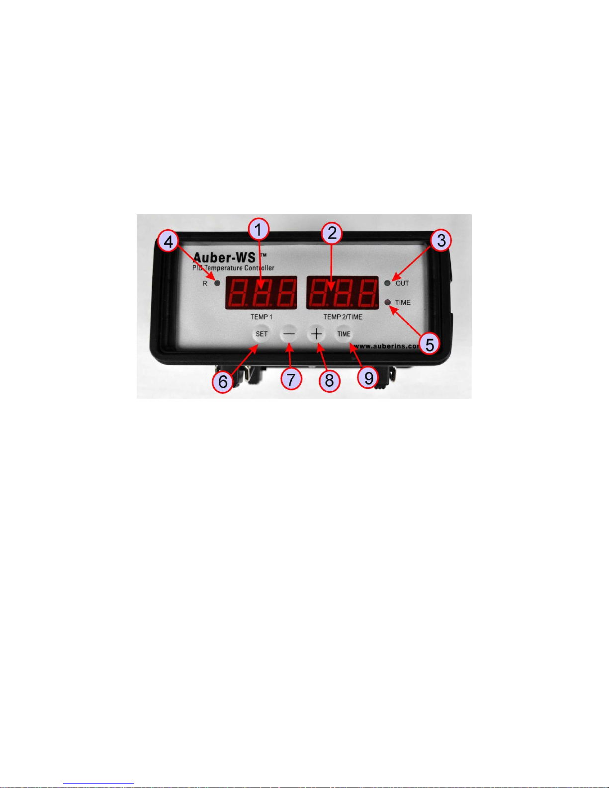
Figure 1. Front Panel.
1) TEMP1, Left window - During normal operation, it displays the temperature values
of probe 1. When high or low limit alarm of probe 1 is on, this window will flashing
between the alarm type (AH1or AL1) and the temperature. In the parameter setting
mode, it displays the controller's system parameters.
2) TEMP2/TIME, Right window - During normal operation, it displays the
temperature value of probe 2 (food internal temperature probe), or the time passed
since the controller was powered up. When high limit alarm of probe 2 is on, this
window will flashing between AH2 and the temperature. In the parameter setting
mode, it displays the value of the parameter.
3) Output status indicator - This LED indicates the output status that should be
synchronized with heater. When it is on (lit), the heater is powered. When it is off,
the heater power is off. When it is flashing, it means the heater is on and off
intermittently to reduce the power output. It should be synchronized with the power
light on the cooking device.
4) Smoker generator control output status indicator - When it lit, the smoker
generator control output is on. When it is off, the output is off.
4
5) Timer status indicator - When lit, right window shows the time passed since
power up. When it is off, right window shows the current temperature detected by
the probe 2.
6) SET Key - For showing current temperature settings, getting into parameters
setting mode and confirming various actions taken.
7) “-” Key - To decrement displayed value when in controller is in the parameter
setting mode. During normal operation, press it to cancel the alarm.
8) “+” Key - To increment displayed value when in controller is in the parameter
setting mode. During normal operation, press it will change the left window from
temperature to display which step the program is at.
9) Time Key - Change the display in right window between current timer and
temperature values.
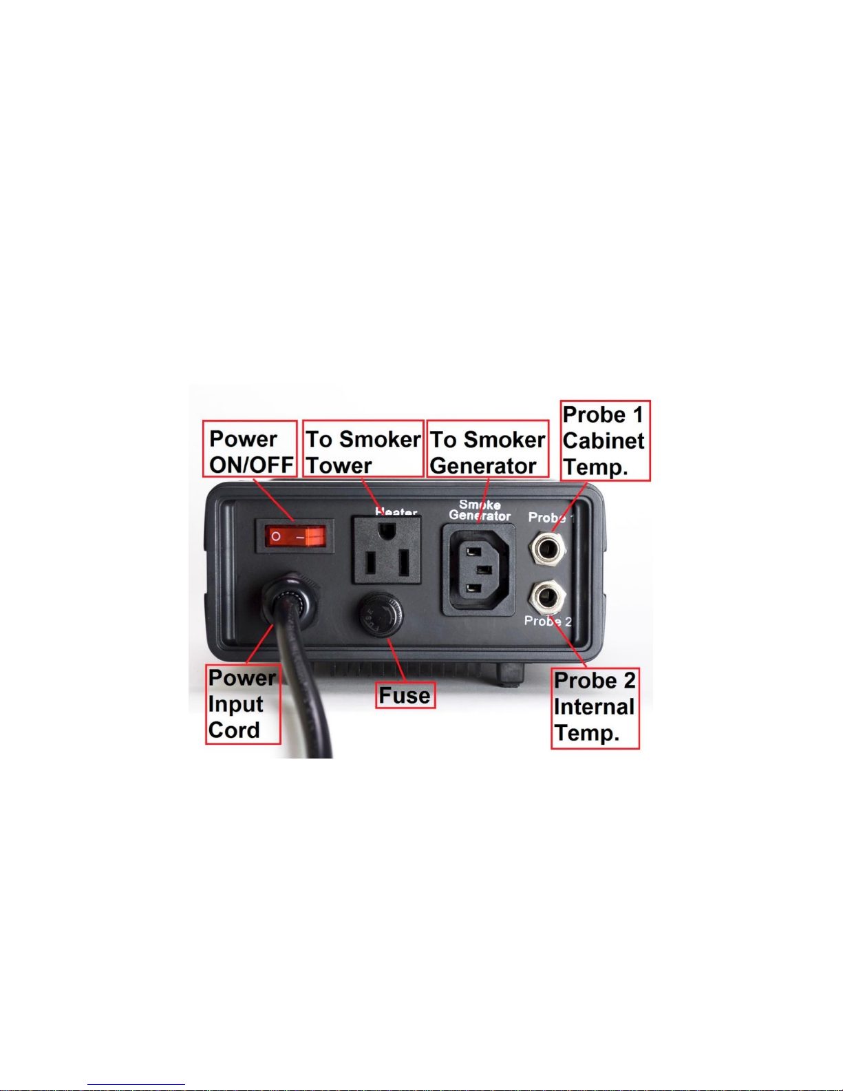
Figure 2. Back Panel.
5
2. Connecting and operating the controller
Install the sensor.
(Note: If you ordered wall mount sensor instead of free hanging sensor, please see the
separate instruction in the CD for its installation)
The controller is supplied with two probes. The one with the short tip is for measuring the
cabinet temperature. We name it probe 1. It needs to be plugged to the top sensor jack
at the back of the controller. The long probe with a bend at the end is for the meat
internal temperature measurement. It needs to be plugged to the bottom sensor jack at
the back of the controller. The tips of the probes are dropped into the damper hole. Place
a piece of tape on the top of the smoker tower to hold them in place. The tip of probe 1
should be placed close to the food but high enough so that it does not touch the food.
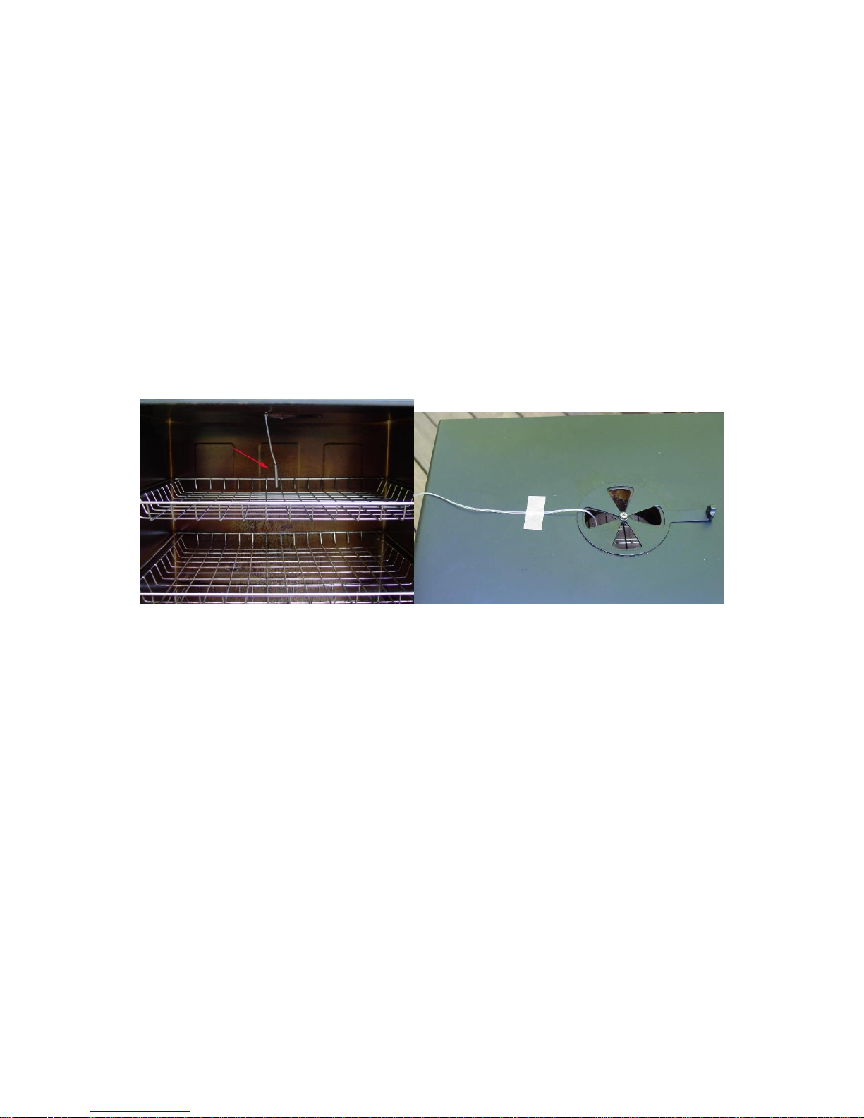
(See Figure 3). The tip of probe 2 is to be inserted into the meat.
Figure 3. Sensor position. Left, the sensor should be placed close to the food but high
enough so that it does not touch the food. Right, hold the sensor in place by a piece of
tape.
For the “Original” and Stainless Steel Bradley smoker, the Temperature Heat Control
Switch on the smoker tower should be slid to the Hi position (Most right).
There are several ways to power up the controller and Bradley Smoker.
6
Smoke
Generator
Smoker
Tower
Cable B
Cable A
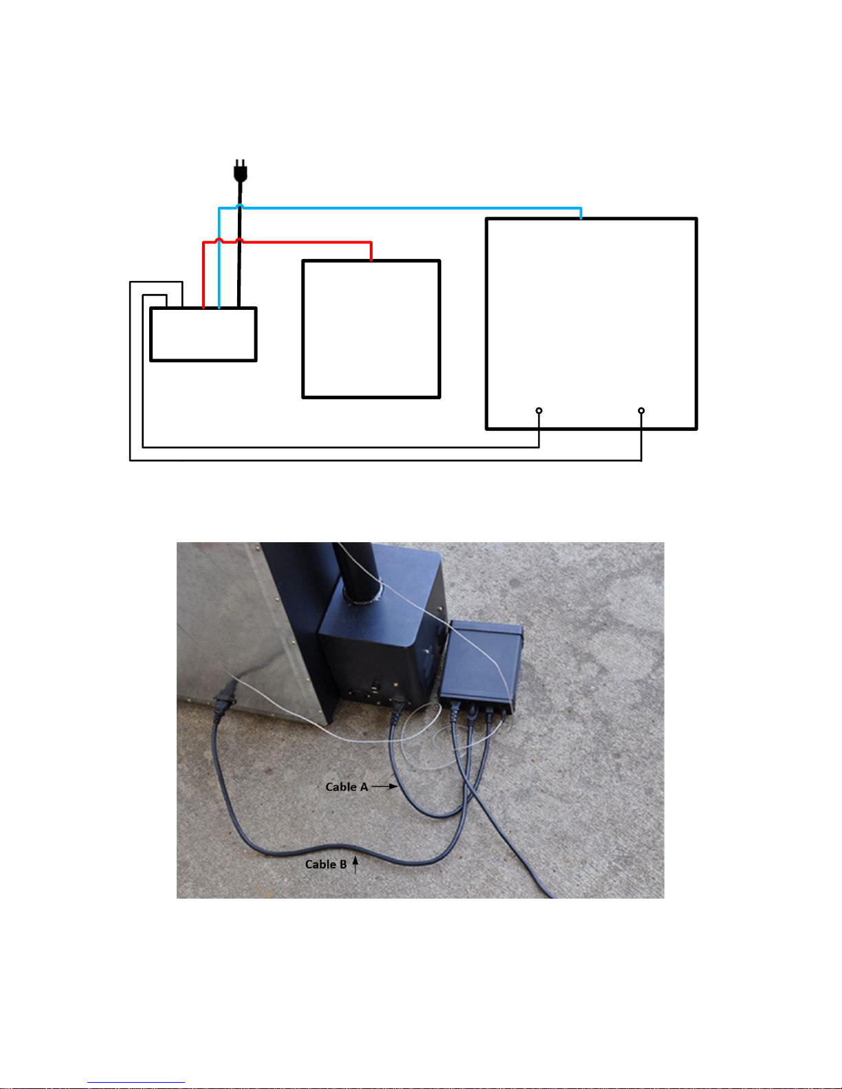
Figure 3.1 Power Cable wiring for Original Bradley Smoker
Cable A: Power cable for Smoker Tower, C14 plug
Cable B: Power cable for smoke generator, NEMA5-15P plug
1) Connection for Bradley Original Smoker, with control of the smoker generator.
a) Connecting the controller to the power outlet, you should use the power cord that
came with the Bradley Smoker for connecting the smoker generator to the power outlet.
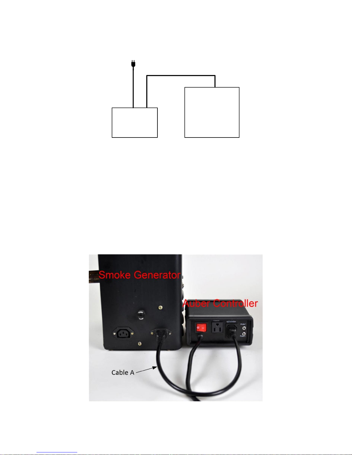
b) Connecting the controller to the smoker generator. You should use the power cord that
originally was used for connection between the smoker generator and smoker tower.
Figure 4. Connection between the controller and Bradley Original Smoke generator.
7
c) Connecting the controller output to the Bradley Smoker Tower with the power cord that
came with the Auber Controller
Auber
Controller
Smoke
Generator
Smoker Tower
Probe 1:
Cabinet Temp
Probe 2:
Internal Temp
Cable A
Cable B
To Power Outlet
Figure 5. Diagram
Figure 6. Back view
8
Figure 7. Connection between the controller and smoker
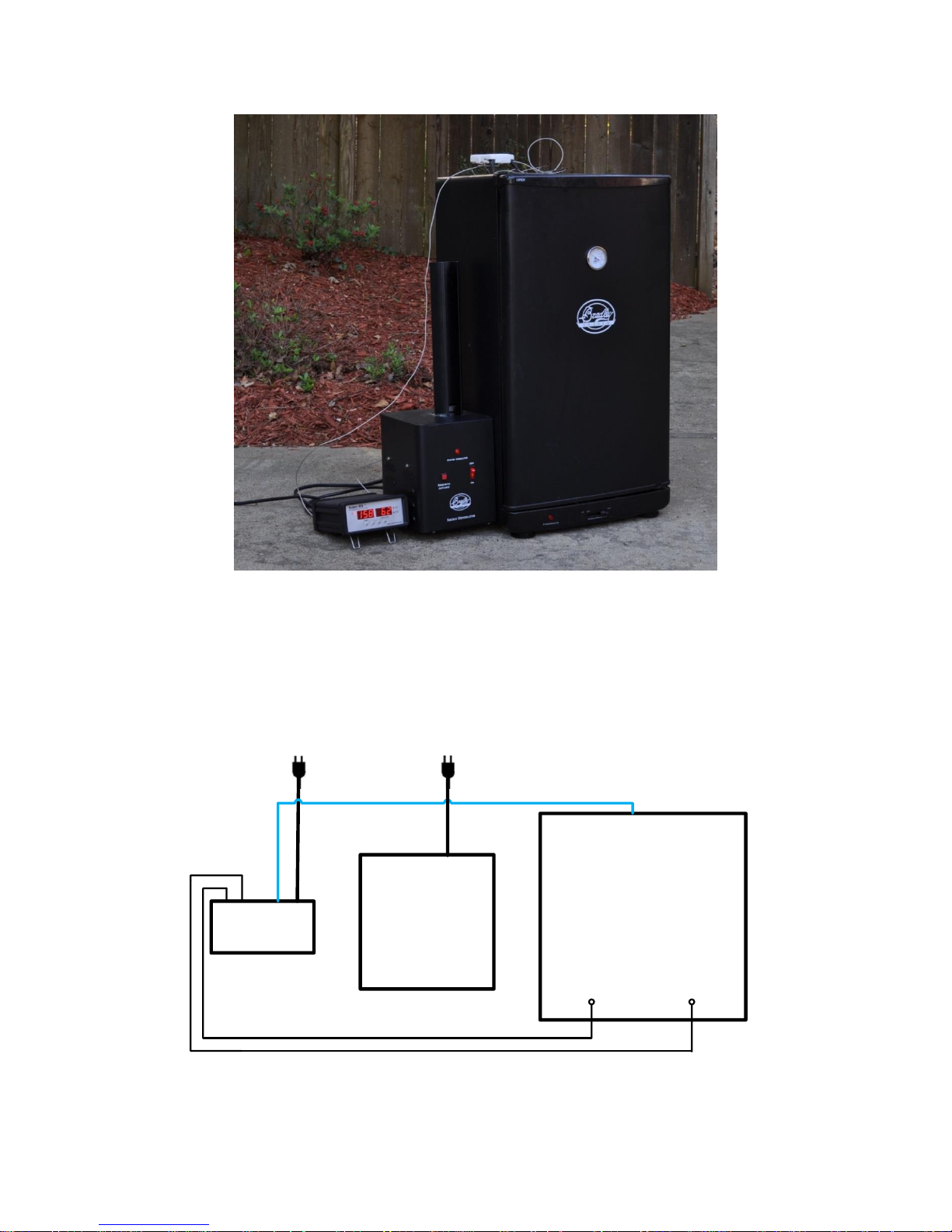
2) Connection for Bradley Digital Smoker.
For the Bradley Digital Smoker, both controller and smoker generator should be
connected directly to the wall outlet. Connect the controller output with the smoker tower.
Auber
Controller
Smoke
Generator
Smoker Tower
Probe 1:
Cabinet Temp
Probe 2:
Internal Temp
Cable C
Cable B
To Power Outlet
To Power Outlet
Figure 8. Connection for Bradley Digital Smoker
Cable C is extra 18 AWG power cord, same as Cable B

9
3. Programming the smoking temperature profile
A total of 6 steps can be programmed for this controller. Each step contains the set
temperature (C-X) and an ending criteria setting (E-X), where “X” is the step number (e.g.
Step 4 temperature is represented by C-4 and step 4 ending criterion is represented by
E-4). The ending criterion determines how does controller finish the current step and
start the next step. There are two options for the user, t and F. Set E-X to t if you want
step X to be end by a preset time. Set E-X to “F” if you want step X to end by a preset
temperature of the internal probe.
After you set E-X to “t”, you will be asked to set t-X for the time. Time is defined as the
duration between the last step and the next step. Please make sure the time is long
enough for the heater to heat up the smoker. If the time is set too short, the temperature
may not be able to reach the current step temperature setting, before it jumps to the next
step. The time unit is in hours with 0.1 hour resolution. Each 0.1 hour equals to 6
minutes.
If you set E-X to F, you will be asked to set F-X for the temperature of the internal probe.
When all of the E-X are set to t, the controller can operate with only the probe 1 plugged
in.
To program the temperature profile, press SET key once. The display will show C-1 at
the left window and temperature setting on the right window for step 1. Use “+” and “-”
keys to change the setting. When finished, press the SET again to confirm the change.
The display will show E-1 on the left window and the ending criterion setting on the right
window. Use “+” and “-” keys to change the setting. When finished, press the SET again
to confirm the change. The left window will display t-1 or F-1 depending whether t or F is
selected for the E-1. The right window will display the setting for t-1 or F-1. Use “+” and “-”
keys to change the setting. When finished, press the SET again to confirm the change.
The display will go the step 2 setting. It will repeat in the same way as the step 1. After
you program enough step for the recipe, you can program rest of the steps of E-X to t
and set t-X zero.
The temperature setting will not be changed if SET is not pressed (confirmed). After
programming the necessary steps for cooking, you can finish programming by pressing
the SET continuously until it passed T-6 and display the current temperature. You can
also leave the controller alone. The display will return to the normal display mode if no
key is pressed within 15 seconds.
The initial program setting for the controller is listed in
Table 1. This program will control the temperature of the cabinet at 120 °F for 2 hours.
 Loading...