

Auber WS-1500EBPM Operation Instruction Manual

Operation Instruction Manual
WS-1500EBPM
Precision PID Temperature Controller
Version 1.1
Auber Instruments
5755 North Point Parkway, Suite 99
Alpharetta, GA 30022
770-569-8420
www.auberins.com
May, 2013
Introduction
Thank you for purchasing the Auber WS series temperature controller. We sincerely
appreciate your decision and trust that our machine will meet your expectations in both
the quality of the result and the value of our product. While we are delighted that you may
be anxious to operate the controller for your project, a few minutes of your time reading
through this manual will only serve to enhance your experience in the months and years
ahead. In particular, we urge you to read through the safety warnings below. Although
this plug-and-play controller is very easy to operate, the process involves high
temperature and high wattage appliances, and your safety is paramount.
SAFETY WARNINGS
This controller is designed only to be used with devices that have limited power
and their own thermal cutoff protection, such as a thermostat or thermal fuse in
case of controller failure.
Do not place any objects on the top of controller surface which is used to vent
excess heat during its operation.
The maximum electric current this controller can handle is 15 Ampere. For 120
volt AC in US and Canada, this limits the heater power to 1800 watts. Due to its
compact size and the splash proof design for kitchen applications, the controller
has a limited ability to dissipate the heat generated by the internal solid state relay
during the initial heat up. The initial full power heat up process cannot be more
than 90 minutes. If you system need take longer time to warm up, please read
Appendix 1 “Managing the heat generated by the controller”
Always place the sensor in the controlled subject when the controller is on.
Before turning on the controller, please make sure the sensor is placed inside the
container to be controlled. Leaving the sensor outside will form an open loop
1

operation. If the sensor is left outside, the controller will assume the temperature
is low even if the controlled subject is already very hot. The controller will provide
full power to the heater. It will not only overheat the controller, but also damage
your appliance possibly causing a fire. If the sensor is not permanently mounted
on the system and is left outside of the system, this could become a potential
problem, you should enable the open loop alarm function (see page 11 for
details).
This controller is designed to control the devices recommended by Auber
Instruments only. Using it to control a not recommended device can be dangerous
and cause fire. Auber Instruments is not liable for damages caused by misuse of
the controller. If you are not sure the controller can be used, please contact Auber
Instruments before use.
If an abnormal display or noise is observed, turn the controller off, unplug the
power cord and contact the manufacturer before using it again.
Clean the controller only when it is cool and unplugged.
Do not allow children to operate the controller.
Specifications
Input voltage: 100 to 240 VAC 50 /60 Hz
Output voltage: Same as the input.
Maximum Current: 15A at 120V, 10A at 240V
Fuse Size: 15A Fast blow.
Control Action: Heating (reversed action) or cooling (direct action)
Control Mode PID, PI, PD, P or On/off
Output switching device: Built-in optically isolated solid state relay with zero voltage
crossing switching.
Sensor type: Pt100 RTD sensor
Sensor tip dimensions: 4 mm diameter x 50 mm long.
Sensor cable length, 3 ft (915 mm)
Alarm: High limit alarm and Open loop alarm with LED and
buzzer.
Timer Range: 1 to 9999 minutes for each step. 6 steps total.
Temperature resolution: 0.1 °C or 0.1 °F
Temperature display range: -50.0 to 200.0 °C or -58.0 to 392.0 ° F
Temperature accuracy: 0.1°C or 0.2 °F for 0-85 °C (32.0 to 185.0 ° F)
Dimension: 6x3x7 inch (155 x80x180 mm) W x H x D.
Weight: 2.8 lb (1.3 kg)
Warranty: 1 year for controller and sensor
Operating Instructions
2
1) Description of the controller.
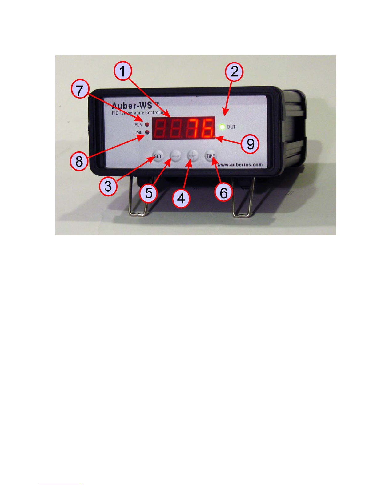
Figure 1. Front Panel
(1) Parameter Window (LED) - For displaying temperature values and controller's
system parameters.
(2) Output status indicator - In normal mode, this LED indicates the heater status.
When it is on (lit), the heater is powered. When it is off, the heater power is off. When
it is flashing, it means the heater is on and off intermittently to reduce the power
output. It should be synchronized with the power light on the cooking device.
(3) SET Key - For showing current temperature settings, entering parameters setting
mode and confirming various actions taken.
(4) “+” Key - To increment displayed value.
(5) “-”Key - To decrement displayed value.
(6) Time Key - Change the Parameter Window between current timer and
temperature values, when pressed.
(7) Alarm indicator - Lit when the alarm is on.
(8) Timer status indicator - In normal mode, when “(8)” is on and “(9)” is flashing,
LED shows the time passed since it’s powered on.
(9) Mode indicator - the small “dot” is used to indicate what mode the controller is in.
When it is flashing and “(8)” stays on, “(1)” is the time that has elapsed since
it’s powered on.
3

When it is flashing “(8)” is off, the controller is in the parameter setting mode.
“(1)” is the value can be changed by using (4) and (5) key.
Figure 2. Back Panel
2) Connecting the controller
Figure 3. Typical connection between the controller and
the heating device (in this example, the cooker).
The connection of the controller should be done in the following steps.
Plug the temperature sensor to the back of the controller.
Plug the power cord to the power outlet on the wall.
4
Turn on the controller to make sure the controller powers up properly, and the
temperature display is in the range expected. Then, turn off the controller.
Plug the heater to the back of the controller. If the heater has a switch, put it in the
off position. Put the sensor inside the container to be controlled.
Turn on the controller.
Turn on the heating device.
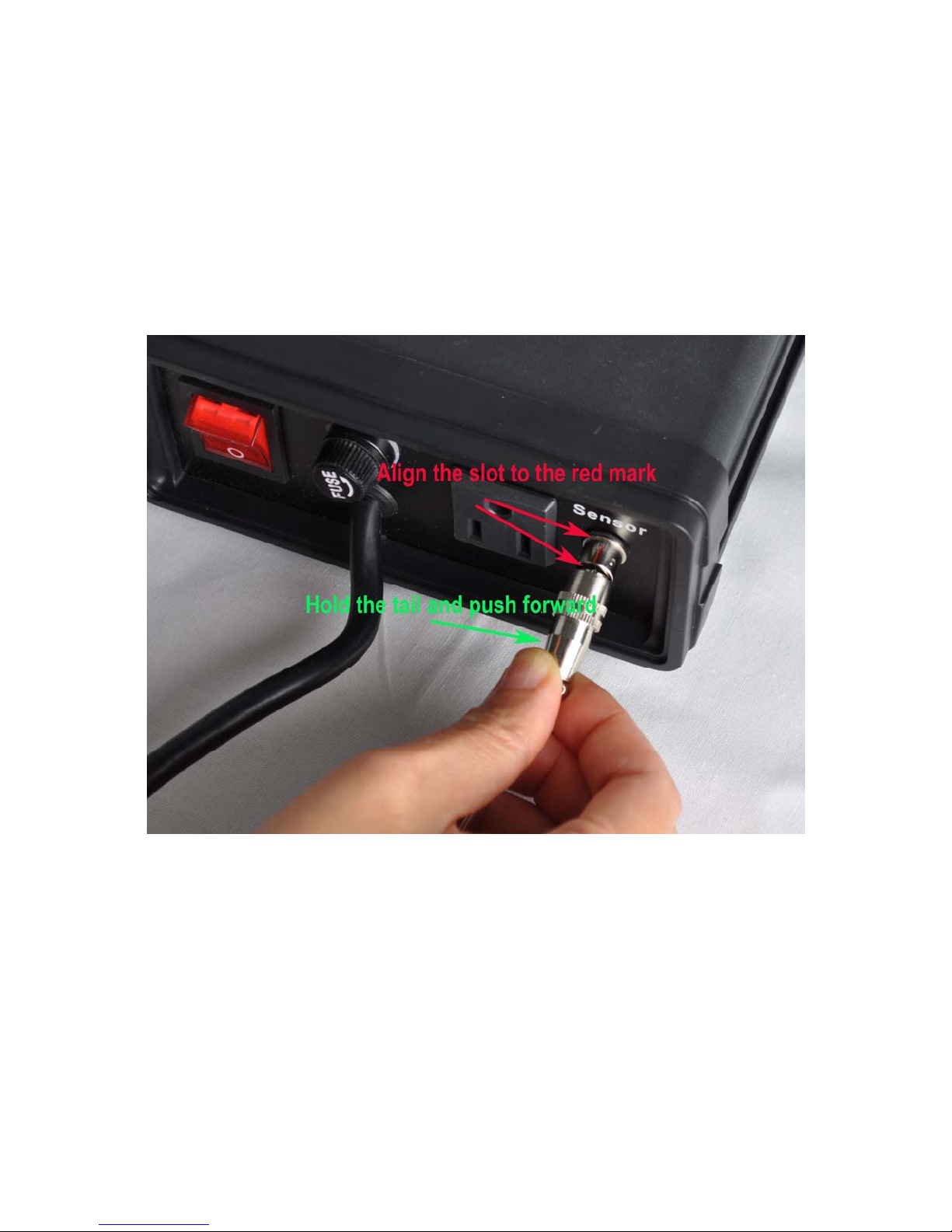
Remark The connector of sensor contains a slot for correct pin connection. It also has a
spring lock to prevent disconnections from accidental pulling on the cable. The following
pictures show how to install and remove it.
5
Figure 4. How to install the sensor.
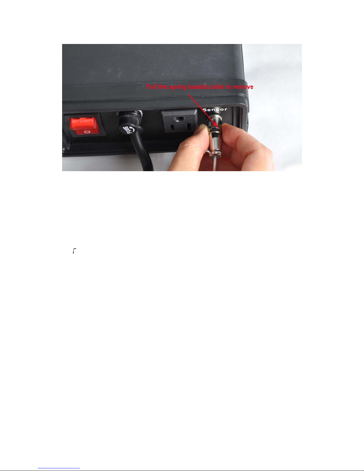
Figure 5. How to remove the sensor.
3) Programming the temperature profile.
A total of 6 steps can be programmed with this controller. Each step contains the
temperature (C0X) and time duration (T0X) setting. They are represented by the symbol
C0X and T0X, where “X” is the step number (e.g. Step 4 temperature is represented by
C04 and step 4 time is represented by T04). The character, “T”, is displayed as the
symbol, “ ”. Time is defined as the duration between the last step and the next step.
Please make sure the time is long enough for the heater to heat up the oven. If the time
is set too short, the temperature may not be able to reach the current step temperature
setting, before it jumps to the next step. The time unit is in minutes with 1 minute
resolution. If the recipe only needs one step, you can program the time of the rest of the
steps to zero.
To program the temperature profile, press SET key once. The display will show C01 for
one second and then display the temperature setting for step 1. Use “+” and “-” keys to
change the temperature setting. When finished, press the SET again to confirm the
change. The display will show T01 for a second and then change to the cook time setting
for step 1. Use “+” and “-” keys to change the cook time setting. When finished, press the
SET again to confirm the change. The display will go the step 2 setting. The following is
the flow chart for the setting procedure.
6
 Loading...