

Auber WS-1200CPH Operation & Instruction Manual

1
Operation Instruction Manual
*
*
WS-1200CPH
Programmable Precision PID Temperature Controller
Version 1.5
Auber Instruments
5755 North Point Parkway, Suite 99
Alpharetta, GA 30022
770-569-8420
www.auberins.com
May, 2013
Introduction
Thank you for purchasing the Auber WS series temperature controller. We sincerely
appreciate your decision and trust that our machine will meet your expectations in both
the quality of the result and the value of our product. While we are delighted that you may
be anxious to operate the controller for your project, a few minutes of your time reading
through this manual will only serve to enhance your experience in the months and years
ahead. In particular, we would urge you to read through the safety warnings below.
Although this plug-and-play controller is very easy to operate, the process involves high
temperature and high wattage appliances and your safety is paramount.
This controller is designed only to be used with devices that have limited power
and their own thermal cut off protection, such as a thermostat or thermal fuse in
case of controller failure.
Do not place any objects on the top of controller surface which is used to vent
excess heat during its operation.
When opening the cover of a rice cooker or slow cooker that has been running for
extended period of time, the cover will carry a lot of condensation that can drip
everywhere. Avoid dripping the water over the controller.
The maximum electric current this controller can handle is 12 amperes. For 120
volt AC in US and Canada, this limits the heater power to1440 watts. In addition, if
the heater power is more than 1400 watts, the volume of the pot is also limited to
less than 10 gallons (or 38 liters). Due to its compact size and the splash proof
Patent pending
SAFETY WARNINGS

2
design for kitchen applications, the controller has a limited ability to dissipate the
heat generated by the internal solid state relay during the initial heat up process.
The initial full power heat up process cannot be more than 90 minutes. If you have
a pot that is larger than 5 gallons (19 litters), please read Appendix 1 “Managing
the heat generated by the controller”
Always place the sensor in the controlled subject when the controller is on. Before
turning on the controller, please make sure the sensor is placed inside the
container to be controlled. Leaving the sensor outside of the solution will form an
open loop operation. If the sensor is left outside, controller will assume the
temperature is low even if the controlled subject is already very hot. The controller
will provide full power to the heater which will not only overheat the controller but
also damage your appliance, possibly causing a fire.
The 16 AWG power cord provided with your controller is specially designed for
high power applications. Do not replace it with a regular computer power cord
when the heating/cooking device is more than 1200 watts.
This controller is designed to control the devices recommended by Auber
Instruments only. Using it to control a not recommended device can be dangerous
and cause fires. Auber Instruments is not liable for damages caused by misuse of
the controller. If you are not sure the controller can be used, please contact Auber
Instruments before use.
If an abnormal display or noise is observed, turn the controller off, unplug the
power cord and contact the manufacturer before using it again.
Clean the controller only when it is cool and unplugged.
Do not allow children to operate the controller.
Specifications
Input voltage: 100 to 240 VAC 50 /60 Hz
Output voltage: Same as the input.
Maximum Current: 12A at 120V, 10A at 240V
Fuse Size: 15A Fast blow.
Controller Mode: PID, PI, PD or P.
Output switching device: Built-in optically isolated solid state relay with zero voltage
crossing switching.
Sensor tip dimensions: 4 mm diameter x 40 mm long.
Sensor cable length: 5 ft (1.5 m)
Timer Range: 0.1 to 99.9 hours for each step, 6 steps total
Temperature resolution: 1 °C or 1 °F
Temperature display range: -10 to 200 °C or 14 to 392 ° F
Temperature control range: +5 °C (°F) from room temperature to 195 °C (383 °F)
Temperature accuracy: ±1°C (±2°F)
Dimension: 6.5 x 3 x 5.2 inch (170 x 80 x 135 mm) W x H x D.
3
Weight: 2.2 lb (1 kg) without power cord.
Note, for international orders (except Canada), the input power cord is not included due
to its weight and different plug requirement. The controller has standard IEC 320 C13/14
socket. Users can use a power cord that meets the local standard to power it. Please
make sure the wire gauge can carry the maximum current required. In addition, an
adaptor that can convert the output socket (NEMA 5-15) to the socket of local standard is
needed.
Operating Instructions
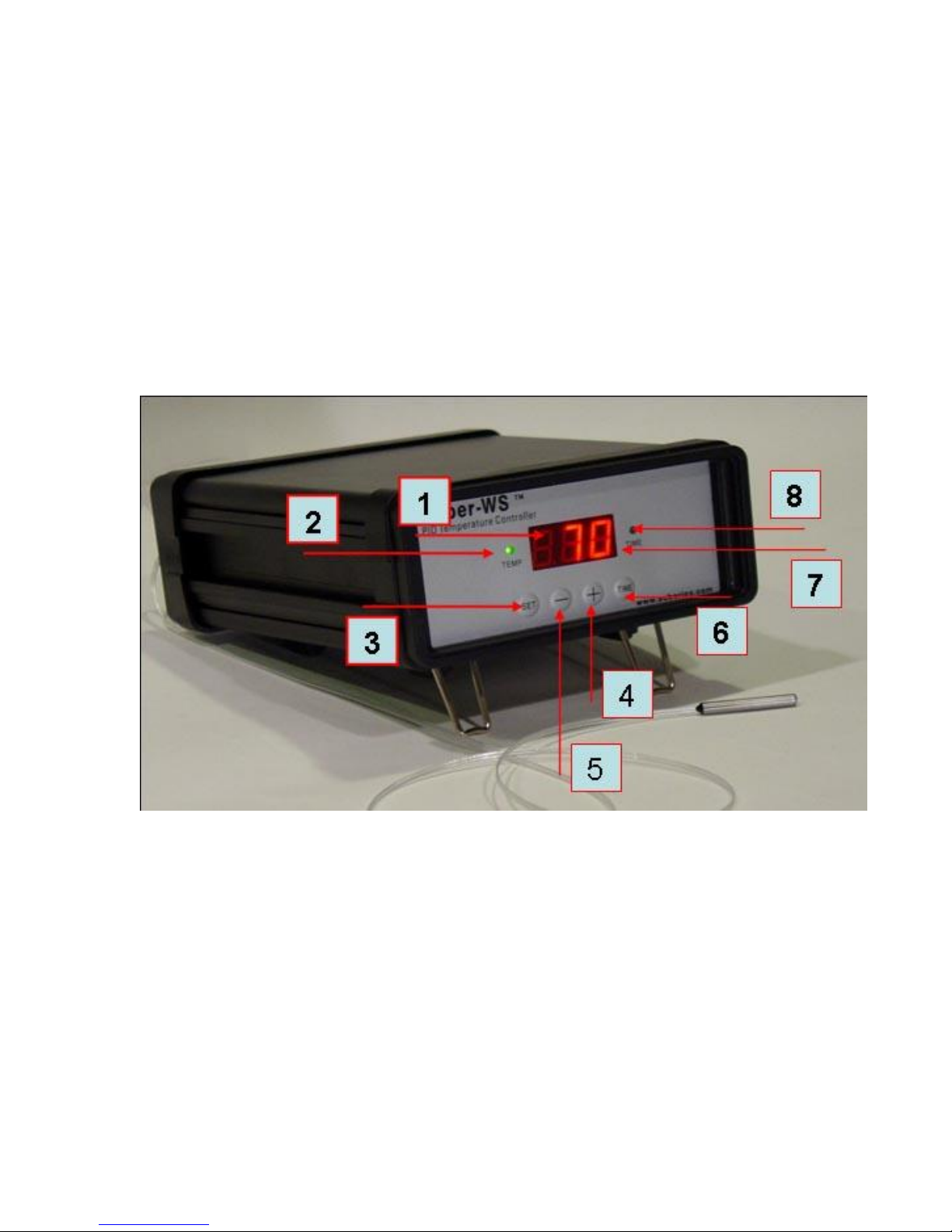
1) Description of the controller.
1) Parameter Window (LED) - for displaying temperature values and controller's
system parameters.
2) Output status indicator - In normal mode, this LED indicates the heater status.
When it is on (lit), the heater is powered. When it is off, the heater power is off.
When it is flashing, it means the heater is on and off intermittently to reduce the
power output. It should be synchronized with the power light on the cooking
device.
3) SET Key - for showing current temperature settings, entering into parameters
setting mode and confirming various actions taken.
Fig 1. Front Panel
4
4) “+” Key - To increment displayed value.
5) “-“ Key - To decrement displayed value.
6) Time Key – Change the Parameter Window between current timer and
temperature values, when pressed. It also displays which step the program is at
before the timer is displayed.
7) Mode indicator, the small “dot” – if it is flashing and the Timer Status Indicator
(“8)”) is lit, the value displayed in the Parameter Window is time passed since
power up. If it is flashing but Timer Status Indicator (“8)”) is off, the value displayed
in the Parameter Window is the parameter that needs to be set. The controller is
either in the programming setting mode or parameter setting mode.
8) Timer status indicator- In normal mode, When “8)” is on and “7)” is flashing, LED
shows the time passed since the controller powered on. When it is off, the LED
shows the current temperature detected by the sensor probe
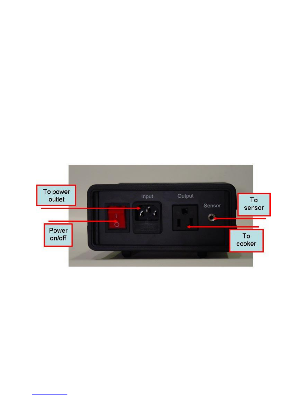
2) Connecting and operating the controller
Fig 2, Back Panel
5
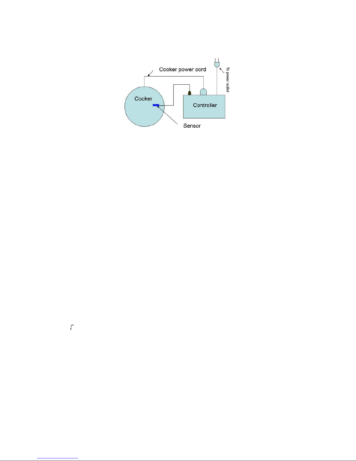
Fig 3. Typical connection between the controller and the heating device (in this example,
the cooker).
The connection of controller should be done in the following steps.
Plug the temperature sensor to the back of the controller.
Plug the power cord to the back of the controller and the other end to the power
outlet on the wall.
Turn on the controller to make sure the controller powers up properly. The
temperature display is in the range expected. Then, turn off the controller.
Plug the heater to the back of the controller. If the heater has a switch, put it in the
off position. Put the sensor inside the container to be controlled.
Turn on the controller.
Turn on the heating device.
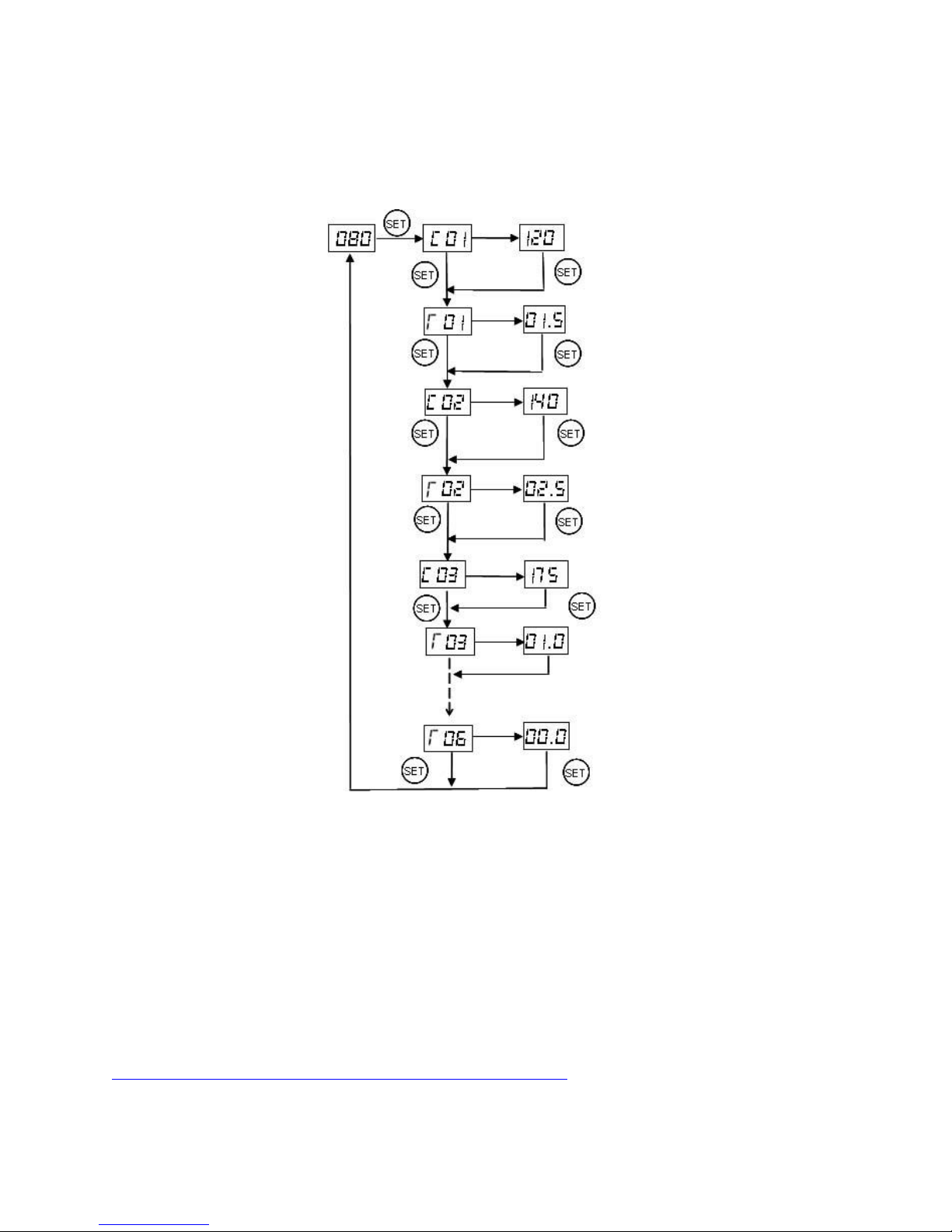
3) Programming the smoking temperature profile.
A total of 6 steps can be programmed for this controller. Each step contains the
temperature (C0X) and time duration (T0X) setting. They are represented by the symbol
C0X and T0X, where “X” is the step number (e. g. Step 4 temperature is represented by
C04 and step 4 time is represented by T04). The character, “T”, is displayed as the
symbol, “ ”. Time is defined as the duration between the last step and the next step.
Please make sure the time is long enough for the heater to heat up the smoker. If the
time is set too short, the temperature may not be able to reach the current step
temperature setting, before it jumps to the next step. The time unit is in hours with 0.1
hour resolution. Each 0.1 hour equals to 6 minutes. If the recipe only needs one step,
you can program the time of the rest of the steps to zero.
To program the temperature profile, press SET key once. The display will show C01 for
one second and then display the temperature setting for step 1. Use “+” and “-“ keys to
change the setting. When finished, press the SET again to confirm the change. The
6
display will show T01 for a second and then change to the cook time setting for step 1.
Use “+” and “-“ keys to change the setting. When finished, press the SET again to
confirm the change. The display will go to the step 2 setting. The following is the flow
chart for the setting procedure.
Fig 4, Temperature profile programming flow chart.
The temperature setting will not be changed if SET is not pressed (confirmed). After
programming the necessary steps for cooking, you can finish programming by pressing
the SET continuously until it passed T06 and displays the current temperature. You can
also leave the controller alone. The display will return to the normal display mode if no
key is pressed within 15 seconds.
The initial program setting for the controller is for smoking salmon. The temperature
profile is programmed to start at 120 °F for 1.5 hour of smoking, rise to 132 °F for 2.5
hours and finish at 175 °F for 1 hour. The recipe is from Kummok:
http://forum.bradleysmoker.com/index.php?topic=107.0
If you like more moisture in the fish and serve it within a day, the last step (175 °F) can be

7
eliminated.
Step #
Temp (F)
Step #
Time (h)
C01
120
T01
01.5
C02
132
T02
02.5
C03
175
T03
01.0
C04
000
T04
00.0
C05
000
T05
00.0
C06
000
T06
00.0
Temp (F)
Time (h)
C01
160
T01
09.0
C02
000
T02
00.0
C03
000
T03
00.0
C04
000
T04
00.0
C05
000
T05
00.0
C06
000
T06
00.0
Symbol P I
d
Tabl1 , Initial program for smoking salmon.
The following is an example of setting for one step smoking at 160F for 9 hours.
Table 2. Setting for smoking at 160F for 9 hours.
4) Checking the current step and display the time
This is done by pressing the Time Key (“6)”) once. The display will show T0X for one
second before it displays the time it has been on. e. g., it will display t03 for a second, if
the controller is in step 3 of cooking. When “8)” is on (lit) and “7)” is flashing at the same
time, LED is in timer mode and shows the actual time passed since the controller was
last powered up. Please note that this is the total time, not the time that has passed in the
current step. Press Time key again will switch the display to the current temperature.
Both “7)” and “8)” will be off.
6) Tuning the controller
This controller is shipped with the system parameters set for the Bradley
Smoker. The user should not need to change these parameters. If you feel the
performance is not ideal, you can try to use the recommended PID parameters listed in
Table 1. These are the parameters we obtained from tuning the system manually. Fig 5
shows how to change them.
 Loading...