

Auber TD400P Instruction Manual

AUBER INSTRUMENTS WWW.AUBERINS.COM
2015.06 P1/5
TD400P Programmable Temperature Controller
Version 1.1 (Oct, 2017)
1. Overview
This is a dual-output temperature controller with 8 programmable steps. It
contains one temperature probe and two independent outputs. One output is
for cooling device such as refrigerator and the other one is for heating device.
The temperature control can be programmed to vary with different time step
setting. Up to 8 temperature-time steps covering 33 days can be programmed.
It can be used for applications such as beer fermentation or convert a
refrigerator to kegerator. By using both cooling and heating devices, the
refrigerator can be controlled at specific temperature regardless in hot summer
or cold winter.
This controller is a plug and play controller. No wiring is needed for the heater
or cooler. Both the heating and cooling control modes are simple on/off control,
similar to a mechanical thermostat but with much higher precision due to
adjustable hysteresis band, precise sensor and digital read out. Anti-short
function is provided for cooling to protect the compressor from being turned on
with high pressure Freon.
Different operation temperature ranges of the two outputs can be set
separately. Once the cooling range is set, the controller program will
automatically limit the heating range to prevent both heating and cooling from
being turned on at the same time.
A digital silicon band gap sensor is used. The advantage is being much more
reliable in moisture environment than thermistor sensor. It can be immersed
over extended period of time. It also has a more uniform accuracy over an
entire specified temperature range.
2. Specifications
Table 1. Specifications
Temperature Control Range
-50 ~ 105° C, -58 ~ 221°F
Temperature Resolution
0.1° C (between -9.9 ~ 99°C)
1° C (between -50 ~ 10°C, 100 ~ 120° C)
0.1° F (between -9.9 ~ 99.9°F)
1° F (between -58 ~ 10° F, 100 ~ 248° F)
Temperature Accuracy
0.5 ° C or 0.9 °F
Temperature Control Mode
On/Off Control. Heating and Cooling
Temperature Control Output
10A, 120 V or 240 VAC *
Timer Range
Each step: 0.1 to 99.9 Hours or 1 to 999
Minutes
Timer Resolution
0.1 Hours or 1 Minute
Max Programmable Time
799.2 hours or 33.3 days (for total 8 steps)
Audio Alarm
High and low limit
Sensor Type
Silicon Band Gap Sensor
Sensor Size
0.25" OD (6.35 mm) x 1" (25mm) long
Ambient Temperature
-20 ~ 50° C (0 ~ 120°F)
Dimension
91 x 140 x 46mm
Input Power
85 ~ 242 VAC, 50 Hz / 60 Hz
Sensor Cable Length
6 ft (2 m)
Power Cable Length
3 ft (1 m)
Warranty: One (1) year.
*: Either heating or cooling device is limited to 10 Amps. The output voltage is
same as input voltage. When the controller is plugged into 120V AC, the
output will be 120VAC. If the controller is connected to 240 VAC, the output will
be 240VAC also.
3. Front Panel
Up Key
Down Key
Set Key
Cooling Device
Socket
Heating Device
Socket
Heating Device
Indicator
Cooling Device
Indicator
Display
Start Key
Pause/Stop Key
Mute Key
Prog. Step Key
Run indicator
Figure 1. Front Panel.
Display window: display temperature reading and parameters.
RUN indicator: the green LED indicator is on when the program is running.
START key: start executing the program.
PAUSE/STOP key: short press it to pause the program; long press it for 4
seconds to stop the program (only when the program is already been paused).
MUTE key: silent the alarm buzzer.
STEP key: jump to different step; check the running step.
SET key: access the program settings and parameter settings.
UP key: increase the value.
DOWN key: decrease the value.
Cooling device socket: supply power to cooling device.
Cooling device indicator: green LED indicator; it is on when the cooling
device socket is energized.
Heating device socket: supply power to the heating device.
Heating device indicator: red LED indicator lit; it is on when the heating
device socket is energized.
4. Basic Operation
Here are the basic operating procedures to use this controller. To fully
understand the functions on this controller, please read the entire manual.
1) Connect the temperature sensor to the sensor socket that is located on the
top of the controller. Please check the alignment of the slot on the plug with the
key on the socket. (See section 12 for details.)
2) Plug the controller’s power cord to a wall outlet.
3) Set up the program and system parameters. Please read the rest of this
manual for details.
4) Connect the cooling device and/or heating devices to the output sockets on
this controller.
5) Press START key to start running the program.
Instruction Manual
AUBER INSTRUMENTS WWW.AUBERINS.COM
2015.06 P2/5
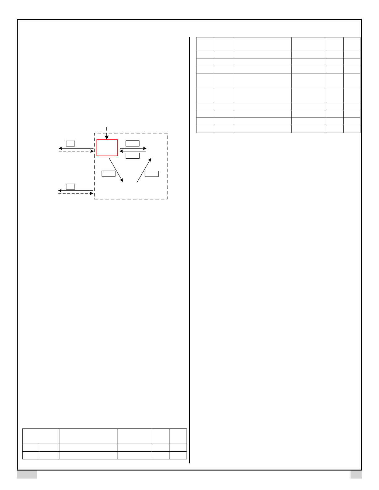
5. Mode Selection
This controller has 5 different modes: program run, program hold, program
stop, parameter setting, and programming mode. Before powering on the
controller, please connect the sensor cable to it. If no sensor is connected, the
controller will show error code “Err”, indicating no sensor is detected. When the
controller is powered on, it enters the Program Hold mode. It will flash
measured reading temperature value and “hold” alternatively. The controller
will start controlling temperature according to the saved setting, but the timer is
paused.
Program
Hold
Parameter
Setting Mode
Program
Run
Program
Stop
Programming
Mode
2 s
4 s
START
START
STOP
SET
PAUSE
Controller
Power Up
SET
Figure 2. Switching between different modes.
Program Running: The controller executes the saved program. The green
indicator RUN is lit, and the timer is running. The display window should show
the current temperature reading. The controller will send power to its
heating/cooling sockets to regulate temperature. When the program is running,
press PAUSE key will put the controller to Program Hold mode.
Program Holding: Controller pauses the time but it still regulates the
temperature at the current set value. The RUN indicator is off. The display
window flashes between the reading temperature and “Hold”. To resume the
program, press START key. To completely stop the program, hold the STOP
key for 4 seconds.
Program Stop: The execution of the program is terminated. Controller outputs
are deactivated and timer is also stopped. The RUN indicator is off. The display
window flashes between the reading temperature and “Stop”. To start the
program, press the START key. The controller will start regulating the program
from the first step.
Programming Mode: Review and edit temperature set value and set time for
each steps. When the controller is in Program Run, Hold, or Stop mode, press
SET key to enter the Programming mode. Please see Figure 4 for details.
Parameter Setting Mode: Review and edit system parameters. When the
controller is in Program Run, Hold, or Stop mode, hold the SET key for 2
seconds to enter the Parameter Setting mode. Please see Figure 3 for details.
6. Parameter Setup
Please see Table 2 for a list of parameters and see Figure 2 for the flow chart of
how to set the parameters. Please note that parameters will remain unchanged
unless you press set key to confirm the change.
Table 2. Parameters Description.
Code
Description
Setting
Range
Initial
Note
AH
AH
Deviation high alarm
0.5~999.9
20.0 1 AL
AL
Deviation low alarm
0.5~999.9
20.0
1
Hy
HY
Temp. Control Hysteresis
Band
0.5~99.9
1.0
2
CdF
CDF
Cooling Differential
0.5~99.9
5.0 3 HdF
HDF
Heating Differential
0.5~99.9
5.0 4 oFS
Ofs
Temp. Offset
-99.9~99.9
0
5
AS
AS
Anti-short Cycle Delay (only
for cooling socket)
M 0~ M99
(0~99 min)
M 0
6
A-M
A-M
Power Outage/Startup
Modes
S,M,C
S
7
PrG
PrG
Program Modes
on, off
ON 8 SFA
SFA
Sensor Failure Operation
0-0, 0-1, 1-0
0-0 9 Time
time
Time unit
H, M
H
10
C-F
C-F
Temperature unit
ºF, º C
ºF
11
Note 1. AH, deviation high alarm; AL, deviation low alarm:
Assuming measured temperature is PV and set temperature is C. When PV - C
is above AH, the built-in buzzer will turn on (deviation high alarm); when H –
PV is above AL, the built-in buzzer will turn on (deviation low alarm). User can
mute the alarm by momentarily pressing the Mute key. The alarm will remain
inactive until the process value moves out of the alarm zone. Both alarms are
deviation alarms, i.e., if AH = 20, AL = 30, and the Set Temperature (C) is 50F,
the alarm will be activated if the temperature is above 70F or below 20F. The
alarm function is suppressed at powering up or when the program is jumped
from one step to another step. It will be activated automatically once the
measured temperature enters the none-alarm zone (between C - AL and C +
AH).
Note 2. Hy, Temperature Control Hysteresis Band, or Temperature Control
Dead Band:
This parameter set up a dead band (between C - Hy and C + Hy) within which
either the heating device or cooling device will not work. The minimum value
for Hy is 0.5. The Hy value should not be too small if the system has sluggish
response. Otherwise, it may result in the heating device and the cooling device
working against each other, wasting energy and causing oscillation.
Note 3. CdF, Cooling Differential:
This is the differential band between turn on and turn off the cooling device. It
is set to the higher side of the temperature set point (C + Hy). The cooling
device will turn on when temperature is above (C + Hy + CdF), and turn off
when temperature is below (C + Hy). For compressor based cooling device, the
CdF value should not be set too small to prevent frequent cycling.
Note 4. HdF, Heating Differential:
This is the differential band between turn on and turn off the heating device. It
is set to the lower side of the temperature set point (C - Hy). The heating
device will turn on when temperature is below (C - Hy – HdF), and turn off
when temperature is above (C – Hy).
For example, if Set Temperature C = 50, Hy = 5, CdF = 3, HdF = 2, then the
heating device will turn on when process temperature is lower than 43 (C - Hy HdF) and turn off when process temperature rise above 45 (C - Hy). The
cooling device will turn on when process temperature is above 58 (C + Hy +
CdF) and turn off when process temperature drop below 55 (C + Hy).
Note 5. oFS, Temperature Offset:
oFS is used to compensate the error produced by the sensor or input signal
itself. For example, if the unit displays 37 when the actual temperature is 32.
Set parameter oFS = - 5 will make the controller display 32.The displayed
process temperature = actual measured temperature + oFS.
 Loading...