

Auber TD100 Instruction Manual
AUBER INSTRUMENTS WWW.AUBERINS.COM
Instruction Manual
TD100 TEMPERATURE CONTROLLER
INSTRUCTION MANUAL
1. Overview
This temperature controller contains one temperature probe and two
independent outputs. One output is for cooling device such as
refrigerator and the other one is for heating device. It can be used for
applications such as beer fermentation or convert a refrigerator to
kegerator. By using both cooling and heating devices, the refrigerator
can be controlled at specific temperature regardless in hot summer or
cold winter.
This controller is a plug and play controller. No wiring is needed for
the heater or cooler. Both the heating and cooling control modes are
simple on/off control, similar to a mechanical thermostat but with
much higher precision due to adjustable hysteresis band, precise
sensor and digital read out. Anti-short function is provided for cooling
to protect the compressor from being turned on with high pressure
Freon.
Different operation temperature ranges of the two outputs can be set
separately. Once the cooling range is set, the controller program will
automatically limit the heating range to prevent both heating and
cooling from being turned on at the same time.
A digital silicon band gap sensor is used . The advantage is being
much more reliable in moisture environment than thermistor sensor. It
can be immersed over extended period of time. It also has a more
uniform accuracy over an entire specified temperature range.
2. Specification
Temperature Control Range -50~125 °C, -58~257 °F
0.1 °C (between -9.9 ~ 99 °C)
Temperature Resolution
Temperature Accuracy 0.5 °C or 0.9 °F
Temperature Control Mode On/Off Control. Heating and Cooling
Temperature Control Output 10A, 120V or 240V AC *
Audio Alarm High and Low Limit
Sensor Ty pe Silicon Band Gap Sensor
Sensor Size 0.25" OD (6.35 mm) x 1" (25mm) long
Sensor Measuring Range -20~125 °C
Ambient Temperature -20~ 50 °C
Dimension 91x140x46mm
Input Power 85 ~242VAC, 50Hz/60Hz
Sensor Cable Length 3 ft (1m)
Power Cable Length 3 ft (1m)
Warranty 1 Year
1 °C (between -50 ~ 10 °C, 100~125°C)
0.1 °F (between -9.9~99.9 °F )
1 °F (between -58 ~ 10 °F,100 ~257 °F)
Version 1.1
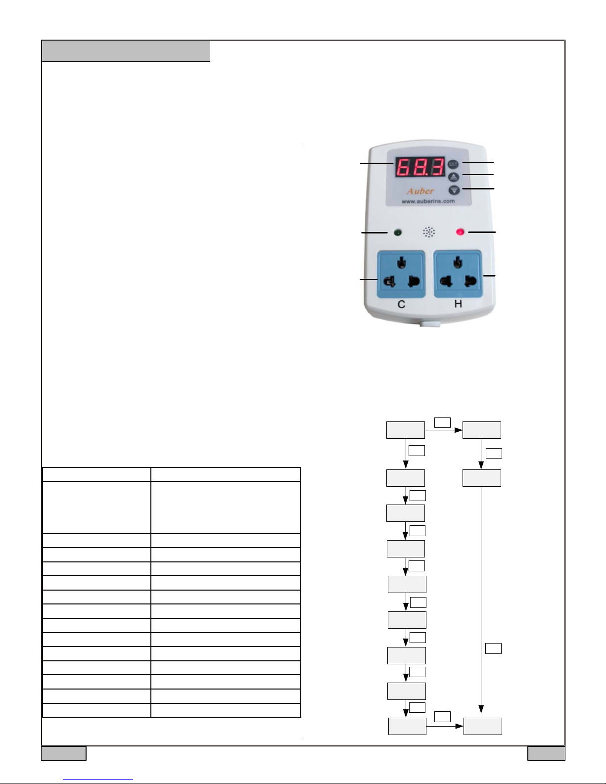
3. Front Panel
Measured
Temperature
Cooling Device
On Indicator
Cooling Device
Socket
Figure 1. Front Panel
Set Key
Up Key
Dn Key, Mute Alarm
Heating device
On Indicator
Heating Device
Socket
4. Setup Flow Chart
When the controller is powered on, it will display the measured
temperature. The controller will keep running according to the saved
setting. If the temperature sensor is shorted, the controller will display
“Err”. Please see Figure 2 for the flow chart to set the parameters.
SET
5 sec
SET
SET
SET
SET
SET
SET
SET
SET
SET
CSP
HSP
6 8.9
Cooling
Set Point
SET
Heating
Set Point
SET
Figure 2 Set
Up Flow Chart
Measured
Temperature
Alarm High Limit
Alarm Low Limit
Cooling Differential
Heating Differential
Cooling Antishort
Sensor Failure
Operation
Temperature Offset
Temperature Unit
6 8.9
AH
AL
CDF
HDF
AS
SFA
OFS
C-F
2013.05 P1/3
AUBER INSTRUMENTS WWW.AUBERINS.COM
5. Parameter Settings
To change the target temperature, press SET key momentarily. The
controller will show CSP (Cooling set point), press SET again will
show HSP (heating set point). When the controller shows CSP or
HSP, use Up or Down key to change the value. Then press SET key
to confirm the change.
To change the system parameters, press SET key for 5 seconds, the
controller will enter the parameter set up mode. The first parameter
AH will show on the display. Use Up or Down key to modify the
parameter value. Then press SET key to confirm the change. The
display will show the parameter again. Press the SET key to show
the ne x t p a r a me t e r . The instrument will automatically exit if no key is
pressed for 10 seconds. Please see the Table 1 for the parameters.
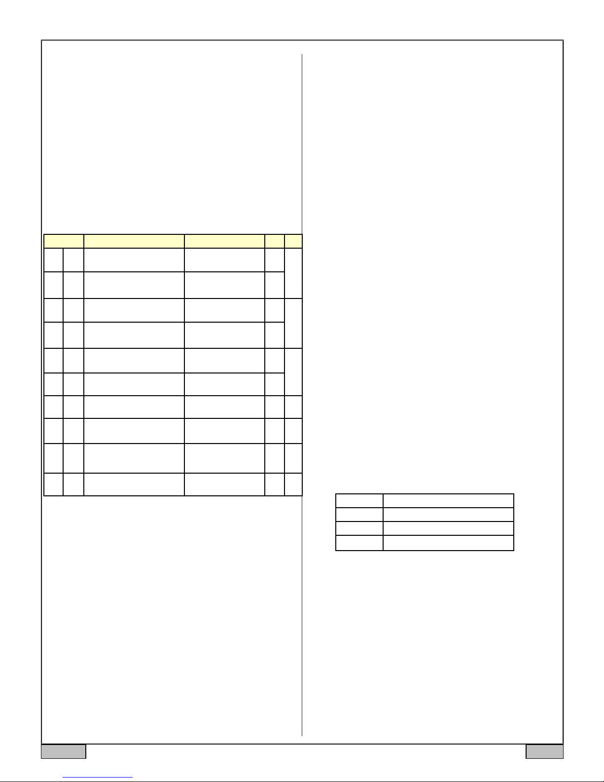
Table 1. Parameters Description
CSP
HSP
AH
AL
CdF
HdF
AS
SFA
oFS
Code
CSP
HSP
AH
AL
CDF
HDF
AS
SFA
OFS
Des cription S etting range Initial Note
C ooling Set Point
Heating Set Point
A l ar m High Li m it
A l ar m Low Lim i t
Cooli ng Differential 0~50.0 ºF 3.0
Heating Differntial 0~50.0 ºF 1.0
Cooling Antishort 0~12 mi n 0 3
S ensor F ai lure Operation 0-0, 0- 1, 1-0 0-0 4
Temperature Offset 0~10.0 0 5
-58~ 248 ºF
-50~125 ºC
-58~CS P ºF
-50~ CS P ºC
-58~ 248 ºF
-50~125 ºC
-58~ AH ºF
-50~A H ºC
67.0
62.0
95.0
32
Note 2. When the measured temperature is higher than AL, the high
limit alarm will be on; when the measured temperature is lower than
AL, the low limit alarm will be on.
When alarm is on, the display will be flashing between the measured
value and alarm type. To mute the alarm when it is on, press the
Down key momentarily. If the measured value gets out of the alarm
zone then gets back to the alarm zone again, the alarm will be on
again. To disable the alarm, set AH=AL.
The maximum value of the AL can be set is the current value of AH.
But AH can be set to the value between -58~248 ºF or
-50~125 ºC. When AH is set to a value lower than current AL, the AL
will be adjusted to the AH value automatically.
For example, when AH=95.0 ºF, AL=32 ºF, AL can be set to any
value between -58 and 95.0. For AH, it can be set to any value
between -58 and 248. If you set it to 25.0, the AL will be set to 25.0
1
automatically.
Note 3. The Cooling Antishort is the delay the time to turn the
coo l i ng load on .
2
compressor, it should not turn on the compressor when it is at high
pressure (just after turned off). Otherwise, It may shorten the life of
compressor. The Anti-Short cycle delay function can be used to
prevent the rapid cycling of the compressor. It establishes the
1
minimum time that the NO contacts remains open (after reaching
cutout) before closing again. The delay overrides any Load Demand
and does not allow the NO contacts to close until the set time-delay
value has elapsed. It gives time to release the refrigerant pressure
through evaporator. It is typically set to 4- 6 (minutes).
when the controller is used for cooling and load is a
Note 4. The SFA defines how the output would be if the sensor fails.
It can be set to 0-0, 0-1 or 1-0. Please refer to table 2 for details.
C-F
C-F
Temperature Unit
C : Celsius
F:Fahrenheit
F
Note 1. For cooling (or heating), the output will be off when the
temperature is blow (or over) the set point; will be on again when the
temperature rises up (or drops down) to CSP+CdF (or HSP-HdF).
Table 2. Output of the controller when sensor fails:
SFA Controller output when sensor fails
0-0 cooler off, heater off
1-0 cooler on, heater off
0-1 cooler off, heater on
For example, when the unit controls a refrigerator for food, you may
The maximum value of the HSP can be set is t he current value of
CSP. But CSP can be set to the value between -58~248 ºF or
-50~125 ºC. When the CSP is set to a value lower than current HSP,
want to set the TSF to ON if the sensor fails to keep th e food cold.
When it controls a heater, you may want to set th e ou tpu t to OFF fo r
safety purpose .
the HSP will be adjusted to the CSP value automatically.
For example, when CSP=67.0 ºF, HSP=62 ºF, HSP can be set to any
value between -58 and 67.0. For CSP, it can be set to any value
between -58 and 248. If you set it to 55.0, the HSP will be set to 55.0
automatically.
Small differential gives tight control; large differential reduces the
frequency of cycle on and off. It will extend the life of relay and
compressor.
Note 5. The offset is used to set an input offset to compensate the
error produced by the sensor or input signal itself.
For example, for temperature, if the unit displays 37 ºF when the
actual temperature is 32 ºF, setting parameter toF= - 5 will make the
controller display 32 ºF.
6. How to install the sensor to the unit.
The connector of sensor contains a slot for correct pin connection. It
also has a spring lock to prevent disconnections from accidental
pulling on the cable. To install the to the unit, please align the slot of
2013.05 P2/3
 Loading...