

Auber SYL-2342, SYL-2352 Instruction Manual
AUBER INSTRUMENTS WWW.AUBERINS.COM
2016.05 P1/8
SYL-2342 PID TEMPERATURE CONTROLLER
INSTRUCTION MANUAL
Version 5.3 (May 2016)
Caution
This controller is intended to control equipment under normal operating
conditions. If failure or malfunction of the controller may lead to abnormal
operating conditions that may result in personal injury or damage to the
equipment or other property, devices (limit or safety controls) or systems
(alarm or supervisory) intended to warn of or protect against failure or
malfunction of the controller must be incorporated into and maintained as
part of the control system.
Installing the rubber gasket supplied will protect the controller front panel
from dust and water splash (IP54 rating). Additional protection is needed for
higher IP rating.
This controller carries a 90-day warranty. This warranty is limited to the
controller only.
1. Specifications
Input type
Thermocouple (TC): K, E, S, N, J, T, B, WRe5/ 26;
RTD (Resistance Temperature Detector): Pt100, Cu50
DC Voltage: 0~5V, 1~5V, 0~1V, -100~100mV, 20~20mV, -5~5V, 0.2~1V
DC current: 0~10mA, 1~10mA, 4~20mA. (Use external
shunt resistor for higher current)
Input range
Please see section 4.7 for detail.
Accuracy
± 0.2% Full scale: RTD, linear voltage, linear current and
thermocouple input with ice point compensation or Cu50
copper compensation.
0.2% Full scale or ± 2 ºC: Thermocouple input with
internal automatic compensation.
Note: For thermocouple B, the measurement accuracy of
± 0.2% can only be guaranteed when input range is
between 600~1800 ºC.
Response time
≤ 0.5s (when FILt = 0)
Display resolution
1° C, 1°F; or 0.1° C
Control mode
Fuzzy logic enhanced PID control
On-off control
Manual control
Output mode
Relay contact (NO): 250VAC/7A, 120V/10A, 24VDC/10A
Alarm output
Relay contact (NO): 250VAC/1A, 120VAC/3A, 24V/3A
Alarm function
Process high alarm, process low alarm, deviation high
alarm, and deviation low alarm
Manual function
Automatic/Manual bumpless transfer
Power supply
85~260VAC/50~60Hz
Power
consumption
≤ 5 Watt
Ambient
temperature
0~50ºC, 32~122º F
Dimension
48 x 48 x 100mm (W x H x D)
Mounting cutout
45 x 45mm
2. Available Configurations
All the models listed in Table 1 are 1/16 DIN size with dual-alarm outputs.
Table 1. Controller models.
Model
Control output
Ramp/soak option
SYL-2342
Relay contact output
No
SYL-2342P
Relay contact output
Yes
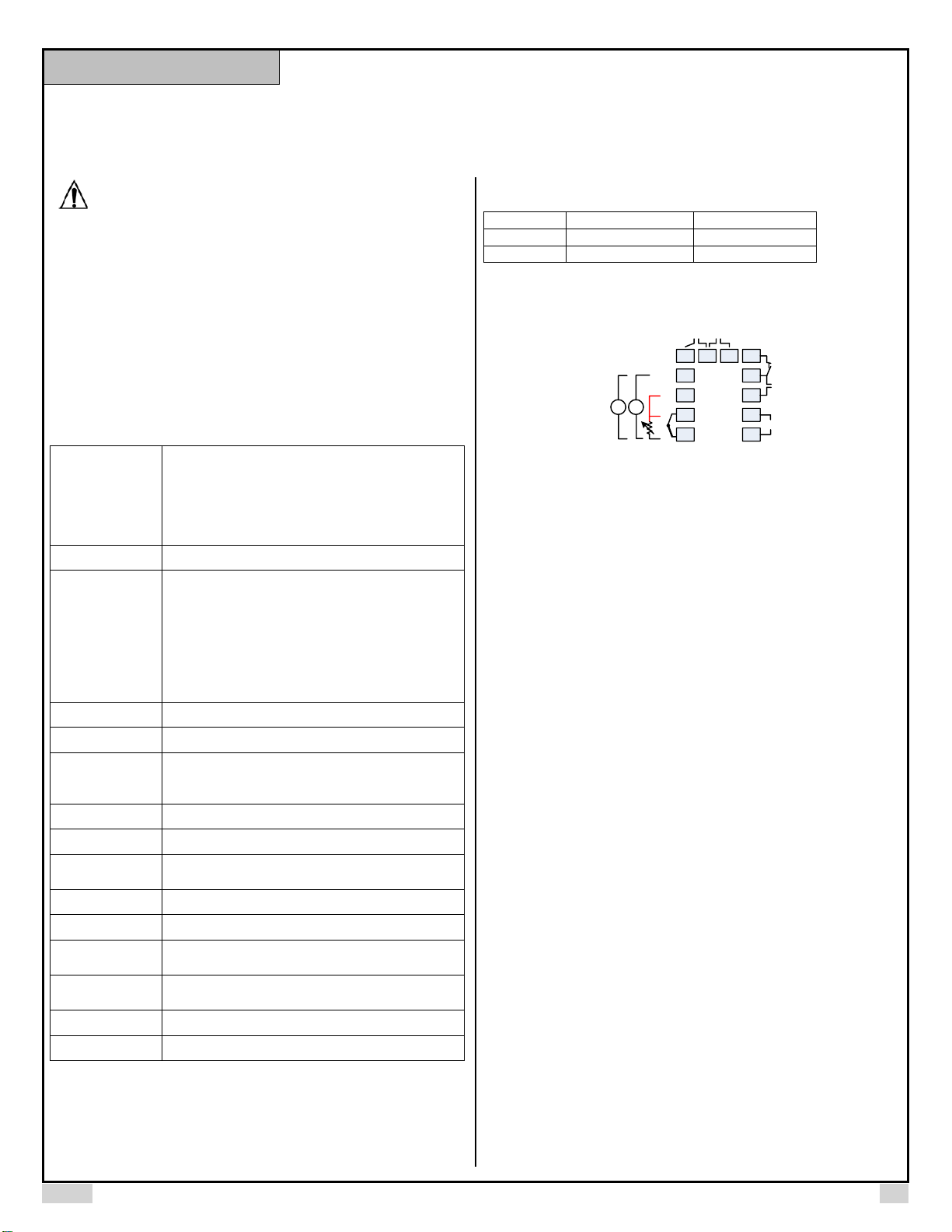
3. Terminal Wiring
1
2
3
13 14 6
7
8
9
10
4
5
RTD
R
R
W
TC
mA
V
AL1 AL2
AC
85~260V
Out
Model: SYL-2342, SYL-2342P
+
-
+
Figure 1. Wiring terminals of SYL-2342 and SYL-2342P.
3.1 Sensor connection
Please refer to Table 3 for the input sensor type (Sn) setting codes. The initial
setting for input is for a K type thermocouple. Set Sn to the right sensor code if
another sensor type is used.
3.1.1 Thermocouple
The thermocouple should be connected to terminals 4 and 5. Make sure that
the polarity is correct. There are two commonly used color codes for the K type
thermocouple. US color code uses yellow (positive) and red (negative).
Imported DIN color code uses red (positive) and green/blue (negative). The
temperature reading will decrease as temperature increases if the connection
is reversed.
When using ungrounded thermocouple that is in touch with a large conductive
subject, the electromagnetic field picked up by the sensor tip might be too large
for the controller to handle, the temperature display will change erratically. In
that case, connecting the shield of thermocouple to terminal 5 (circuit ground of
the controller) might solve the problem. Another option is to connect the
conductive subject to terminal 5.
3.1.2 RTD sensor
For a three-wire RTD with standard DIN color code, the two red wires should
be connected to the terminals 3 and 4. The white wire should be connected to
terminal 5. For a two-wire RTD, the wires should be connected to terminals 4
and 5. Jump a wire between terminals 3 and 4. Set controller input type, Sn to
21.
3.1.3 Linear input (V, mV, mA or resistance)
V and mA current signal inputs should be connected between terminals 2 and
5. Terminal 2 is positive. mV signal inputs should be connected between
terminals 4 and 5. Terminal 4 is positive. For resistance inputs, short terminals
3 and 4, then connect resistance inputs between terminals 4 and 5.
3.2 Power to the controller
The power cables should be connected to terminals 9 and 10. Polarity does not
matter. It can be powered by 85-260V AC power source. Neither a transformer
nor jumper is needed to wire it up. For the sake of consistency with the wiring
example described later, we suggest you connect the hot wire to terminal 9 and
neutral to 10.
Instruction Manual
AUBER INSTRUMENTS WWW.AUBERINS.COM
2016.05 P2/8
3.3 Control output connection
The relay output of the controller SYL-2342 can be used to turn on a contactor
or a solenoid valve. It can drive a small heater directly if the heater draws less
than 10A when connected to 120V AC power source. For applications needing
two control outputs, such as one for heating and another for cooling, relays
AL1 or AL2 can be used for the second output with on/off control mode. Please
see Figure 11 for details.
3.3.1 Connecting the load through a contactor
Assuming the controller is powered by 120V AC and the contactor has a 120V
AC coil, jump a wire between terminals 8 and 9. Connect terminal 7 to one lead
of the coil and terminal 10 to the other lead of the coil. Please see Figure 7 for
example.
3.3.2 Connecting the heater (or cooler) directly from the internal relay
Assuming the controller and the load (heater or cooler) are powered by the
same voltage. Jump a wire from terminal 9 to 8. Connect terminal 7 to the one
lead of the load and terminal 10 to the other lead of the load. Please see Figure
6 and 9 for details.
3.4 For first time users without prior experience with PID controllers, the
following notes may prevent you from making common mistakes.
3.4.1 Power to the heater does not flow through terminal 9 and 10 of the
controller. The controller consumes less than 2 watts of power. It only provides
a control signal to the relay. Therefore, wires in the 18 to 26 gauge range
should be used for providing power to terminals 9 and 10. Thicker wires may
be more difficult to install.
3.4.2 The control relay outputs (for SYL-2342), AL1 and AL2, are “dry” single
pole switches. They do not provide power by themselves. Please see Figure 6,
7 and 11 for how they are wired when providing a 120V output (or when output
voltage is the same as the power source for the controller). If the load of the
relay requires a different voltage than that for the controller, another power
source will be needed. See Figure 8 for examples.
3.4.3 For all controller models listed in this manual, the power is controlled by
regulating the duration of on time for a fixed period of time. It is not controlled
by regulating amplitude of the voltage or current. This is often referred as time
proportional control. For example, if the cycle rate is set for 100 seconds, a 60%
output means controller will switch on the power for 60 seconds and off for 40
seconds (60/100 = 60%). Almost all high power control systems use time
proportional control because amplitude proportional control is too expensive
and inefficient.
4. Front Panel and Operation
3
4
5
6
1
2
7 8 9 10
8 8 8 8
8 8 8 8
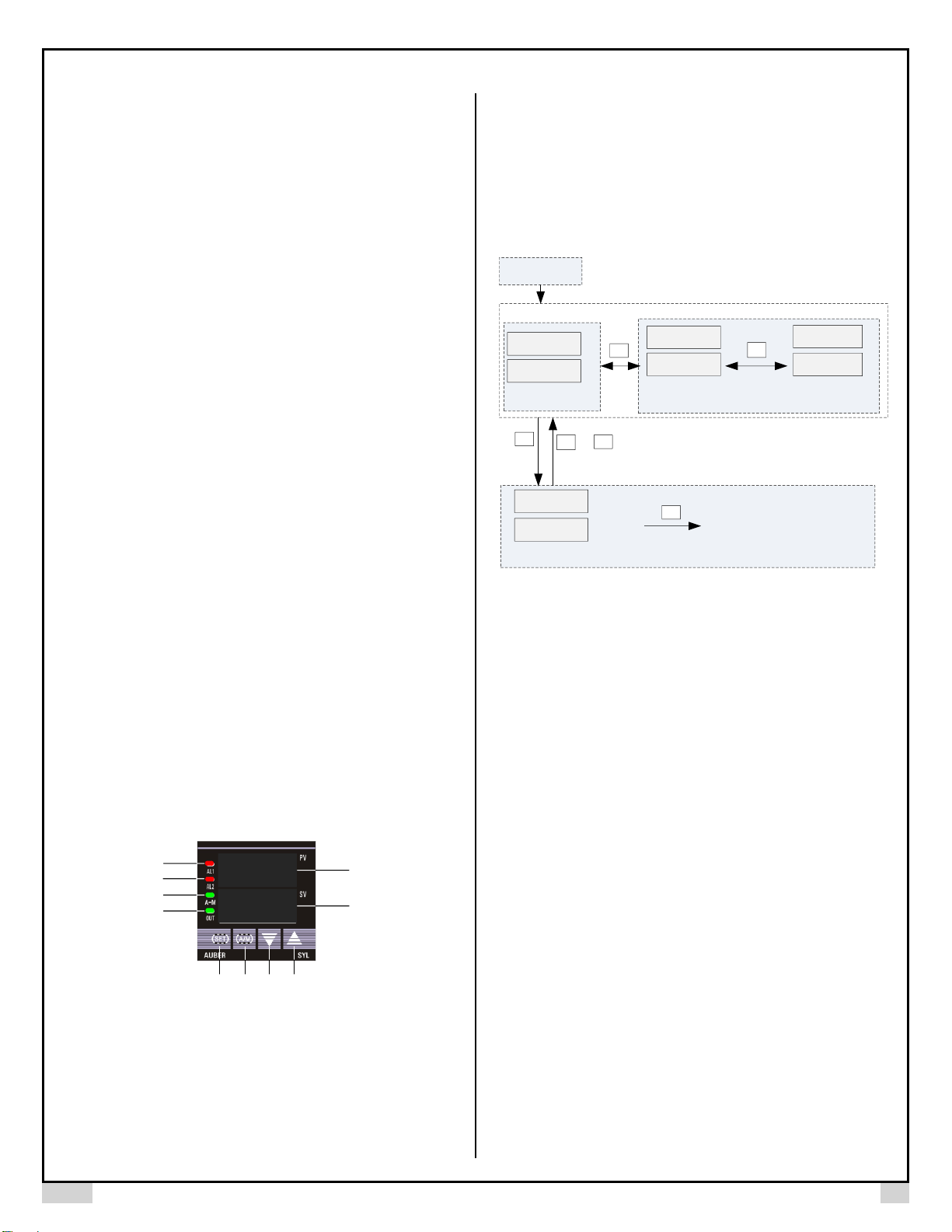
Figure 2. Front panel
① PV display: Indicates the sensor read out, or process value (PV).
② SV display: Indicates the set value (SV) or output value (%).
③ AL1 indicator: It lights up when AL1 relay is on.
④ AL2 indicator: It lights up when AL2 relay is on.
⑤ A-M indicator: The light indicates that the controller is in manual mode. For
the controllers with the Ramp/Soak option, this light indicates that the
program is running.
⑥ Output indicator: It is synchronized with control output (terminal 7 and 8),
and the power to the load. When it is on, the heater (or cooler) is powered.
⑦ SET key: When it is pressed momentarily, the controller will switch the
lower (SV) display between set value and percentage of output. When
pressed and held for two seconds will put the controller into parameter
setting mode.
⑧ Automatic/Manual function key (A/M) /Data shift key.
⑨ Decrement key ▼: Decreases numeric value of the setting value.
⑩ Increment key ▲: Increases numeric value of the setting value.
4.1 Display Status
Power on
8 0 0.0
8 0 0.5
Display mode 1
8 0 0.0
A 6 0
8 0 0.0
“M 60” means
output value=60%
on manual mode
Display mode 2
1 0 0 5
ALM1 (high limit alarm)=1005
Display mode 3
2S
+
Next parameter
M 6 0
A L M1
SET
SET
SET
A/M
SET
A/M
“A 60” means
output value=60%
on Automatic mode
PV
SV
PV
PV
Figure 3. Display modes
Display mode 1: When the power is turned on, the upper display window
shows the measured value (PV) and the lower window shows the four-digit set
value (SV).
Display mode 2: Press the SET key to change the display status into mode 2.
The upper display window shows the measured value (PV) and the lower
windows shows the output value. This picture shows the output percentage is
60% when in Automatic (PID) control mode. If parameter A-M = 1 (see table 2),
pressing the A/M key will switch the controller between PID and Manual control
mode with the output unchanged. This bumpless transfer allows the controller
to be switched between manual and automatic mode without the output
suddenly 'bumping' to a different value.
Display mode 3: Press the SET key for 2 seconds to enter the display mode 3.
This mode allows users to change the system parameters.
4.2 Basic Operation
4.2.1 Changing set value (SV)
Press the ▼ or ▲ key once, and then release it. The decimal point on the
lower right corner will start to flash. Press the ▼ or ▲ key to change SV until
the desired value is displayed. If the change of SV is large, press the A/M key
to move the flashing decimal point to the desired digit that needs to be
changed. Then press the ▼ or ▲ key to start changing SV from that digit. The
decimal point will stop flashing after no key is pressed for 3 seconds. The
changed SV will be automatically registered without pressing the SET key.
4.2.2 Display change
Press the SET key to change the display mode. The display can be changed
between display modes 1 and 2.
AUBER INSTRUMENTS WWW.AUBERINS.COM
2016.05 P3/8
SET
PV
SV
2S
SET
SET
SET
SET
SET
SET
SET
ALM1
Process high alarm
HY-1
9 9 9 9
Hy-1
Deviation high alarm
HY-2
9 9 9 9
Hy-2
Deviation low alarm
HY
0.3
Hy
Hysteresis band
AT
3
At
Control mode
I
1 0 0 0
I
Integral time
P
5 0 0
P
Proportional constant
SET
SET
SET
SET
SET
SET
SET
SET
t
2
t
Cycle time
SN
0
Sn
Input type
DP
0
dP
Decimal point position
Baud
9 6 0 0
Baud
Communication baud
filt
0
FILT
PV input filter
A-M
2
A-M
Running status
SET
SET
SET
SET
SET
SET
SET
SET
P-SH
2 5 0 0
P-SH
Display high limit
Pb
0.0
Pb
Input offset
Op-A
0
OP-A
Output mode
outL
0
OutL
Output low limit
OUtH
1 0 0
OutH
Output high limit
AL-P
1 7
AL-P
Alarm output definition
COOL
1 0
Cool
System function selection
Addr
1
Addr
Communication address
d
1 2 0
d
Derivative time
P-SL
- 1 0 0
P-SL
Display low limit
SET
SET
EP1-EP8
ALM1
1 0 0
ALM2
5 0
ALM2
Process low alarm
Locw
8 0 8
Lock
Configuration privilege
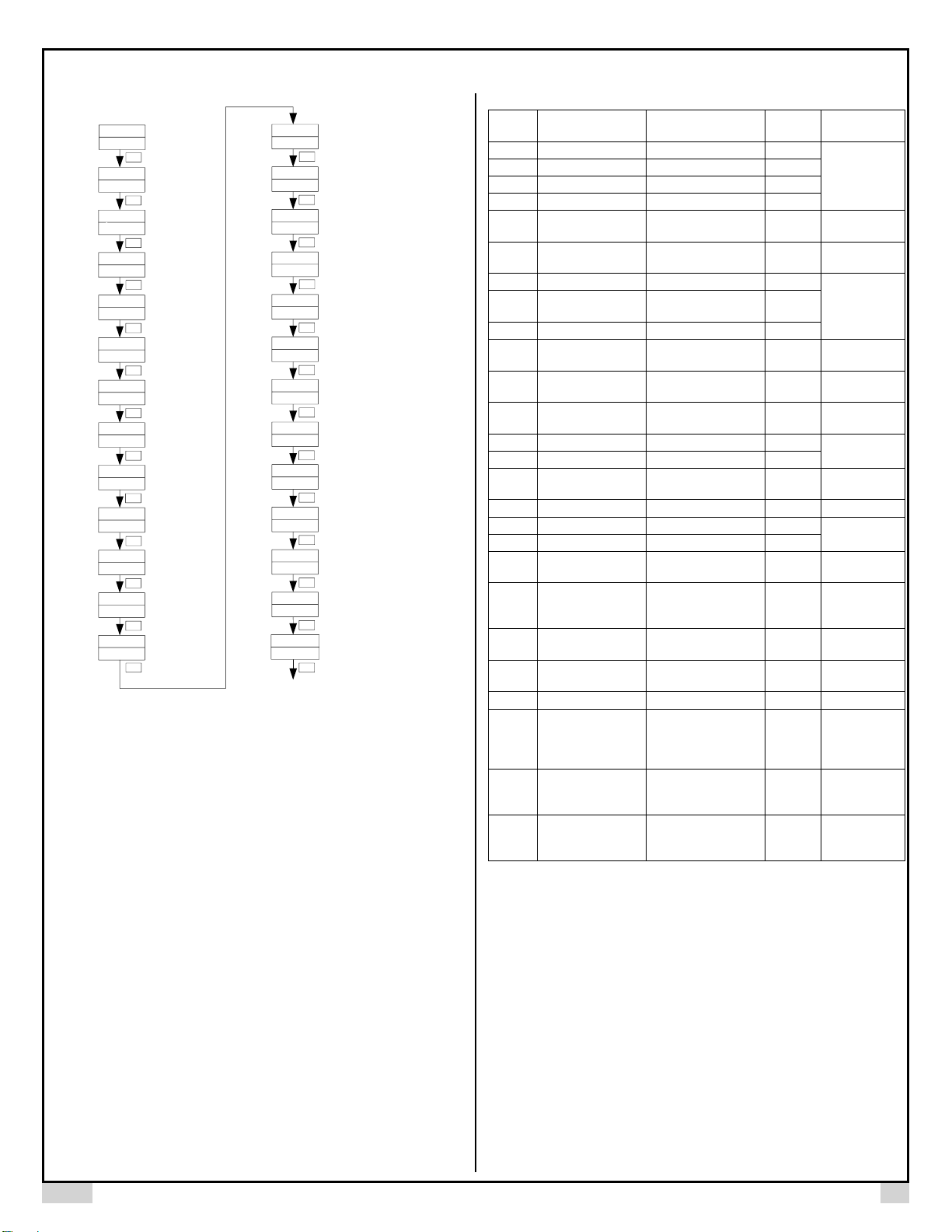
Figure 4. System setup flow chart
4.2.3 Manual/Automatic mode switch
Bumpless switching between PID mode and Manual mode can be performed
by pressing the A/M key. The A-M LED will light up when the controller is in
Manual mode. In Manual mode, the output amplitude can be increased or
decreased by pressing ▲ and ▼ (display mode 2). Please note that manual
control is initially disabled (A-M = 2). To activate the manual control, set
A-M = 0 or 1.
4.2.4 Parameter Setup Mode
When the display mode is 1 or 2, press SET and hold for roughly 2 seconds
until the parameter setup menu is displayed (display mode 3). Please refer to
4.3 for how to set the parameters.
4.3 Setup flow chart
While in the parameter setup mode, use ▲ and ▼ to modify a digit and use
A/M to select the digit that needs to be modified. Press the A/M and SET key at
the same time to exit the parameter setup mode. The instrument will
automatically exit if no key is pressed for 10 seconds. Figure 4 is the setup flow
chart. Please note the changed parameter will be automatically registered
without pressing the SET key. If the controller is locked (see 4.17). Only limited
parameters (or no parameters) can be changed.
4.4 Parameter Setting
Table 2. System parameters.
Code
Description
Setting Range
Initial
Setting
Remarks
ALM1
Process high alarm
-1999~+9999° C or °F
100
See 4.4.1
ALM2
Process low alarm
-1999~+9999° C or °F
50
Hy-1
Deviation high alarm
0~+9999° C or °F
9999
Hy-2
Deviation low alarm
0~+9999° C or °F
9999
Hy
Hysteresis Band
0~200° C or ° F or
0~2000 for linear input
0.3
See 4.4.2
At
Auto tuning
0~3. Set to 1 or 2 to
start Auto tuning
3
See 4.4.3
I
Integral time
0~9999
1000
See 4.5.1
P
Proportional
Constant
1~9999%
500
d
Derivative Time
0~2000
120
t
Cycle time
2~125
20 for
relays
See 4.6
Sn
Input type
0~37
0 (K type
TC)
See 4.7
dP
Decimal point
position
0~3
0
See 4.8
P-SL
Display low limit
-1999~+9999° C or °F
-100
See 4.9
P-SH
Display high limit
-1999~+9999° C or ° F
2500
Pb
Input offset
-1999~+4000
-1999~+9999° C or °F
0.0
See 4.10
OP-A
Output mode
0~2
0
See 4.11
OUTL
Output low limit
0~100%
0
See 4.12
OUTH
Output high limit
0~100%
100
AL-P
Alarm output
definition
0~31
17
See 4.13
COOL
System function
selection
0~15
10
For heating
and ° F display,
see 4.14
Addr
Communication
address
s 0~20
1
Ignore this
setting
bAud
Communication baud
rate
0~19200
9600
Ignore this
setting
FILt
PV input filter
0~20
0
See 4.15
A-M
Automatic/Manual
status
0. Manual
1. Automatic
2. Manual suppressing
2
Manual control
is disabled. Set
to 1 to active.
See 4.16
LocK
Configuration
privilege
0~9999
808
All parameters
are unlocked.
See 4.17
EP1-
EP8
Field parameter
definition
nonE ~ A-M
nonE
To be defined
by user. See
4.17
4.4.1 Alarm parameters
This controller offers four types of alarm, “ALM1”, “ALM2”, “Hy-1”, “Hy-2”.
ALM1: High limit absolute alarm. If the process value is greater than the
value specified as “ALM1+Hy” (Hy is the Hysteresis Band), then the alarm
will turn on. It will turn off when the process value is less than “ALM1-Hy”.
ALM2: Low limit absolute alarm. If the process value is less than the value
specified as “ALM2-Hy”, then the alarm will turn on, and the alarm will turn
off if the process value is greater than “ALM2+Hy”.
Hy-1: Deviation high alarm. If the temperature is above “SV+Hy-1 +Hy”, the
alarm will turn on, and the alarm will turn off if the process value is less than
“SV+Hy-1 -Hy” (we will discuss the role of Hy in the next section)
Hy-2: Deviation low alarm. If the temperature is below “SV-Hy-2 -Hy”, the
alarm will turn on, and the alarm will turn off if the temperature is greater
than “SV-Hy-2 +Hy”.
 Loading...