

Auber SYL-1615 Instruction Manual
AUBER INSTRUMENTS WWW.AUBERINS.COM
Instruction Manual
SYL-1615 Temperature Controller for Charcoal Smoker
Version 1.1
1. Features
This PID controller is for controlling the temperature of charcoal smoker. It will regulate
the on/off time interval of a 12VDC blower to stabilize the temperature in the charcoal
smoker. It has built-in solid state relay that can drive a 12V DC operated blower up to
60 CFM. It has a built-in buzzer that can be set for both low limit and high limit alarm.
The system includes a controller, an AC to 12V DC adaptor, a K type thermocouple.
Also included is power plug that fits the control output jack. User needs to install the
plug to a 12V DC operated blower with adequate wind speed (5 CFM Fan is the most
common for a small smoker).
2. Specifications
AC adaptor: 100-240V, 50/60Hz input. 12 VDC, 1 Amp output.
Power consumption: <2W
Sampling rate: 4 samples/second
Accuracy: 0.2% full scale
Display range: -320~2400°F, or -200~1300°C
SSR output for Fan: 12VDC, 1 Amp*
LED display: 0.39 inch, red
Control Mode: PID, On/off, Limit.
Alarm: Two set points with buzzer sound.
Sensor: K type thermocouple, -300~550°F (-200~300°C).**
Dimension: 2.8x3.5x1.2" (70x90x30mm)
* Up to 3 Amp can be supplied when more powerful power supply is used.
** Eight other types of thermocouple can also be accepted (see table 4)
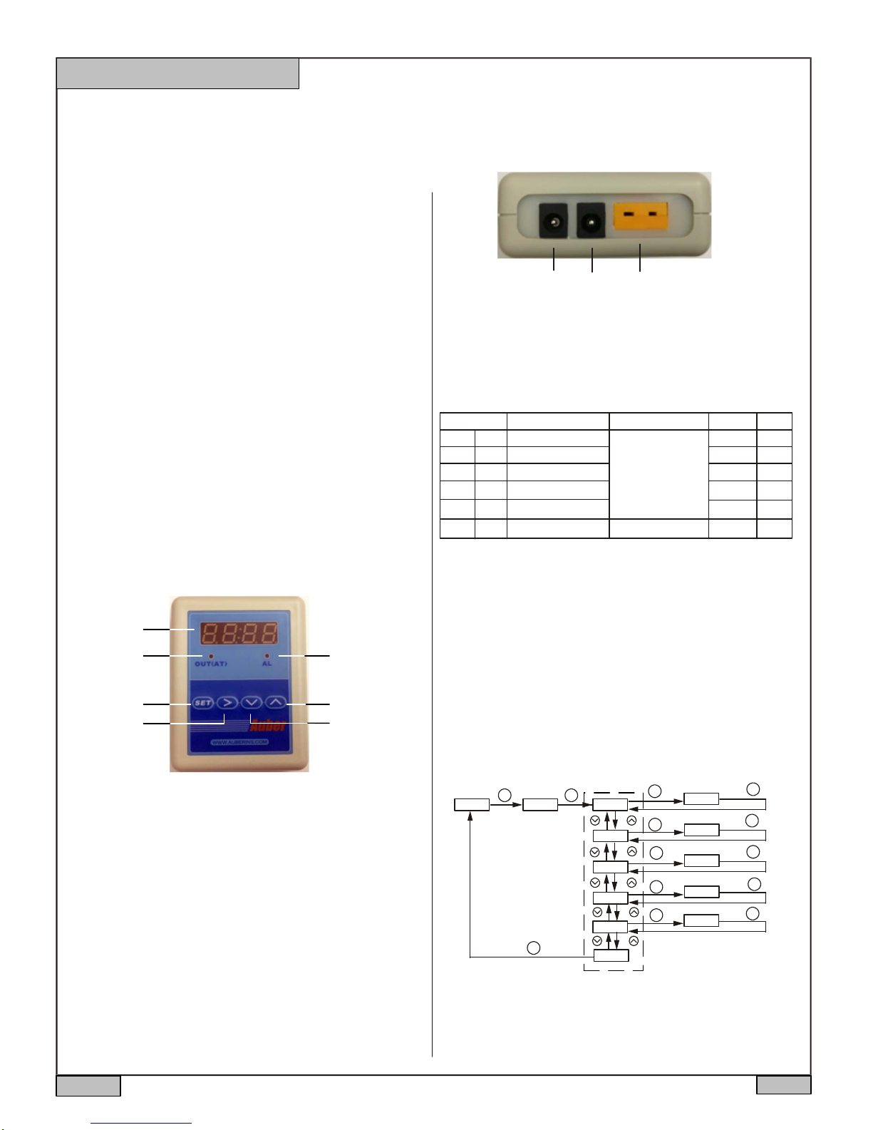
3. Front Panel
①
②
③
④ ⑤
⑦
⑥
①
②
③
① POWER-12V Power supply input
② OUT- Fan control output
③ INPUT-Temperature probe input
Figure 2. Terminals (back view)
5. Parameter Setting
5.1. Temperature setting and Alarm setting (accessed by code 0001)
Table 1. Temperature and alarm parameters
Symbol
SV
AH1
AH1
AL1
AL1
AH2
AL2
AL2
End
End
Note 1. Set Temperature.
There are two ways to set the target temperature.
a. During the normal operation mode, press Λ or V once to switch the display from
process value (PV) to set value (SV, or target temperature). The display will start to
blink. Press Λ or V again to increase or decrease the SV. When finished, wait 8
seconds and the settings will take effect automatically (the display will stop blinking).
b. Press SET key once. Use >, Λ and V keys to enter code 0001. Press SET key to
confirm, then the display would be SV (Su). Press SET key again to display the SV
setting. Use >, Λ and V keys to enter the new SV value and press SET to confirm.
Press V key to change the display to END. Then, press SET to exit. You can also
ignore the steps after confirmation of SV. The controller will return to normal operation
mode automatically if no key is pressed for 1 minute. The flow chart below shows how
to set the SV and alarms in details.
Description
Target temperature
SV
Alarm 1 on temperature
Alarm 1 off temperature
Alarm 2 on temperature
AH2
Alarm 2 off temperature
Exit
Range
Arbitrary value
within the
measuring range
Initial
200
250
249
250
250
Note
Note 1
Note 2
Figure 1. Front panel
Parameter display
①
② OUT-SSR output indicator
(AT)-Blinking during auto-tune process
③ Set/Confirm
④ Digit shift/Alarm mute/Auto-tune
⑤ Value decrement/Select previous parameter
⑥ Value increment/Select next parameter
⑦ AL-Alarm Indicator
4. Connecting the Controller
Figure 2 shows the terminals of the controller. Connect the AC to 12V DC power
adapter to the terminal 1 and wall outlet. Connect the fan connector to terminal 2. The
polarity for this socket is center pin positive (+), outer collar negative (−). Connect the
K thermocouple to terminal 3. Please note that thermocouple connector also has
polarity. The wide blade should go to the wide slot.
2013.05
Operation Mode
XXXX
Enter Code
SET SET
0001
Parameter Display
sv
Target Temp Selection
SET
SET
ah1
SET
al1
ah2
SET
SET
al2
SET
end
Figure 3. Flow chart for how to set target temperature and alarm.
0200
Buzzer On Temp
0250
Buzzer Off Temp
0249
Buzzer On Temp
0250
Buzzer Off Temp
0250
SET
SET
SET
SET
SET
P1/3
AUBER INSTRUMENTS WWW.AUBERINS.COM
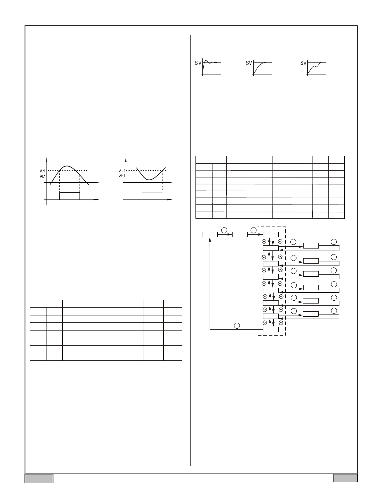
Note 2. Set alarm
The controller offers two alarms that can be set to turn on the buzzer at specific
temperatures. The first alarm is controlled by parameters AH1 and AL1. The initial
setting will turn on the buzzer at 250°F and off when temperature drops below 249°F.
The second alarm is controlled by parameters AH2 and AL2. The initial setting of the
second alarm is deactivated. It can be set as low alarm to send warning when
charcoal is low.
AH1 and AH2 are the temperatures to turn buzzer on; AL1 and AL2 are the
temperatures to turn buzzer off. When AH1(2) >AL1(2), the alarm is set for absolute
high alarm as shown in Figure 4 below. When AH1(2) <AL1(2), the alarm is set for
absolute low alarm as shown in Figure 5 below. When AH1(2)=AL1(2), the alarm is
deactivated.
Example, if AH1=250, AL1=249, when the temperature goes up to 250°F, the buzzer
will be on; when the temperature drops down to 249°F, the buzzer will be off. If
AH2=180, AL2=185, when the temperature drops down to 180°F, the buzzer will be
on; when the temperature goes up to 185°F, the buzzer will be off.
User can press the shift key (>) to temporarily mute the buzzer sound. The alarm will
buzz again if the alarm set temperature is reached again. To permanently deactivate
the alarm, set AH1=AL1 or AH2=AL2. Please see flow chart in Figure 3 on how to set
the value.
PV
Buzzer on Buzzer on
PV
Figure 4. Absolute high alarm Figure 5. Absolute low alarm
The contents below are for reference and advanced applications. Most BBQ
smoker users do not need to read beyond this point.
5.2 PID parameter setting (accessed by code 0036)
The values of P, I and D parameters are critical for good response time, accuracy and
stab ility of the system. The values of the PID parameters have been optimized for
charcoal grill application. User should not change it unless the result is not satisfactory.
In that case, you can use the Auto-Tune function to automatically determine these
parameters. If auto-tuning result is not satisfactory, you can manually fine-tune the PID
constants for improved performance.
Setting PID parameters is similar to the setting of the Temperature and Alarm
Parameter as shown in the flow chart of Figure 3. The difference is that these
parameters are accessed by enter code 0036 instead of 0001.
Table 2. PID and relevant parameters
Symbol
p
i
d
souf
SouF
ot
ot
filt
FILt
End
end
Note 3. Proportional Constant (P): When P increases, the system is more stable.
When P decreases, the system is less stable. If the P is too small, the system would
be oscillatory or even non-convergent.
Note 4. Integral time (I): Brings the system up to the set value by adding a constant to
the output that is proportional to how far the process value (PV) is from the set value
(SV) and how long it has been there. When I decreases, the response speed is faster
but the system is less stable. When I increases, the respond speed is slower, but the
system is more stable. When I is 0, then it turns to be PD control.
Note 5. Derivative time (d): Responds to the rate of PV change, so that the controller
can compensate in advance before |SV-PV| gets too big. A larger number increases
it’s action. Setting d-value too small or too large would decrease system stability,
cause oscillation or even non-convergence.
Description
Proportional Constant
P
Integral Time
I
Derivative Time
d
Damp Constant
Cycle Rate
Digital Filter Strength
Exit
Setting Range Initial
0.1~99.9(%)
2~1999(Sec)
0~399(Sec)
0.1~1.0
2~199(Sec)
0~3
Note
1.2
300
70
0.7
15
Note 3
Note 4
Note 5
Note 6
Note 7
Note 8
0
Note 6. Damp constant (SouF): The parameter is controlled by the artificial
intelligence of the controller. This constant helps the PID control quality. When its
value is too high, the system will be over damped. When its value its too low, the
system may overshoot.
SouF too low
SouF acceptable
SouF too high
Figure 6. Damp constant
Note 7. Cycle rate (ot): It is the time period that the controller uses to calculate its
ou t put . The initial value is set to 15 seconds for charcoal smoker control. Short time
causes the fan to pulse at higher frequency. Longer time may reduce the quality of
control
Note 8. Digital Filter (Filt): can be set as 0, 1, 2, 3. Filt=0, filter diabled; Filt=3, strongest
filtering effect. Stronger filtering increases the stability of readout display, but causes
more delay in the response to changes in temperature.
5.3 System Configuration Parameters (accessed by code 0089)
Table 3. System configuration parameter setting
Code Setting Range
inty
Inty
outy
outy
Hy
hy
atdu
Atdu
psb
PSb
rd
rd
corf
CorF
end
End
Operation Mode
XXXX
Description
Input Sensor Type
Control Output Mode
Hysteresis Band
3
0, 1, 2, 3, 4, 5, 6
Autotune Offset
Input Offset
Control Function
0: heating 1: Cooling
Display Unit
Exit
Parameter Display
Enter Code
SET SET
0089
inty
outy
HY
atdu
psb
rd
corf
SET
end
See Appendix
0~9999
0~200
-1000~1000
0: °C 1:°F
Output mode selection
SET
Hysteresis Band
SET
Autotune offset
SET
SET
Heating/Cooling
SET
Display Unit(C/F)
SET
XXXX
Input offset
XXXX
X
X
X
X
Initial Note
K
Note 9
2
Note 10
10
Note 11
0
Note 12
Note 13
0
Note 14
1
SET
SET
SET
SET
SET
SET
Figure 7. The system setup flow chart
Note 9. The value of outy determines the control mode: When it is set to,
2: PID control mode.
3: On/off control mode.
6: Limit control mode.
Setting value for 0, 1, 4, 5 should not be used for this controller.
The new outy setting will not take effect if the outy is changed until the controller is
restarted .
Note 10. Hy is only used when controller is in on/off or limit control mode. It sets the
hysteresis band for the controller.
Note 11. The auto-tune offset will shift the SV value down by the Atdu value during the
auto tune process. It will prevent the system from damage due to overheating during
auto-tuning.
Note 12. Calibration offset, PSb is used to set an input offset to compensate
the error produced by the sensor. For example, if the meter displays 5 ºC
when probe is in ice/water mixture, setting PSb=-5, will make the controller
display 0 ºC. To set negative value, shift to the very left digit, press down key until it
shows “-“.
Note 13. Rd is for system function selection, 1 for cooling, 0 for heating.
2013.05
P2/3
 Loading...