

Auber SWA-2451A Instruction Manual
AUBER INSTRUMENTS WWW.AUBERINS.COM
2019.01 P1/6
SWA-2451A PID TEMPERATURE CONTROLLER INSTRUCTION MANUAL
Version 1.0 (Jan, 2019)
1. Caution
• This controller is intended to control equipment under normal operating
conditions. If failure or malfunction of the controller may lead to abnormal
operating conditions that may result in personal injury or damage to the
equipment or other property, devices (limit or safety controls) or systems
(alarm or supervisory) intended to warn of or protect against failure or
malfunction of the controller must be incorporated into and maintained as
part of the control system.
• Installing the rubber gasket supplied will protect the controller front panel
from dust and water splash (IP54 rating). Additional protection is needed for
higher IP rating.
• This controller carries a 90-day limited warranty. This warranty is limited to
the controller only.
2. Specifications
Table 1. Specifications
Input Type
Thermocouple: K, E, J, T, S. RTD: Pt100, Cu50
Input Range
K (-20~2370ºF), S (-20~2912º F), T (-190~750º F),
E (-20~1290ºF), J (-20~1651º F), Pt100 (-200~1100º F)
Cu50 (-56~302)
Display
Two lines, four digits. Temperature & time or
temperature & set temperature.
Display
Resolution
Temperature: 1° C/°F and 0.1° C/ ° F
Time: 1 second/ minute.
Accuracy
Temperature: ± 0.5% of full input range.
Time: 1 second.
Control Mode
Temperature: PID, manual control, on-off,
Time: timed PID, timed on-off, independent timer
Timer Mode
Single delay, double delay, count up, count down
Timer Range
1 - 9999 seconds or minutes
Anti-Short Cycle
Delay Timer
Range
1 - 200 minutes
Control Output
SSR control output: 12 VDC, 50 mA
Alarm
Timer alarm, process high/low alarm, deviation
high/low alarm
Alarm Output
Relay: 3 A at 240 VAC, 5 A at 120 VAC, or 3 A at 30
VDC
Power Supply
90 ~ 265 VAC, 50 ~ 6 0Hz
Dimension
1.89 x 1.89 x 4.25", or 48 x 48 x 108 mm (1/16 DIN)
Insertion Depth
From front panel: 3.95" or 100 mm
Panel Cutout
1.75 x 1.75" or 44.5 x 44.5 mm
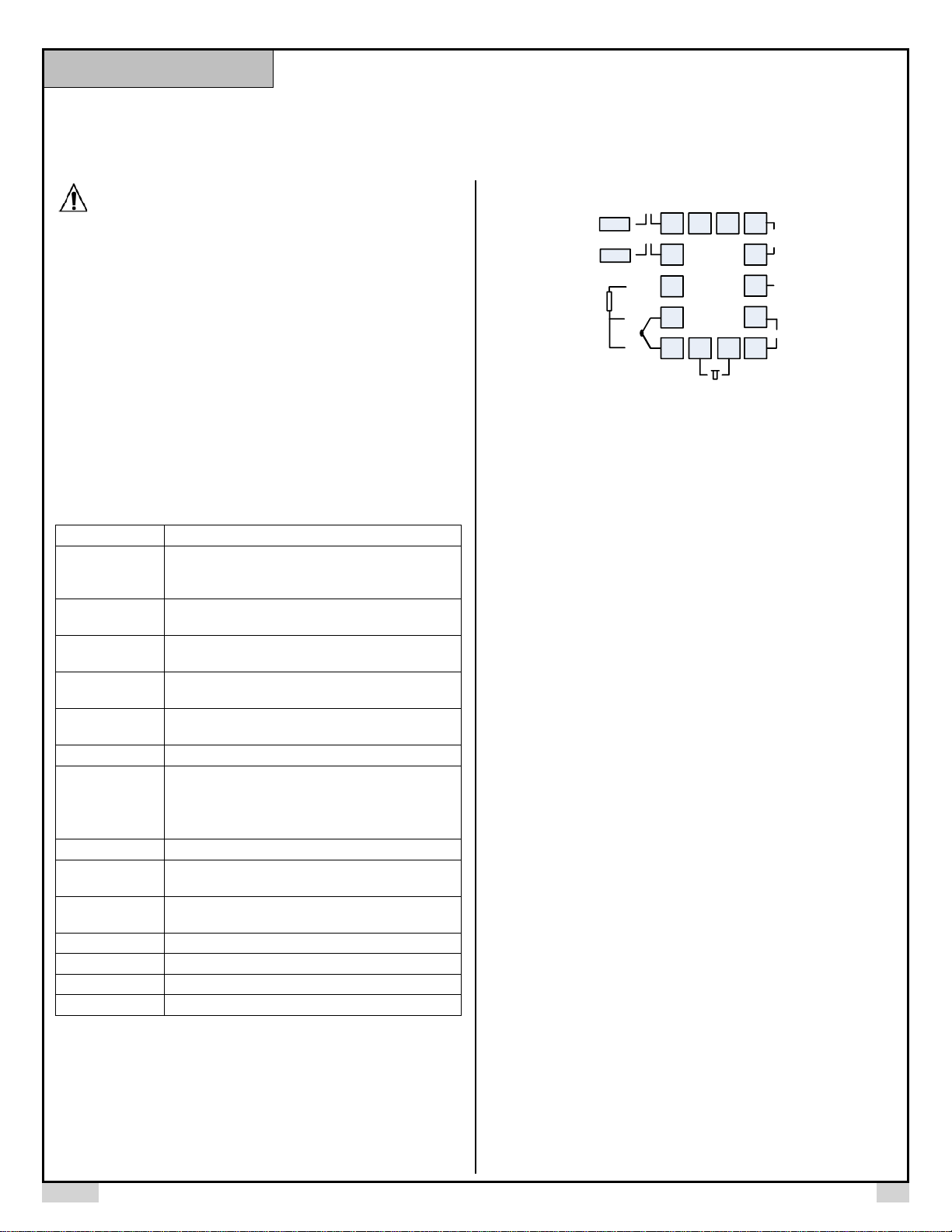
3. Terminal Assignment
TC
1
2
13 14 6
7
8
9
105
SSR out
11 12
+
_
input
85-260VAC
3
4
W
R
+
-
R
RTD
COM
(AL 1/ AL2)
To 8
AL1
AL2
RST
To 8
Figure 1. Wiring diagram
Note: Use a wire or a N.C. switch to jump pin 11 and 12 together to enable the
timer.
3.1 Sensor Connection
Please refer to table 3 for the input sensor type (Sn) setting codes. The initial
setting for input is for a type K thermocouple. Set Sn to the correct sensor code if
another type of sensor is used.
3.1.1 Thermocouple
The thermocouple should be connected to terminals 4 and 5. Make sure that the
polarity is correct. There are two commonly used color codes for the K type
thermocouple. US color code uses yellow (positive) and red (negative). Imported
DIN color code uses red (positive) and green/blue (negative). The temperature
reading will decrease as temperature increases if the connection is reversed.
When using ungrounded thermocouple that is in touch with a large conductive
subject, the electromagnetic field picked up by the sensor tip might be too large
for the controller to handle, the temperature display will change erratically. In that
case, connecting the shield of thermocouple to terminal 5 (circuit ground of the
controller) might solve the problem. Another option is to connect the conductive
subject to terminal 5.
3.1.2 RTD sensor
For a three-wire RTD with standard DIN color code, the two red wires should be
connected to the terminals 4 and 5. The white wire should be connected to
terminal 3. For a two-wire RTD, the wires should be connected to terminals 3 and
4. Jump a wire between terminals 4 and 5. Set controller input type Sn to Pt.
3.2 Power to the Controller
The power cables should be connected to terminals 6 and 7. Polarity does not
matter. It can be powered by 120V or 240VAC power source. Neither a
transformer nor jumper is needed to wire it up. For the sake of consistency with
the wiring example described later, we suggest you connect the neutral wire to
terminal 6 and hot to 7.
3.2.1 Timer reset terminals
Terminals 11 and 12 are for connecting a reset switch. If you need to start the
timer after controller is powered up, you should short these two terminals
together with a jumper wire. To use the reset function, these terminals should be
connected to a switch. Open the contact of the switch will rest the timer. Close
the contact of the switch will start the timer. Some applications may need a N.O.
Instruction Manual
AUBER INSTRUMENTS WWW.AUBERINS.COM
2019.01 P2/6
contact and other may need N.C. contact switch. Please see Fig. 7 and 9 for
examples.
3.3 Control output connection
The SSR control output of the controller SWA-2451A provides a pulsed 12V DC
signal for the SSR. Connect terminal 10 to the positive input and terminal 9 to
the negative input of the SSR. See Figure 7 for details.
3.4 For first time users without prior experience with PID controllers, the
following notes may prevent you from making common mistakes.
3.4.1 SSR output power does not come from the input of the SSR. The output
of the SSR is a single pole switch between terminals 1 and 2 of the SSR. The
input of the SSR is for controlling, or triggering the SSR. (Please note we are
talking about the SSR itself, not the SSR control output of the controller).
When switching a North American 240V AC power (2 hot wires), the heater will
be live even when the SSR is off. Users should install a double pole mechanical
switch to the power input, to cut both hot wires at same time when not in use.
3.4.2. For all controller models listed in this manual, the power is controlled by
regulating the duration of on time for a fixed period of time. It is not controlled by
regulating amplitude of the voltage or current. This is often referred as time
proportional control. For example, if the cycle rate is set for 100 seconds, a
60% output means controller will switch on the power for 60 seconds and off for
40 seconds (60/100 = 60%). Almost all high power control systems use time
proportional control because amplitude proportional control is too expensive
and inefficient.
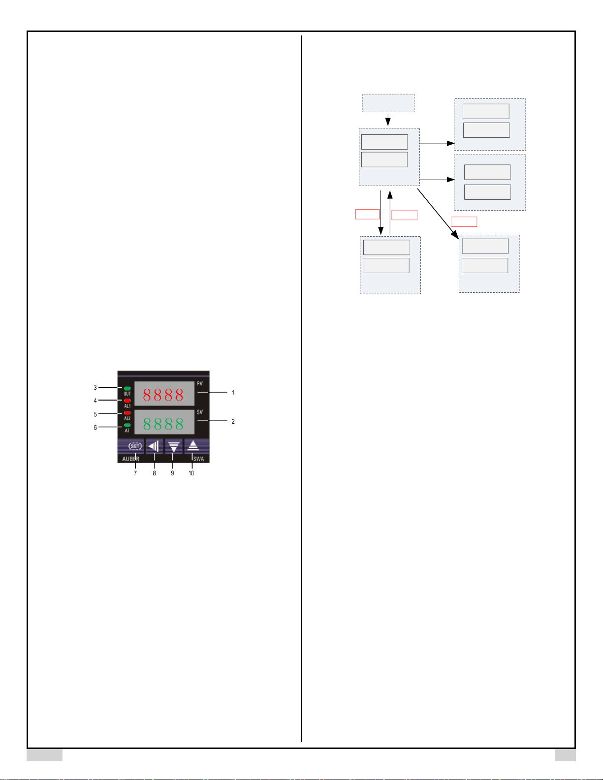
4. Front Panel and Operation
Figure 2. Front panel.
1. PV display: Indicates the sensor read out, or process value (PV).
2. SV display: Indicates the time when timer is used. If timer is deactivated, it
indicates the set temperature (SV). In manual control mode, an “H” is
displayed on the most left digit to indicate number is for percentage of
output (%).
3. Output indicator: It is synchronized with SSR output on the controller
(terminal 9 and 10). When it is on, SSR output is triggered, and your
external SSR & heater (or cooler) are powered.
4. AL1 indicator: It is synchronized with alarm 1 relay (AL1). When timer is on,
it works as the timer relay output indicator. When timer is deactivated, it
lights when Alarm 1 condition meets.
5. AL2 indicator: It is synchronized with alarm 2 relay (AL2). It lights when
Alarm 2 condition meets.
6. Auto-tune indicator: It lights up when auto-tune starts.
7. SET key: Press and hold this key for 3 seconds will enter the temperature
control parameter setting mode. When the controller is in temperature, or
timer parameter setting mode, press this key momentarily will lead the
display to the next parameter.
8. Automatic/Manual function key/Data shift key ◄: press ◄ for 3 seconds to
enter manual tuning mode. Press ◄ for 3 seconds again to exit.
9. Decrement key ▼: Decreases numeric value of the setting value. Press for
3 seconds to enter the timer setting mode.
10. Increment key ▲: Increases numeric value of the setting value. Press for 3
seconds to enter the temperature setting mode.
4.1 Display Modes
8888
20
PV
SV
◄ for 3s
Power on
Figure 3. Display modes
▲For
3s
▼For
3s
PV
SV
SV
PV
SP
100
tE1
20
◄ for 3s
PV
SV
8888
H 0
PV
SV
AL1
999.9
SET for 3s
Mode 1
Mode 2
Mode 3
Mode 4
Mode 5
Display mode 1: Normal operation display.
PV is the abbreviation for Process Value. SV is the abbreviation for Set Value.
When the power is turned on, the upper display window shows the measured
temperature value. If the timer is used, the lower window shows set timer value.
When timer starts, it shows the time as it counts up or down. If the timer is
disabled (INT = 0), the lower display shows the set temperature.
Display mode 2: Changing temperature set value (SV)
Press the ▲key for 3 seconds, and then release it. The decimal point on the
lower right corner will start to flash. Press the ▼or ▲ key to change SV until
the desired value is displayed. If the change of SV is large, press the ◄ key to
move the flashing decimal point to the desired digit that needs to be changed.
Then press the ▼or ▲key to start changing SV from that digit. The decimal
point will stop flashing after no key is pressed for 3 seconds. The changed SV
will be automatically registered without pressing the SET key.
Display mode 3: Timer parameter set up.
Press the ▼ key for 3 seconds to change the display status into timer
parameter setting mode. The upper display window shows the timer parameter
symbol to be changed, the lower display shows its value. Press the ◄, ▼or ▲
to change the setting. Then, press SET to go to next parameter. If no key is
pressed for 10 seconds, the display will return to mode 1 automatically. The
change of value will take effect without the need for pressing the SET key. See
4.14 to 4.16 for more details.
Display mode 4: Manual mode.
Press the ◄ key for 3 seconds to enter the manual mode. In this mode, the
lower display has an H on the most left. The number on the right is the
percentage of power output. Press the ▼or ▲ to adjust the power. Press the
◄ key for 3 seconds again to exit this mode. For more details, please see 4.3.
Display mode 5: Temperature control parameter setting.
Press the SET key for 3 seconds to enter the temperature control parameter
setting mode. The upper display window shows the parameter symbol to be
changed, the lower display shows its value. Press ◄, ▼or ▲ to change the
setting. Then, press SET to go to next parameter. If no key is pressed for 10
seconds, the display will return to mode 1 automatically. The change of value
 Loading...