

Auber JSL-71A Instruction Manual
AUBER INSTRUMENTS WWW.AUBERINS.COM
1
3
2
4
5
6 7 8 9
10
5
4
3
2
1
10
9
8
7
6
OUT
NC
NO
AC
90~26 0V
COM
STP
PAU
RST
Instruction Manual
JSL-71A Easy Timer with Dual Settings
Version 1.2 (Apr, 2015)
1. Overview
This JSL-71 timer can count from 0.01 second to 9999 minutes. Operating
function modes include single delay, double delay, and cycle delay. It can
count-down or count-up. The timer can be activated automatically when
powering up, by front key pad, or via remote switch. Two different time delay
settings can be programmed. User can switch the setting with a single key
press. Lock function can be activated to prevent any accidental change.
2. Specification
Timer range: 0.01 second to 9999 minutes
Timer mode: single delay, double delay, cycle delay
Timer trigger: power on, front key pad, or remote switch
Timer accuracy: <1s/day.
Power supply: 90-260V AC or DC.
Power consumption: <2W
Relay output:7A@240VAC,10@120VAC and 24VDC
Relay life: 100,000 times.
Operating temperature: 0-60 ° C.
Humidity: 0-95%RH
Panel cutout: 44.5x44.5mm
Outer dimension: 48x48x85 mm.
3. Front Panel
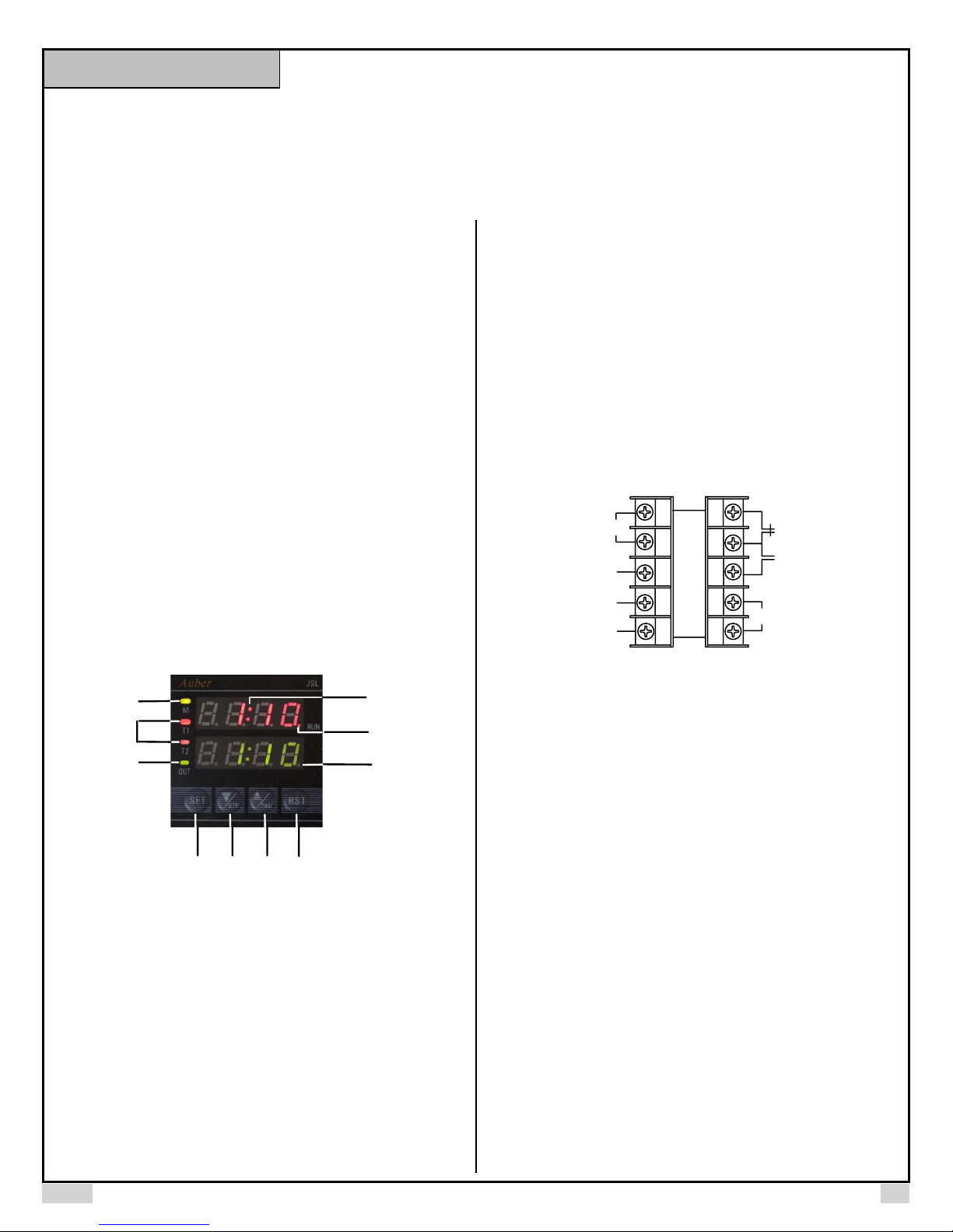
Figure1. Front panel
1. RUN indicator: (the red dot at the lower right corner).Turns on when timer
starts running. Turns off when timer stops.
2. Time unit indicator: turns on when time units are M:S or H:M. Turns off when
time unit is M or S.
3. Time range indicator: turns on when the time base is H:M (Hours: Minutes)
or M(Minutes). Turns off when the time base is M:S (Minutes : Seconds) or
S(Seconds).
4. Timer indicators: T1 for first delay time, T2 for second delay time.
5. OUT indicator: Turns on when relay is on. Turns off when relay is off.
6. SET key. When timer is not running, press it will switch between first delay
time setting (T1) and second delay time setting (T2); press and hold it for 3
second will enter the programming mode.
2015.04 P1/4
7. Down key / STP key: Lower the time setting value or stop the timer (for
special stop function please see note2 on page 5/5 for details). In the
programming mode, press it will go to the next programming value.
8. Up key / PAU key: When timer is not running, press it will increase the time
setting value. When timer is running, press and hold it will pause the timer. The
timer will continue running after this key is released. In the programming mode,
press it will go to the previous programming value.
9. RST key: Reset key. When timer is running, press it will restart the timer. If
"RUN" parameter is set to RST, press it will start the timer after powered up.
10. LED digital display. During normal operation as a timer, the top displays the
actual time; the bottom displays the set value. In programming mode, the top
displays setting parameters; the bottom displays programming value.
4. Terminal Assignment
Figure 2. Terminal assignment.
Details:
Power for the timer needs to be connected to between terminal 9 and 10. The
voltage should be in the 90 to 260V range.
Terminal 6, 7 and 8 are for relay output. Terminal 6 is Normally-closed (NC)
contact. Terminal 8 is Normally-open (NO) contact. Terminal 7 is common
contact of the terminal 6 and 8. When the relay is energized (or when the OUT
LED is on), terminal 8 connects to terminal 7, and terminal 7 disconnects
terminal 6; When the relay is NOT energized (or when the OUT LED is off),
terminal 6 connects to terminal 7, and terminal 7 disconnects terminal 8. The
relay is a “dry switch” that does not provide power by itself. Please see the
wiring example below.
Terminal 5 is the reset terminal that has the same function as the RST key in
the front panel. Terminal 4 is the pause/mute terminal that function the same
as the “^/PAU” key in the front panel. Terminal 3 is the stop terminal that
function the same as the “V/STP” key in the front panel. Terminal 1 and 2 are
the common contacts of the terminal 3/4/5. There are two ways to operate
terminal 3, 4 and 5.
1) Connecting a normally open (NO) momentary push button switch between
the terminal (3, 4 or 5) to the COM (1 or 2). Please note, the function starts
when you release (or open) the button of the switch, not when you press down
the switch.
AUBER INSTRUMENTS WWW.AUBERINS.COM
trnG
s
0000
0000
trnG
S
Process Value
Set Value
SET
OUT
OFDL
TDIR
dn
OUT
OFDL
tdir
dn
SET
FUNC
SDL
RUN
RST
Func
SdL
RUN
rSt
LU.SP
ONON
LU.SP
ON.ON
SET
SET
SET
3s
SET
2) Connecting a DC logic signal (TTL or CMOS or voltage in the range from 3
to 30 VDC) between the terminal (3, 4 or 5) to the COM (1 or 2). Please note,
the function is rising-edge triggered. The logic signal should normally be at high
level. The function starts when the signal goes from low to high. If you have an
inverted logic signal, you need to connect a NPN transistor between terminal
and COM; add 10Kohm resistor to the gate for signal input.
5. How to Set the Timer and Relay Delay Time T1/T2
When timer is not running, press “SET” key to shift between relay delay time
T1 and T2. Simply press up/ down key will increase/decrease the set value of
each delay time. (hold up/down key to speed up changing).
For how to program the relay delay time in different relay output mode, please
see the definition of Func in next section.
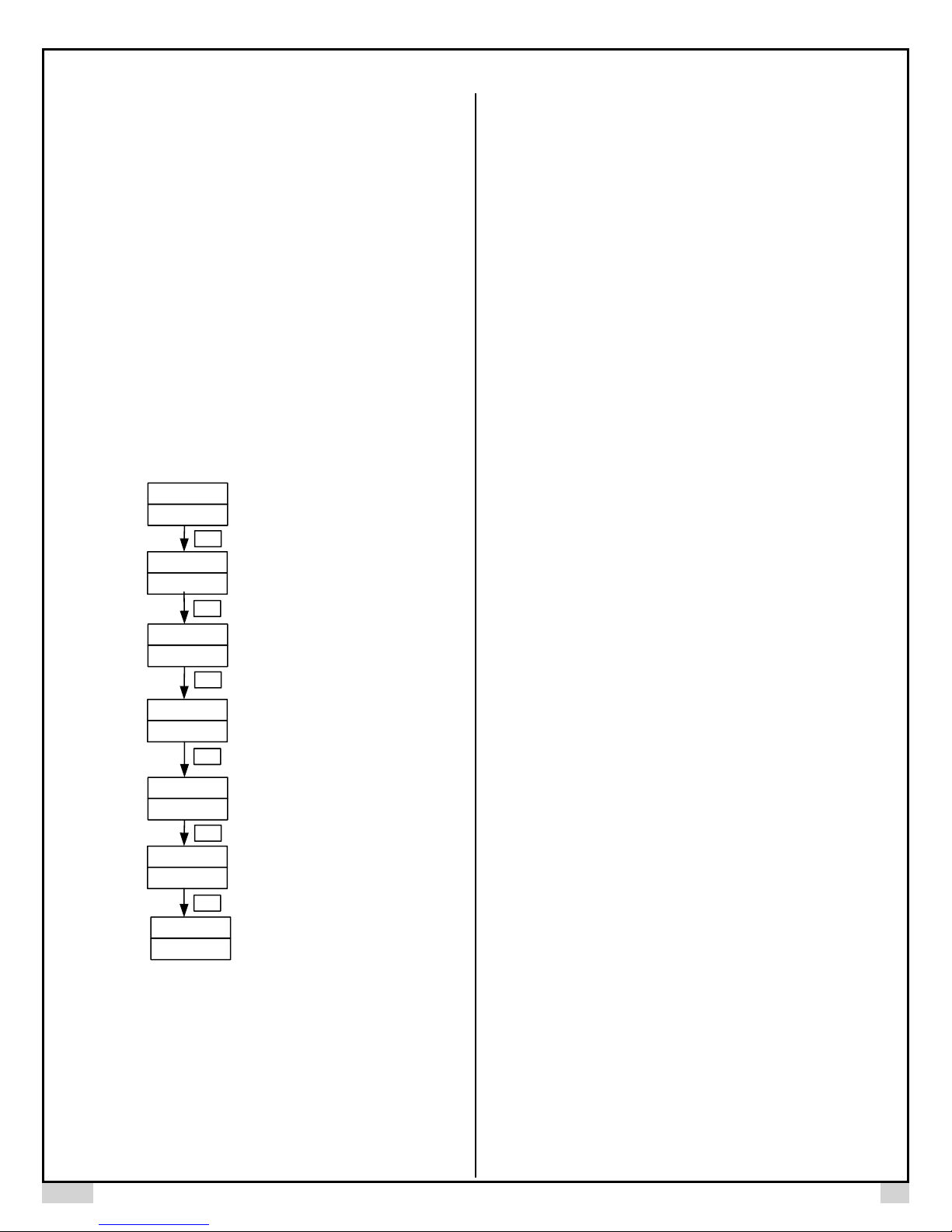
6. Programming
Press SET key for 3 seconds to enter programming mode. For each parameter
setting, use up/down key to select different programming values. Press SET
key to confirm and move on to next parameter. See figure 3 next page for the
procedure. For the definition of each programming value, see following section.
2015.04 P2/4
Definition of Programming Values:
trnG: Timer range
S:0.01s~99.99s;
M:S: 1s~99m59s;
M:1m~9999m;
H:M: 1m~99h59m
Figure 3. Flow chart of programming
tdir: Timing direction
up: Counting up
dn: Counting down
OUT: Relay output mode
OFDL (off delay): Relay will be on at the start of timer and off when time reach
the set point.
ONDL (on delay): Relay will stay off at the start of timer and on when time
reach the set
RUN: Timer starting run mode
PU (power up):Timer starts when powered up
rSt (reset):Timer starts when reset button is pressed and released
Func: Timer operating function mode
sdL (single delay): Relay turns on at the beginning of relay delay time
T1/T2(OFDL); Relay turns on at the end of relay delay time T1/T2(ONDL). It
will not change until the timer is reset or repowered again.
In Single Delay ON mode, a special parameter for stop function, STOP, will
show up in the parameter menu. For details please refer to note 2 at the end of
the manual, page 5/5.
Dint (delayed interval): Relay turns on at the end of T1 time delay then off at
the end of T2 time delay (OFDL); Relay turns off at the end of T1 time delay
then on at the end of T2 time delay (ONDL). There is no repeat.
CYCL(cycle): Repeat relay on and off in cycle. Relay turns on at the end of T1
time delay then off at the end of T2 time delay (OFDL); Relay turns off at the
end of T1 time delay then on at the end of T2 time delay (ONDL). It will repeat
this cycle until power is off.
LU.SP: Key locker for the two key pads in the middle.
This parameter determines if the two keys in the middle will be locked for timer
value setting or stop/pause function. For some applications that repeat the
same time setting, user may want the lower and up key to be locked to prevent
any accidental change. For other applications, user may want the Stop and
Pause function to be deactivated to prevent stopping the timer by accident.
LU.SP represents Lower, Up, Stop and Pause function. OF means the function
is turned off and ON means the function is turned on.
LU.SP set to OF.ON means the lower and up keys are deactivated (turned off),
but Stop and Pause keys are still functional (turned on)
ON.OF means lower and up keys are functional, but Stop and Pause functions
are turned off.
OF.OF means lower and up keys, Stop and Pause functions are all locked up.
ON.ON means lower and up keys, Stop and Pause functions are all functional.
Note 1: When the Stop and Pause are locked from the front keys, the Stop and
Pause function can still be executed from the back terminals.
 Loading...