

Auber AT100KLN User Manual
Instruction Manual for AT100KLN
Version 1.3
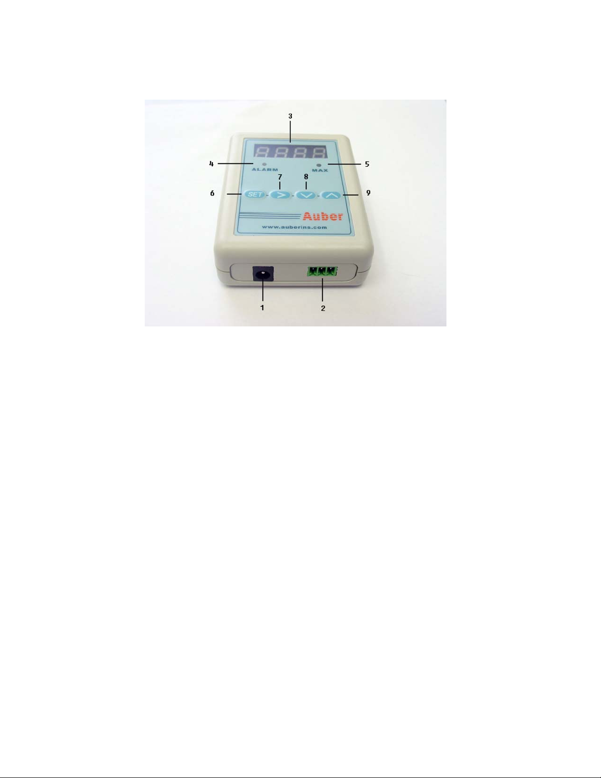
Figure 1. Thermometer identification
Thermometer identification
1. Connect to 12VDC power adapter
2. Connect to temperature sensor
3. Display window
4. Alarm indicator : blink when alarm is triggered
5. Peak value indicator : solid on when peak temperature is displayed / blink when it shows the
time when peak temperature is reached
6. Set key: enter code / confirm input value
7. Shift key: shift digit / silence alarm buzzer
8. Down key: change digit value / move to former parameter / shift to peak temperature and the
time when peak temperature is reached/ reset peak values
9. Up key : change digit value / move to next parameter / shift brightness
Keys for measurement operation
Figure 2 shows the function keys during the temperature measurement operation (The function
keys for configuring the meter are discussed in the later section).
1

Figure 2 Function keys during temperature measurement operation
Notes:
1. When the temperature reaches the alarm temperature, the alarm indicator will flash and meter
will start beeping. Press shif t key once can tem poraril y silence the alarm. Alarm will be retri ggered if
the alarm set temperature is reached again. To permanently deactivate the alarm, set AH=AL.
2. Press down key once to show peak temperature; press again to show the time when peak
temperature is reached (count from the start of temperature rising, display unit: seconds). If the
temperature continued rising, a new peak temperature and its time will be recorded. They will be
memorized even after power is restarted.
After power is restarted, previous recorded peak and its time will stay in the memory unless: 1)
there is a new peak temperature higher than the previous peak, 2) or the memory has been reset.
Hold the down key for 2 seconds will reset the peak temperature and its time to 0. The new time is
counted from restarting the power or from reset (display unit: seconds).
3. Press up key once to show the dimmed display reading. Press again to show the normal
brightness display reading. The brightness of the dimme d di spl ay is determined by the parameter
“brit” described in the later section of the manual.
Connecting the meter and probe
Thermocouple connection. The connection between thermocouple and extension wire is shown in
Fig 3. Both the thermocouple and the cable are polarized. The negative of the thermocouple
has a red ink mark at the end. The nega tive of th e extensio n cable has a re d insul ati on ja cket. If t he
thermocouple polarity is reversed, the reading will decrease when temperature increases. If the
cable is reversed, you will get at least 40 F error in reading. The negative of the thermocouple wire
and the negative of the extension cable should be connected to the same brass terminal block on
the oval shaped terminal plate as shown in Fig 3.
2
 Loading...