

Page 1

SC1000 Fiber Laser Cutting
CNC System User’s Manual
WUHAN AU3TECH TRADING CO., LTD
Version: V1.00
2017/3/27
Page 2
Copyright © WUHAN AU3TECH TRADING CO., LTD
2
SC1000 Fiber Laser Cutting CNC System User’s Manual Version: V1.00
2017 年 3月 27 日
Preface
Introduction
This archive mainly describes about the interface, functions and operations of the fiber laser cutting
CNC system software (We call it: SC1000). And if you want to know more about installation and
debugging, please reference to Fiber Laser Cutting CNC System Quick Setup. Before you use it and
its relevant equipment, please read it carefully which can help you use it more conveniently. And since
our product are keeping updating, so this manual cannot fully match in all aspects with the product, hope
you can understand.
Readers
This manual mainly for those people below:
Installation / debugging engineer
Maintenance engineer
Operator
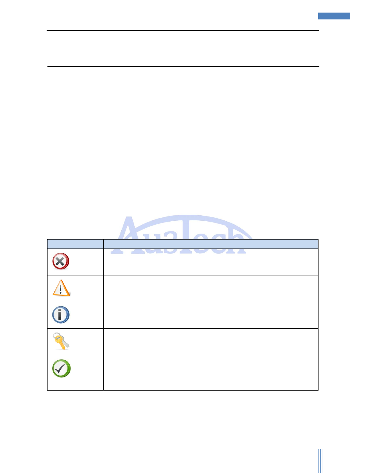
The meaning of symbols
Symbol
Meaning
Forbidden
It means high potential risk, if can’t avoid, which can result in seriously damaging
to equipment or even hurting people.
Alarm
It means medium or low potential risk, if can’t avoid, which can result in slightly
or moderately damaging to equipment or hurting people.
Attention
It means potential risk, if ignore this manual, which can result in damaging the
equipment, losing all the data or some unpredictable results.
Tips
It means can help you solve some problem or save your time.
Explanation
It means additional information, which emphasizes and supplements the main
part of manual.
Modification record
Modification record accumulates each updated descriptions of this archive. The newest updated
archive includes all the updated contents of the old version.
Page 3

Copyright © WUHAN AU3TECH TRADING CO., LTD
3
SC1000 Fiber Laser Cutting CNC System User’s Manual Version: V1.00
2017 年 3月 27 日
Version V1.00(2017-5)
Page 4

Copyright © WUHAN AU3TECH TRADING CO., LTD
4
SC1000 Fiber Laser Cutting CNC System User’s Manual Version: V1.00
2017 年 3月 27 日
Content
Preface ........................................................................................................................................... 2
Introduction ................................................................................................................................. 2
Readers ...................................................................................................................................... 2
The meaning of symbols ............................................................................................................. 2
Modification record ...................................................................................................................... 2
1 Introductions ................................................................................................................................ 6
1.1 Introduction of products ......................................................................................................... 6
1.2 UI and descriptions ................................................................................................................ 6
2 0perations .................................................................................................................................... 9
2.1 Quick actions ......................................................................................................................... 9
2.1.1 Operation flowchart ......................................................................................................... 9
2.1.2 Graphic importing/drawing .............................................................................................. 9
2.1.3 Graphic processing ......................................................................................................... 9
2.1.4 Cutting tracts ................................................................................................................. 11
2.1.5 Cutting process setting .................................................................................................. 12
2.1.6 Checking before cutting ................................................................................................ 13
2.1.7 Cutting .......................................................................................................................... 14
3 Functions ................................................................................................................................... 17
3.1 Tittle bar .............................................................................................................................. 17
3.2 Tool option........................................................................................................................... 17
3.2.1 Start .............................................................................................................................. 17
3.2.2 Draw ............................................................................................................................. 19
3.2.3 System analysis ............................................................................................................ 29
3.2.4 Advanced ...................................................................................................................... 32
3.3 View section ........................................................................................................................ 39
3.4 Running control option ......................................................................................................... 40
3.4.1 Running control ............................................................................................................. 40
3.4.2 Running parameters ...................................................................................................... 42
3.5 Message bar ........................................................................................................................ 43
Page 5

Copyright © WUHAN AU3TECH TRADING CO., LTD
5
SC1000 Fiber Laser Cutting CNC System User’s Manual Version: V1.00
2017 年 3月 27 日
3.6 Layer parameters option ...................................................................................................... 44
3.7 Status bar ............................................................................................................................ 47
4 Warning and exceptions handling .............................................................................................. 48
4.1 System alarm and descriptions ................................................................ ............................ 48
4.2 Normal exceptions and handling .......................................................................................... 50
4.2.1 System communication exceptions ............................................................................... 50
4.2.2 Reposition exceptions ................................ ................................................................... 52
4.2.3 Pulse equivalent setting ................................................................................................ 53
4.2.4 Fly-cutting debugging .................................................................................................... 53
Page 6

Copyright © WUHAN AU3TECH TRADING CO., LTD
6
SC1000 Fiber Laser Cutting CNC System User’s Manual Version: V1.00
2017 年 3月 27 日
1 Introductions
1.1 Introduction of products
SC1000 is a flat fiber laser cutting CNC system software which includes graphic drawing and editing,
cutting process dealing, cutting process controlling, system monitoring, components monitoring and
debugging, and so on.
Features:
1) Operations are simple but functions are powerful.
Developed based on RIBBON framework, software is not only beautiful but also easy to operate.
UI design is more humanize, which is easier to use without training.
With powerful CAM functions based on AUTOCAD design, support graphic import, graphic drawing,
graphic editing, and graphic transformation, graphic optimized and so on.
Intelligent capturing, which makes drawing more convenient and accurate.
Unique properties option design, which helps user to design the cutting graphic more easily.
Support various sort methods, auto sort can recognize the film inside or outside the graphic to make
sure the path planning optimized.
Powerful lead line function, support various ways to lead line, auto added suitable lead line based
on graphic nested relations. Support check/revise interfered lead line by one click.
2) Complete cutting process, debugging easily
Support all kinds of cutting process: Section drill, gradual drill, 3 stages drill, cutting with film, fix
height cutting, and predrill and so on.
Support laser’s power/frequency adjusted with speed, to decrease or avoid the problem of firing
corners when cutting carbon steel.
Support multilayer cutting or marking, and other sorts of processing ways.
Support micro-joint, gap, over-cutting, bridge, kerf-compensation and so on.
Powerful material database, which can save all sorts of material cutting process.
Support complex functions: Edge seeking, fly-cutting and so on.
Support breakdown position tracking/forward/backward and so on.
3) Rea-time alarm, stable and reliable.
Support running error measurement, it can check the error between running orbit and graphic error.
Real-time alarming the status of capacitive height controller, laser, gas and other equipment, make
sure the security during cutting.
More than 50 different kinds of alarms, to secure the equipment in whole aspect, avoid user’s wrong
operation.
1.2 UI and descriptions
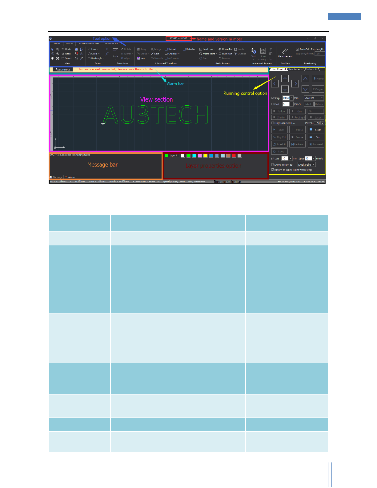
Graphic 1-1 UI
Page 7
Copyright © WUHAN AU3TECH TRADING CO., LTD
7
SC1000 Fiber Laser Cutting CNC System User’s Manual Version: V1.00
2017 年 3月 27 日
UI design is very clear, from up to down: title option, tool option, alarm option, view option, running
control option, message bar, graphic parameters option, and status bar. The functions of each section
shows as below:
Name
Functions
Remark
Tittle bar
Display software’s name and version number.
Tool option
Mainly collects the tools needed for software
operation, it has four submenu:
START/DRAW/SYSTEM
ANALYSIS/ADVANCED. User can do graphic
drawing, graphic editing, graphic
transformation, adding lead line, monitoring
running status, configuration machine tool.
Alarm bar
Display the current system alarm.
Alarm will be displayed in
pop-up window, and once
the alarm is cleared, the
pop-up window will be
gone.
View section
Graphic drawing/displaying section, machine
tool’s width displaying section. (机床幅面显示
区).
Running control
option
Run all kinds of cutting actions through
software.
Message bar
Display the current running status in scrolling.
Layer properties
Set up layer properties such as layer process,
Page 8

Copyright © WUHAN AU3TECH TRADING CO., LTD
8
SC1000 Fiber Laser Cutting CNC System User’s Manual Version: V1.00
2017 年 3月 27 日
option
graphic transformation and so on.
Running status
Display the running status, running location,
cutting speed and so on.
Page 9
Copyright © WUHAN AU3TECH TRADING CO., LTD
9
SC1000 Fiber Laser Cutting CNC System User’s Manual Version: V1.00
2017 年 3月 27 日
2 0perations
2.1 Quick actions
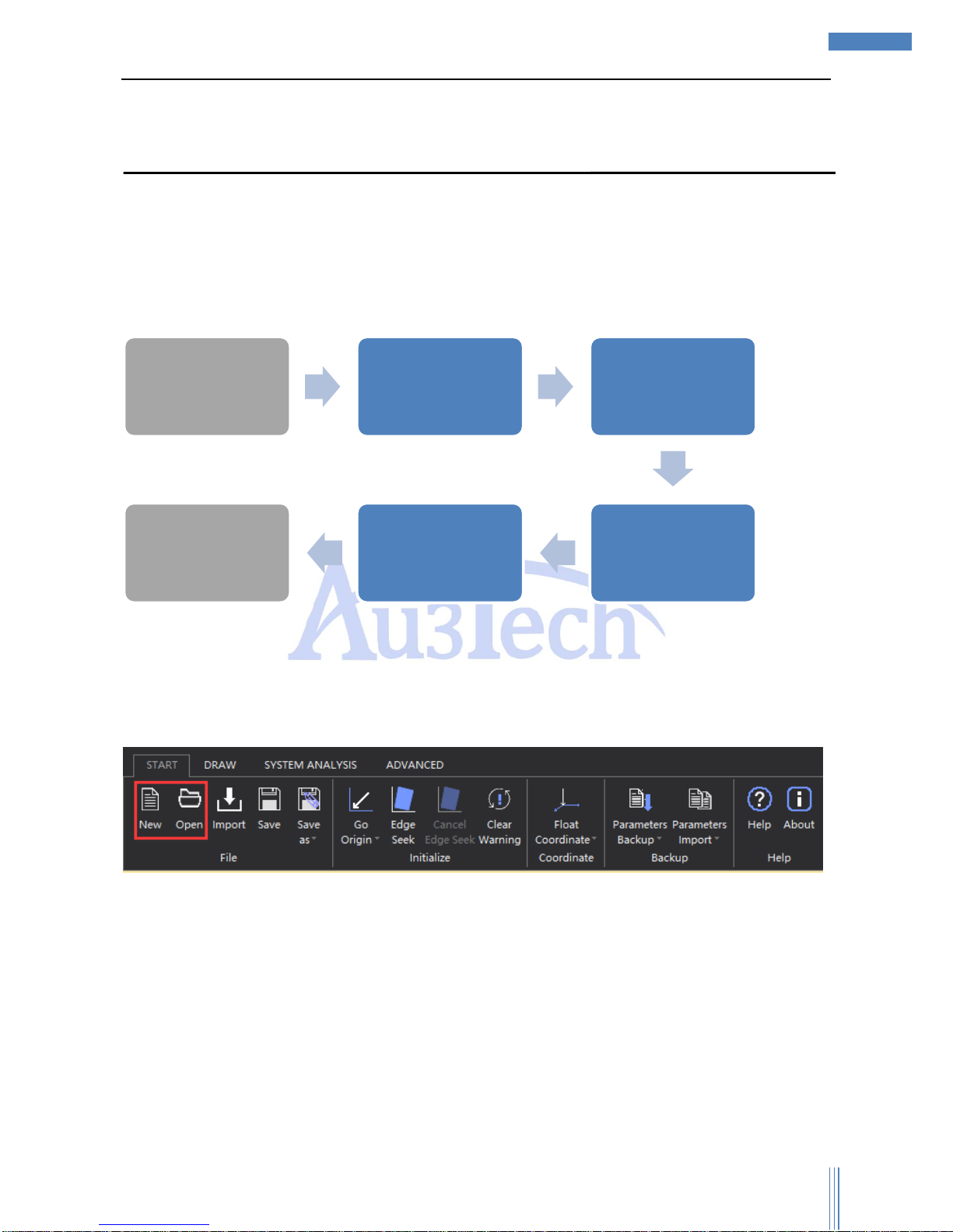
2.1.1 Operation flowchart
2.1.2 Graphic importing/drawing
After start the software, user can import the file according to his needs or he can draw it by the
drawing tool in the software.
Choose “START”—>“Open”, import the cutting file.
Choose “New” can build a new view section, user can draw any parts he need when cutting.
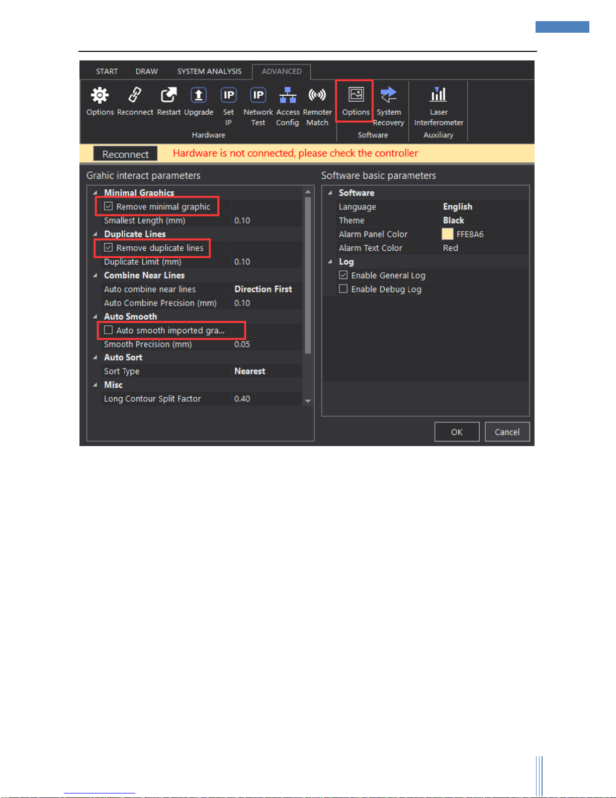
2.1.3 Graphic processing
Before importing the cutting file, user can set up all the conditions he needs, including whether to
auto remove minimal graphics, or whether to auto remove duplicate lines and so on.
Choose “ADVANCED”—>“Options”, select the options as below:
Graphic
import/drawing
Graphic dealing Path planning
Cutting process
setting
Checking before
cutting
Cutting
Page 10
Copyright © WUHAN AU3TECH TRADING CO., LTD
10
SC1000 Fiber Laser Cutting CNC System User’s Manual Version: V1.00
2017 年 3月 27 日
After importing/ newly building the file, user can revise the file if they need.
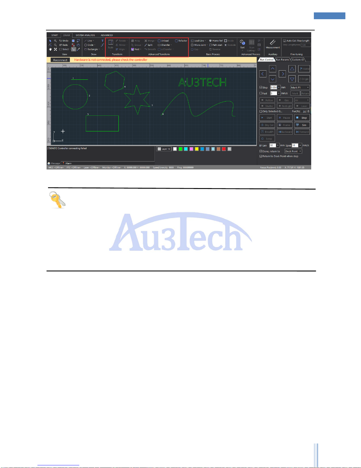
1、Choose in tool option “DRAW”,select suitable tool to revise the graphic: Zoom in/out in proportion,
rotate, mirror, align, array, group, nest, merge, split, smooth, unload, chamfer, chamfer R,
refactor, fill circle.
2、Or use graphic transformation to adjust the graphics.
Page 11
Copyright © WUHAN AU3TECH TRADING CO., LTD
11
SC1000 Fiber Laser Cutting CNC System User’s Manual Version: V1.00
2017 年 3月 27 日
Tips
User can quickly revise the selected graphics in its coordinate, size, alignment point, and cutting
sort and so on in property option. It’s also very convenient for user to adjust the graphics using these
tools.
Layer parameters can be used to revise the parameters of the selected graphic: uncut, short no-lift,
unfollow, direct, section drill, gradual drill, fix height drill, with film, keep gas on, and so on.
User can set chamfer R for rectangle.
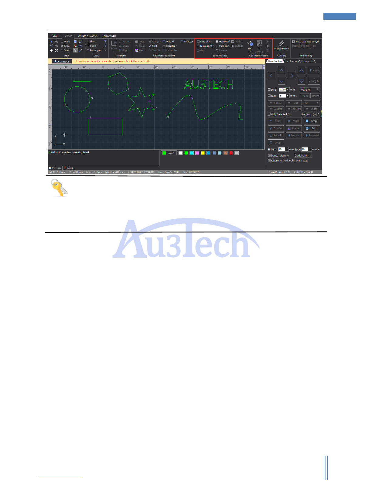
2.1.4 Cutting tracts
After adjusting the cutting graphic, then comes path planning, including the lead line setting,
micro-joint, gap, home ref, path start, reverse, inside, outside.
Page 12
Copyright © WUHAN AU3TECH TRADING CO., LTD
12
SC1000 Fiber Laser Cutting CNC System User’s Manual Version: V1.00
2017 年 3月 27 日
Tips
Support auto/manual adding lead line, and checking the interfered lead line.
Support various sort methods, please select by clicking “Sort”. Auto-recognize the film
inside/outside the graphic when sorting.
2.1.5 Cutting process setting
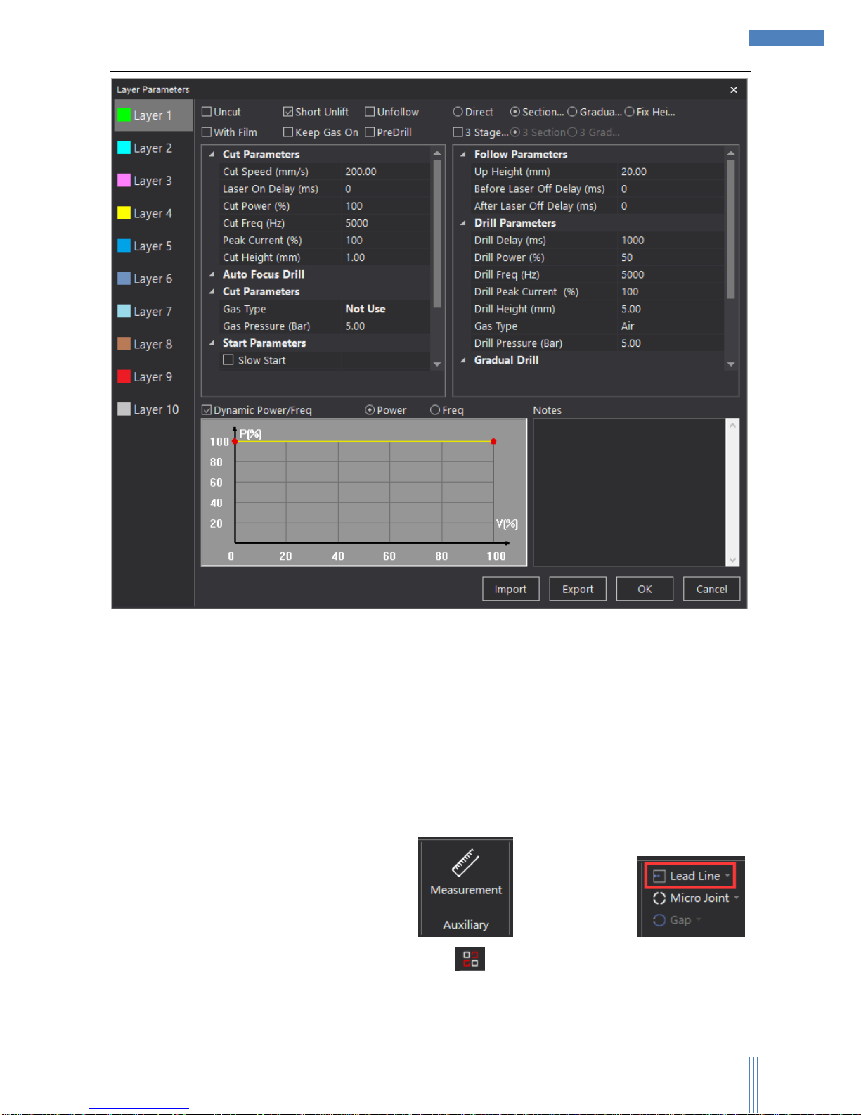
After checking the path planning, please set up the cutting process. SC1000 supports multi-layers: 1
background layer, 10 cutting layers. And the parameters of each layer can be set up separately
according to user’s needs. Click the “Layer X” in the graphic properties to set up the layer parameters,
as below:
Page 13
Copyright © WUHAN AU3TECH TRADING CO., LTD
13
SC1000 Fiber Laser Cutting CNC System User’s Manual Version: V1.00
2017 年 3月 27 日
User can set up different parameters to achieve the best situation of cutting: cutting ways, cutting
speed, cutting power, gas type/pressure, up height and so on.
2.1.6 Checking before cutting
Before you really start cutting, please check the cutting graphics and path planning to make sure
everything has been settled properly.
1) Please check the cutting graphic in these aspects: Size, lead line, sort, unclosed curve, minimal
graphic, similar graphic.
2) SC1000 can measure the size of the graphic and check lead line ,
it can also auto-remove the interfered lead line. It shows the unclosed graphic. You can
choose unclosed curve/minimal graphic/similar graphic in “Select”.
3) Please check the path planning in these aspects: Cutting frame, running tracks and so on by
Page 14
Copyright © WUHAN AU3TECH TRADING CO., LTD
14
SC1000 Fiber Laser Cutting CNC System User’s Manual Version: V1.00
2017 年 3月 27 日
setting parameters in running control option.
4) Click “Edge seek”, SC1000 will order the machine to run along the graphic frame, so user can
check whether if the workpiece is inside the frame or not so that user can adjust the place of the
graphic/workpiece.
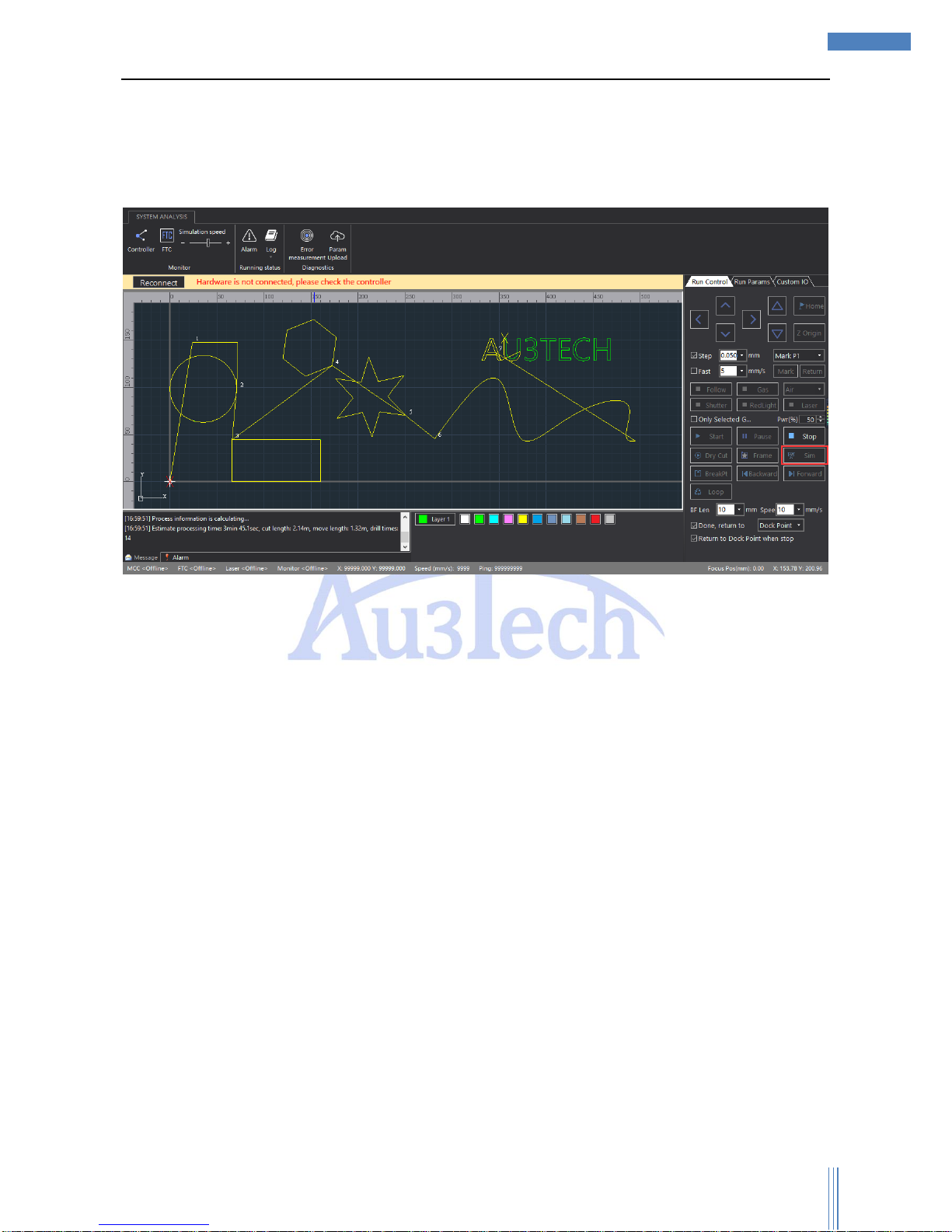
5) Click “Sim”, SC1000 will auto-simulate the cutting track, and the simulation speed can be adjusted.
2.1.7 Cutting
The running control must be done on the real machine. So the motion control card must
communicate with SC1000 normally, or the relevant buttons will turn gray and can’t be selected.
Page 15
Copyright © WUHAN AU3TECH TRADING CO., LTD
15
SC1000 Fiber Laser Cutting CNC System User’s Manual Version: V1.00
2017 年 3月 27 日
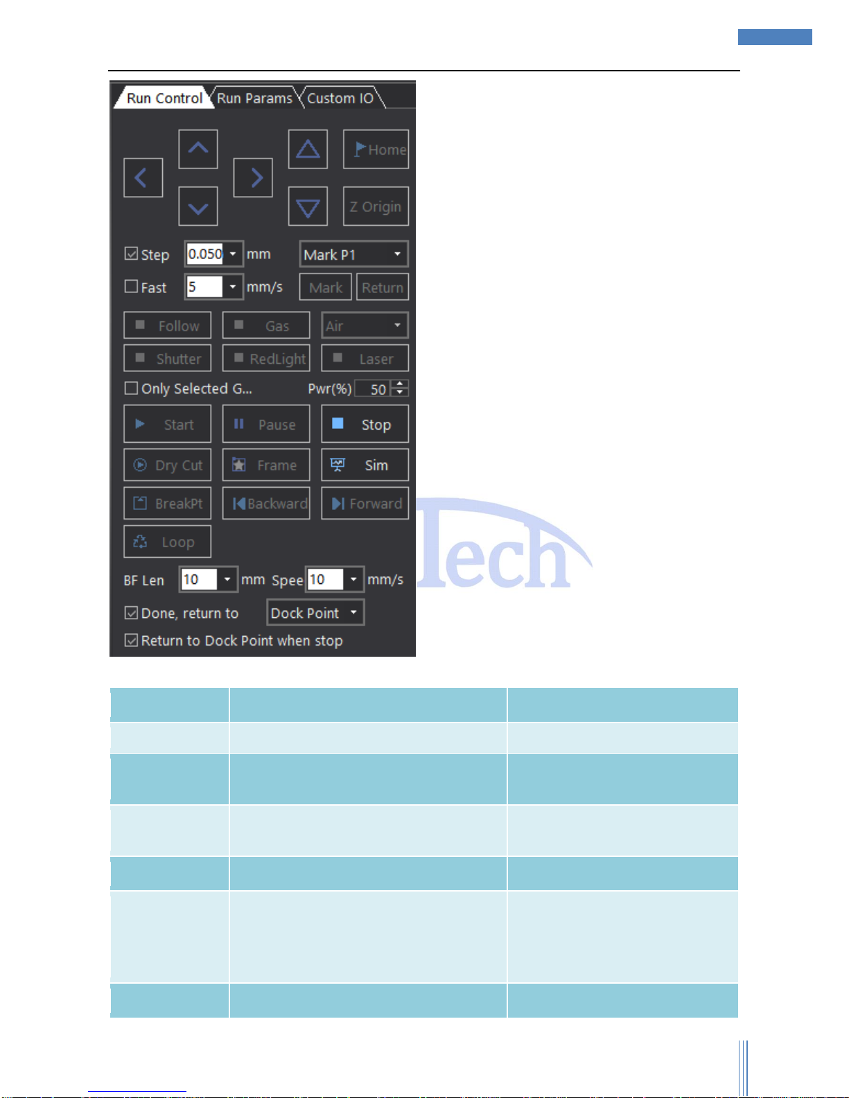
The meaning of each button shows as below:
Name
Functions
Remark
Start
Start cutting.
Continue after
pause
User can continue the cutting process after
pause cutting.
After start
Pause
Pause cutting, SC1000 will reserve the
current cutting information.
Stop
Stop cutting.
Dry Cut
Cutting without laser.
If user wants Z axis to follow when
dry cut, please select “Enable
Follow When Dry Cut” in “Run
Parameters”.
Frame
Cutting the frame of the selected graphic
Make sure the cutting graphic is
Page 16

Copyright © WUHAN AU3TECH TRADING CO., LTD
16
SC1000 Fiber Laser Cutting CNC System User’s Manual Version: V1.00
2017 年 3月 27 日
without laser.
inside the workpiece.
Sim
Simulate the cutting process without laser.
BreakPt
SC1000 will auto locate the breakpoint
after pause/stop.
Backward
SC1000 will go backward some distance
after pause/locate the breakpoint.
User can set up the backward
speed/distance.
Forward
SC1000 will go forward some distance
after pause/locate the breakpoint.
User can set up the forward
speed/distance.
Loop
Mainly to cut the same graphic repeatedly.
User can set up the time and
spacing distance
Page 17
Copyright © WUHAN AU3TECH TRADING CO., LTD
17
SC1000 Fiber Laser Cutting CNC System User’s Manual Version: V1.00
2017 年 3月 27 日
3 Functions
3.1 Tittle bar
Tittle bar shows SC1000’s logo and the version. User can check whether the version is the newest
one, and if not, please download on our website: www.au3tech.com
3.2 Tool option
3.2.1 Start
3.2.1.1 File
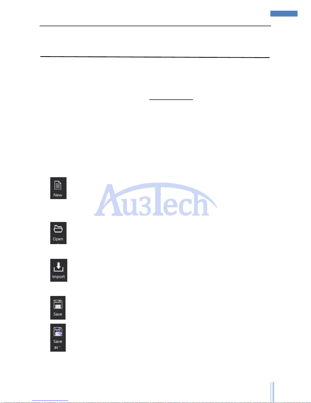
There are five functions in file part: “New”, “Open”, “Import”, “Save”, “Save as”.
1) :Build a new view section, the former graphic will be covered and SC1000 will ask the user
whether if to save the old graphic or not to avoid false operation and lose all the graphics in the old
view section.
2) :Open a new graphic, and the former graphic on the view section will be covered by the
graphic user just opened.
3) :Import a graphic user already has, and the former graphics on the view section will be
covered by the graphics user just opened.
4) : Save the graphics on the view section.
5) : Save the graphics on the view section in “.chf” or “.dxf” / at anywhere you want on the
computer. User can also choose to export to sheets.
Page 18
Copyright © WUHAN AU3TECH TRADING CO., LTD
18
SC1000 Fiber Laser Cutting CNC System User’s Manual Version: V1.00
2017 年 3月 27 日
Tips
Click the dropdown menu of “Open” to check the file list recently opened, and user can easily find
the file he opened before.
3.2.1.2 Initialization
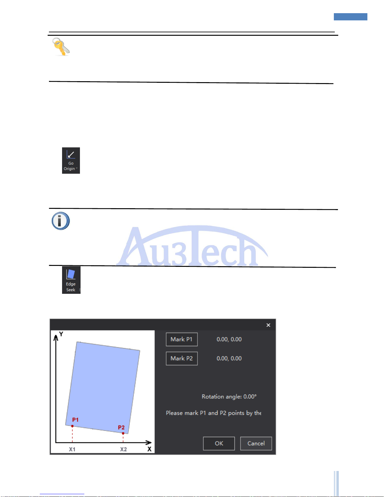
The initialization part collects all the functions user will be use at the beginning when all the
equipment power on: “Go origin”, “Edge seek”, “Cancel edge seek”, “Clear warning”.
1) :After Z axis go back to origin, X axis and Y axis go back to origin of machine at the same
time (default). Or user can choose “Only Z follower” (only Z axis go origin), “Only X” (only X
axis go origin), “Only Y” (only Y axis go origin).
Attention
Before axis go origin, please make sure the parameters of direction/type/speed and other
parameters have already been set. Make sure “Go origin” button works properly and no obstacles
on the workpiece sheet. Or it can possibly result in damaging to machine or even hurting people.
2) :According to the real place of the workpiece sheet to revise the coordinate of SC1000, so
that user can make sure the cutting graphics are inside the workpiece sheet without moving the
sheet. Click the “Edge seek” button, UI shows as below:
Page 19
Copyright © WUHAN AU3TECH TRADING CO., LTD
19
SC1000 Fiber Laser Cutting CNC System User’s Manual Version: V1.00
2017 年 3月 27 日
User can use the red light of laser from cutting head to seek one point along the edge of X axis and
mark “P1”. Then move to another point along the edge of X axis and mark “P2”. After SC1000
auto-calculate the rotation angle, it’ll revise the coordinate accordingly. Click the “OK” button, then “Edge
seek” is over successfully.
“Cancel edge seek”: after finish edge seek, the coordinate will rotate accordingly. And if you want
SC1000 go back to the original coordinate, just click “Cancel edge seek”.
3) :System alarm has two different kinds of alarms: auto-clear warning and manual clear
warning. For example, “Servo alarm” is manual clear warning, after clear all the problems of servo
equipment, user can only clear the warning of SC1000 by clicking “Clear warning” button so that to
make sure the safety of user and the equipment.
3.2.1.3 Help
1) :Click “Help”, user can check SC1000 user’s manual.
2) :Click “About” to check the information of version.
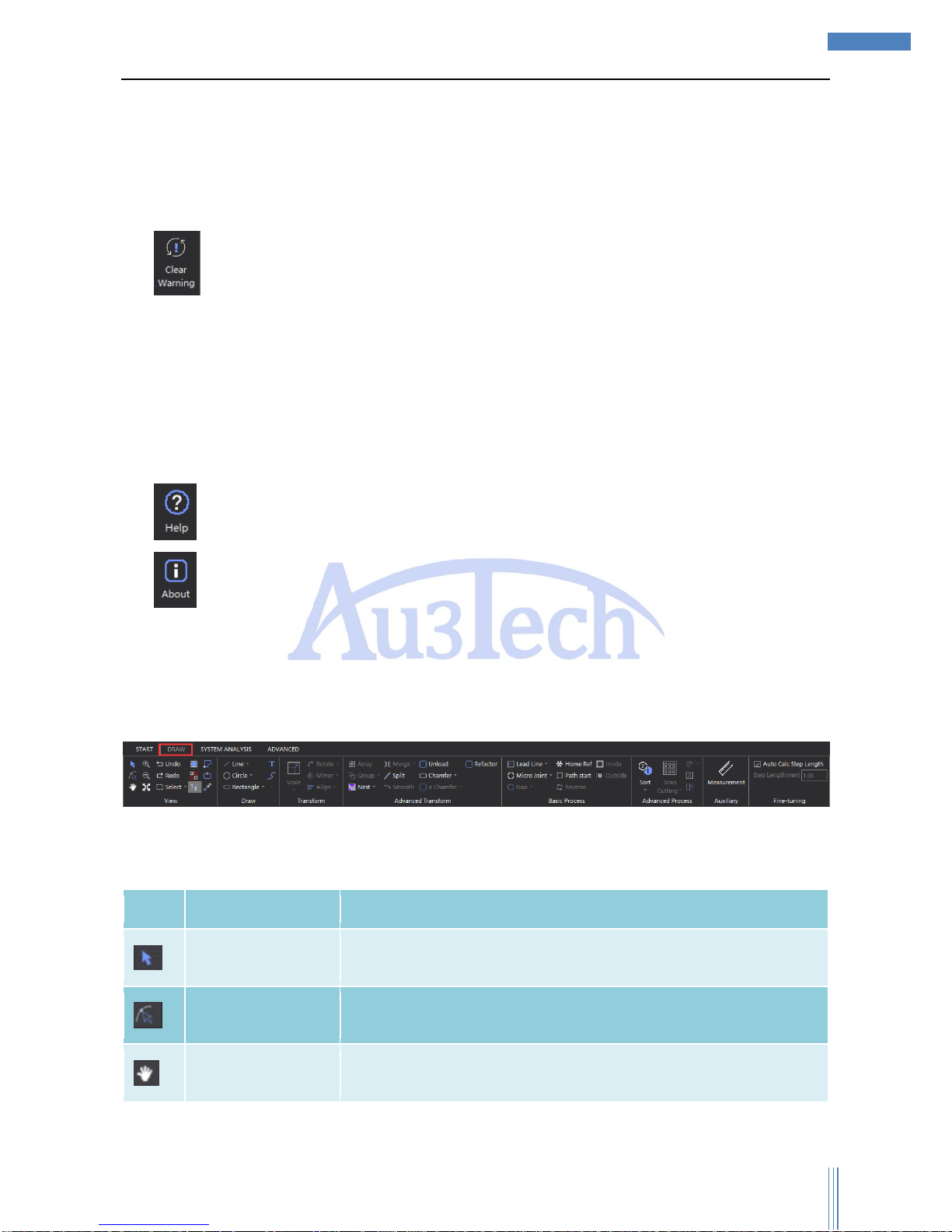
3.2.2 Draw
“View” collects all the functions related to graphic editing/path planning, user can easily design the
cutting graphics and process he needs.
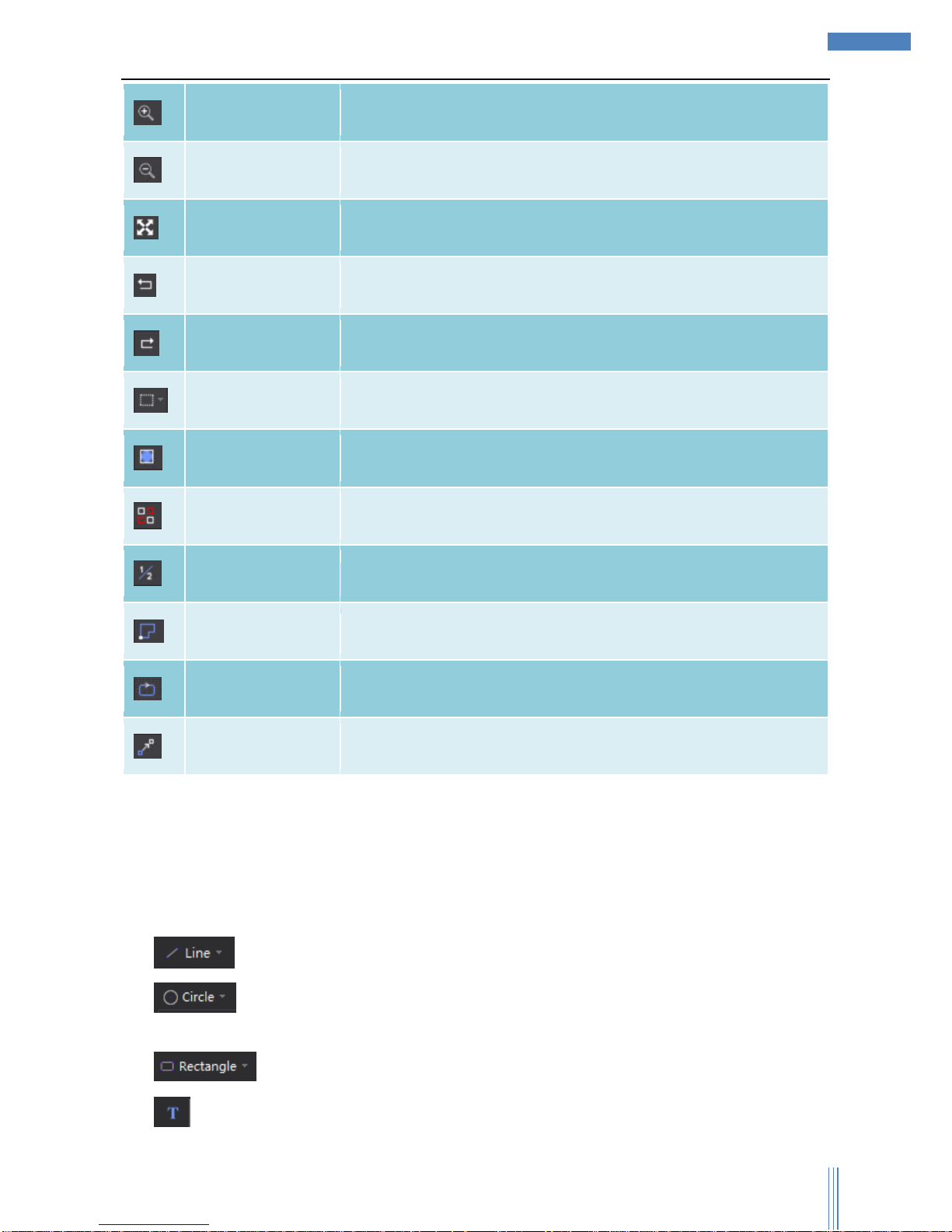
3.2.2.1 View
Icon
Name
Function
Contour Select
User can select one/all graphics.
Vertex Edit
User can edit the vertex of the selected graphic.
View Move
User can move the view section by pressing the Mouse left.
Page 20
Copyright © WUHAN AU3TECH TRADING CO., LTD
20
SC1000 Fiber Laser Cutting CNC System User’s Manual Version: V1.00
2017 年 3月 27 日
Zoom in
User can zoom in the graphic in the view section.
Zoom out
User can zoom out the graphic in the view section.
Zoom Reset
User can restore the size of the graphic in view section to the original
size.
Revoke
Revoke the latest operation.
Redo
Redo the latest operation.
Select
User can choose “Select All”, “Invert Selection”, “Select unclosed
curve”, “Select graphics smaller than”, “Select similar curve”.
Show box for
graphics
User can click here to show the box of graphic on view section.
Show unclosed
curve as red
User can click here to show unclosed curve as red.
Show index
User can click here to show index.
Show path start
User can click here to show path start.
Show path direction
User can click here to show path direction.
Show move path
User can click here to show move path.
3.2.2.2 Draw
“Draw” part collects all the functions related to drawing, which based on AUTOCAD, user can
easily design any graphic he want.
1) :Draw line. Click Mouse Right to finish the current drawing by selecting “End Draw”.
2) :Draw circle/circular arc/ellipse. User can choose “Point Circle”, “Point Arc”, “Scan
Arc”, and “Ellipse” through dropdown menu.
3) :Draw rectangle/rounded rectangle/polygon/star through dropdown menu.
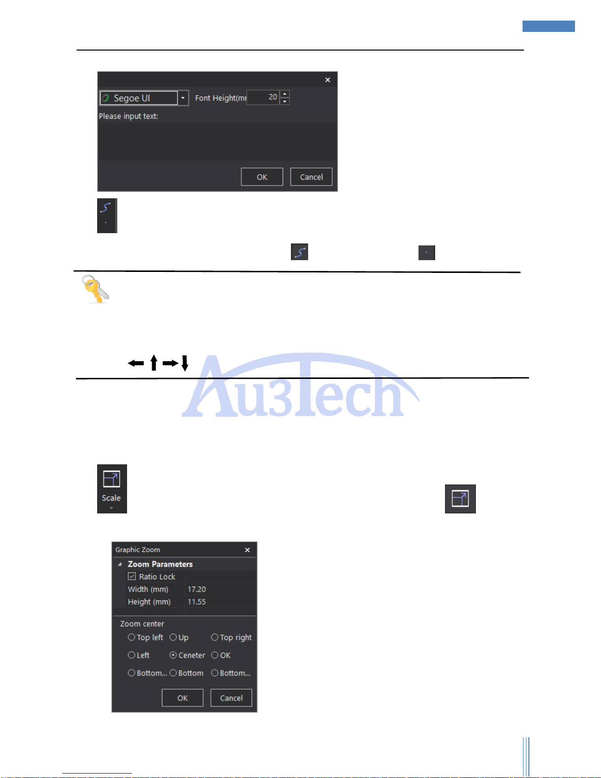
4) :Input text. Support various ways of typing text, and user can set up the parameters of text,
Page 21
Copyright © WUHAN AU3TECH TRADING CO., LTD
21
SC1000 Fiber Laser Cutting CNC System User’s Manual Version: V1.00
2017 年 3月 27 日
such as typeface, font height and so on.
5) :User can draw curve in “Polyline” and select closed graphics through Mouse Right.
6) User can continuously draw Bezier Curve in “ ”. User can draw point in “ ”.
Tips
User can draw through shortcut-menu by Mouse Right.
SC1000 can auto-capture the key point, user can make full use of this function during draw.
Click “Ctrl+C” and move the mouse at the same time to copy the selected graphic.
Click “ ” on the keyboard to adjust the place of selected graphic.
3.2.2.3 Graphic transformation
User can adjust the size/angle and so on in “Transform” part.
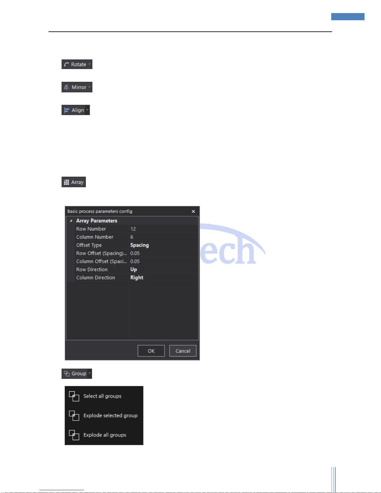
1) :User can adjust the size in proportion of the selected graphic. Click “ ” to set up
parameters.
Page 22
Copyright © WUHAN AU3TECH TRADING CO., LTD
22
SC1000 Fiber Laser Cutting CNC System User’s Manual Version: V1.00
2017 年 3月 27 日
User can choose to zoom the selected graphic in proportion or by certain height/width. User can
also choose the zoom center according to his needs.
2) :User can rotate the selected graphic in any angle.
3) :User can mirror the selected graphic in horizon/perpendicular.
4) :SC1000 support various ways of alignment, includes: “Left aligned”, “Right aligned”,
“Horizontal aligned”, “Top/Bottom aligned”, “Vertical center”, “Center”.
3.2.2.4 Advanced transformation
User can adjust the nested relationship among multi graphics.
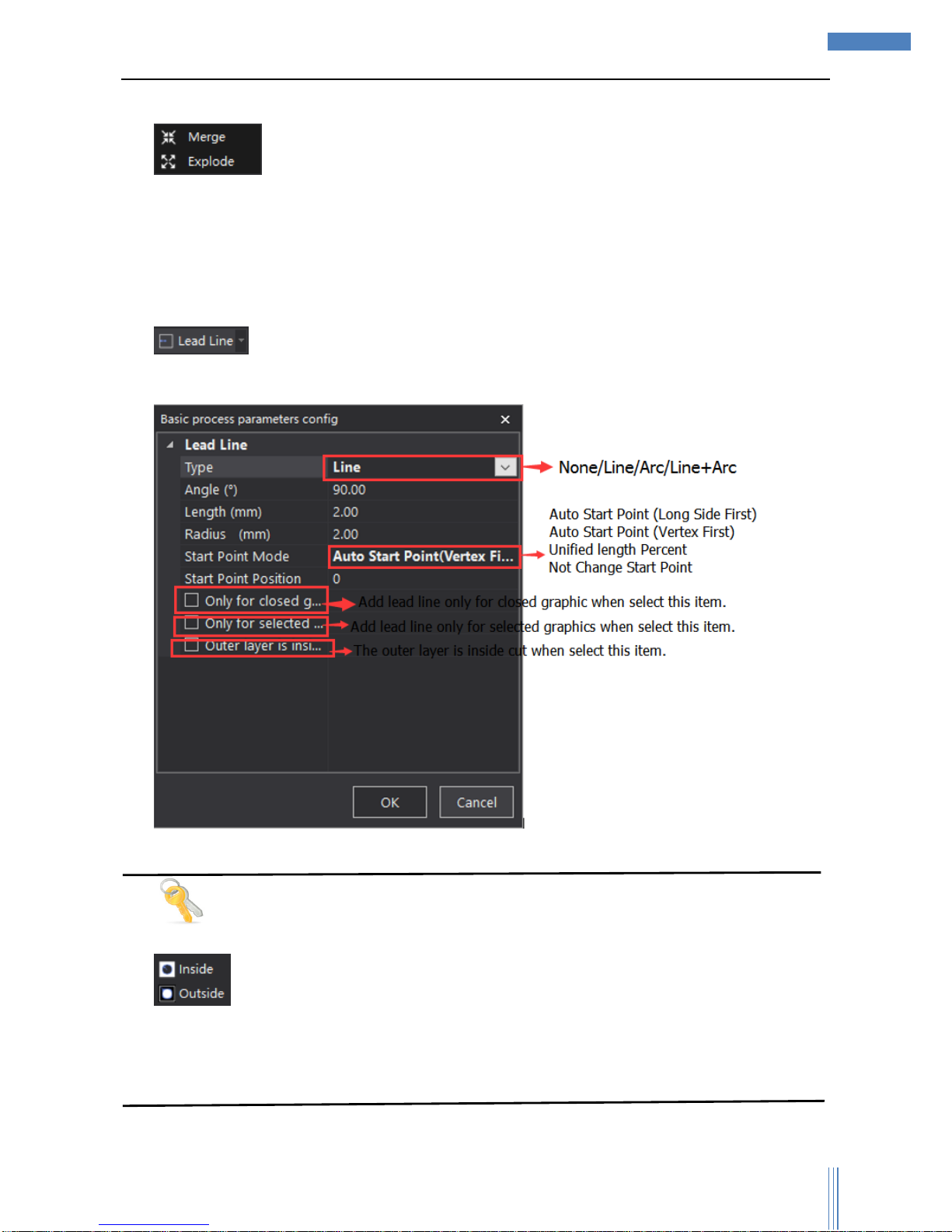
1) :User can array the selected graphic, which often used in cutting one single graphic for
many times.
2) :User can relate multi irrelevant graphics as a whole in one group.
Page 23
Copyright © WUHAN AU3TECH TRADING CO., LTD
23
SC1000 Fiber Laser Cutting CNC System User’s Manual Version: V1.00
2017 年 3月 27 日
User can choose “Select all groups”, “Explode selected group”, “Explode all groups”.
3) :User can merge multi lines/curves and make them a whole and independent
graphic. User can explode one single graphic until it can’t be separated.
3.2.2.5 Basic cutting process
User can set up the path planning/basic process in this part.
1) :User can add lead line to selected graphics, and click the icon to set up the
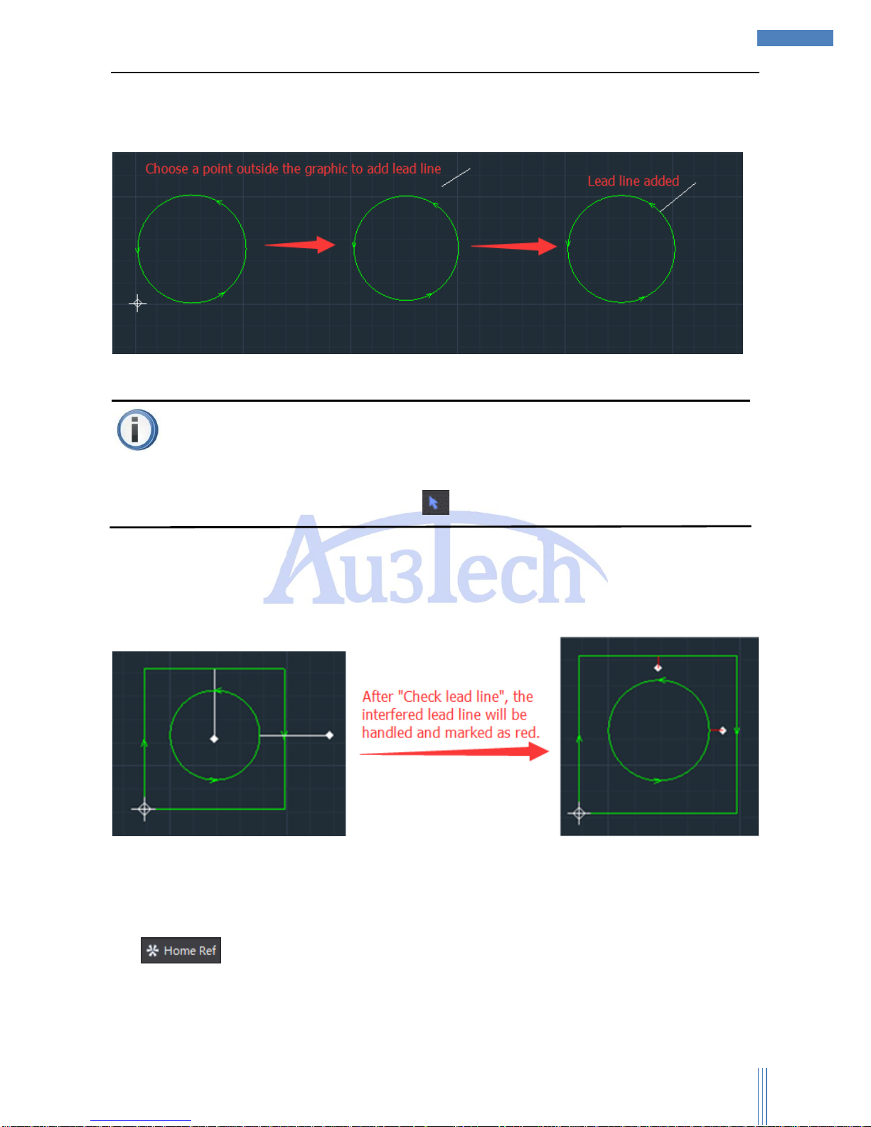
parameters related.
Tips
: SC1000 can recognize the nested relationship among graphics, and the outer layer is
outside cut (default), if the outer layer needs to be inside cut, please select “Outer layer is inside
cut”.
User can change the way of lead line through shortcut-menu.
Page 24
Copyright © WUHAN AU3TECH TRADING CO., LTD
24
SC1000 Fiber Laser Cutting CNC System User’s Manual Version: V1.00
2017 年 3月 27 日
User can click the dropdown menu of lead line to select: “Manual lead line”, “Check lead line”,
“Clear error mark” and “Clear lead line”.
User can add lead line manually through “Manual lead line”. The adding ways shows as below:
Attention
“Manual lead line” can be added continuously, if user wants to dropout the lead line adding, please
select “cancel” through Mouse Right or select .
“Check lead line”:User can check the interfered lead line and clear the error lead line. Please check
all the lead lines again once all have been finished.
“Clear error mark”: User can clear error mark of selected graphic. If user wants to clear all the lead
lines, please click “Select all”.
“Clear lead line”: User can clear the red mark interfering lead line.
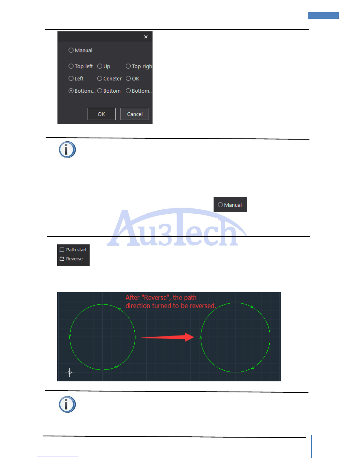
2) :User can set up the docking location of the cutting head after the cutting, that is to say
the zero point of the cutting graphic.
Page 25
Copyright © WUHAN AU3TECH TRADING CO., LTD
25
SC1000 Fiber Laser Cutting CNC System User’s Manual Version: V1.00
2017 年 3月 27 日
Attention
SC1000 use “Floating coordinate system” for cutting, which is the location of cutting head (after
cutting). SC1000 makes the docking location the same as the location of cutting head as default
(after cutting) and at the same time the place of graphics in the view section will be adjusted
accordingly.
User can set up anyplace as the docking location through by clicking the icon of
“Home Ref” and then user would better simulate the cutting process to make sure all the cutting
graphics are inside the workpiece.
3) :User can change the path starting point through “Path start”. After click “Path start”,
user can choose any point on the graphic contour as the current path starting point by Mouse Left.
User can reverse the cutting path by click “Reverse”.
Attention
The places of lead line/gap and other related things will be adjusted accordingly after the changing
Page 26
Copyright © WUHAN AU3TECH TRADING CO., LTD
26
SC1000 Fiber Laser Cutting CNC System User’s Manual Version: V1.00
2017 年 3月 27 日
of the path starting point.
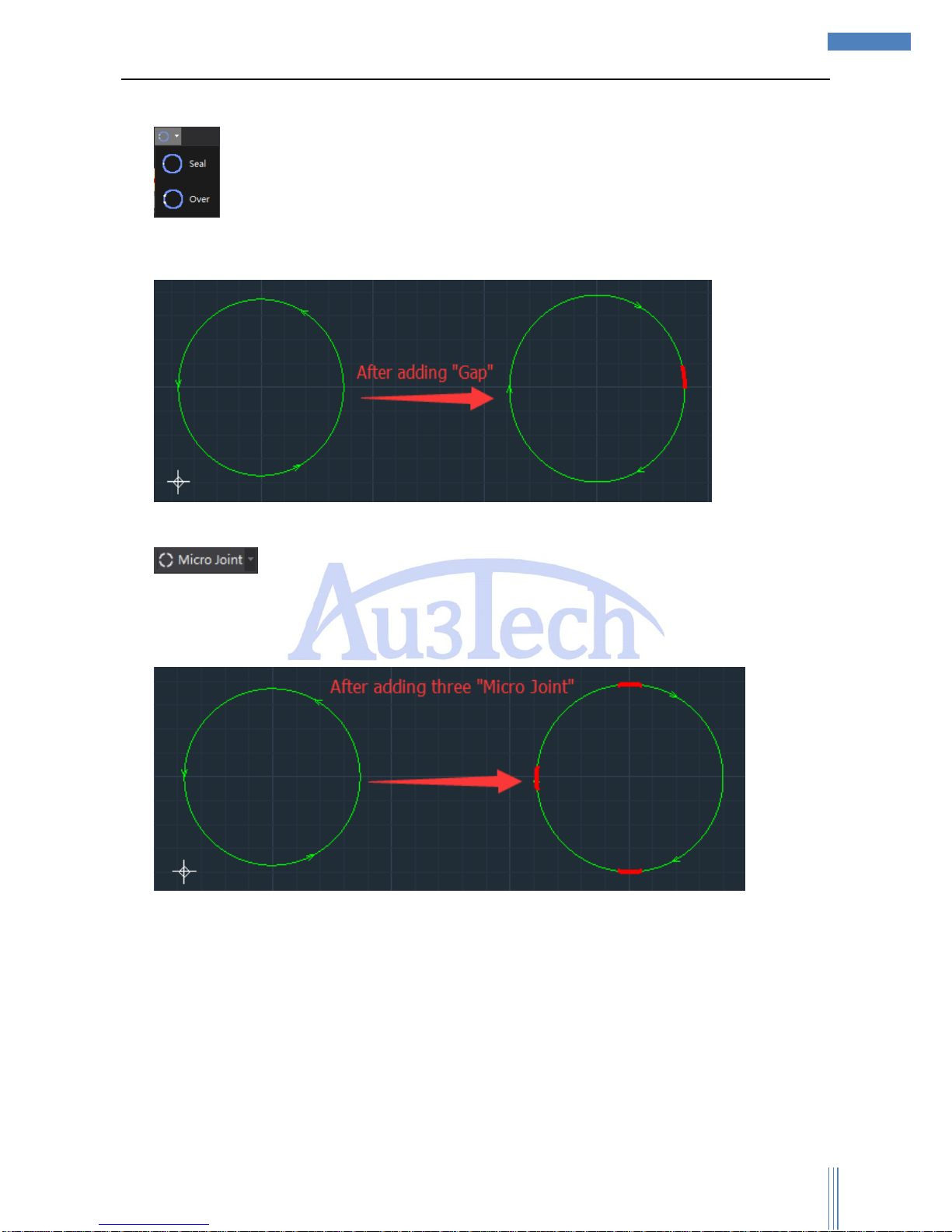
4) :User can reserve gap/line segment of closed graphics in specified size. After adding gap,
there will be red mark on the gap part and the gap part will not be cut during cutting. User can use
this function to stop the cutting part from dropping down.
User can seal the unwanted gap though “Seal”.
5) User can set up several not cutting line segments on the selected graphic contour.
SC1000 support manual micro joint (default) and auto micro joint. After click “Micro Joint”, user can
add micro joint on any point of graphic contour. User also can set up parameters through dropdown
menu.
Auto micro joint: User can set up auto micro joint type/number/length. User also can clear all the
micro joint points by “Clear micro joint”.
3.2.2.6 Advanced cutting process
User can further optimized the path planning or process through this part.
Page 27
Copyright © WUHAN AU3TECH TRADING CO., LTD
27
SC1000 Fiber Laser Cutting CNC System User’s Manual Version: V1.00
2017 年 3月 27 日
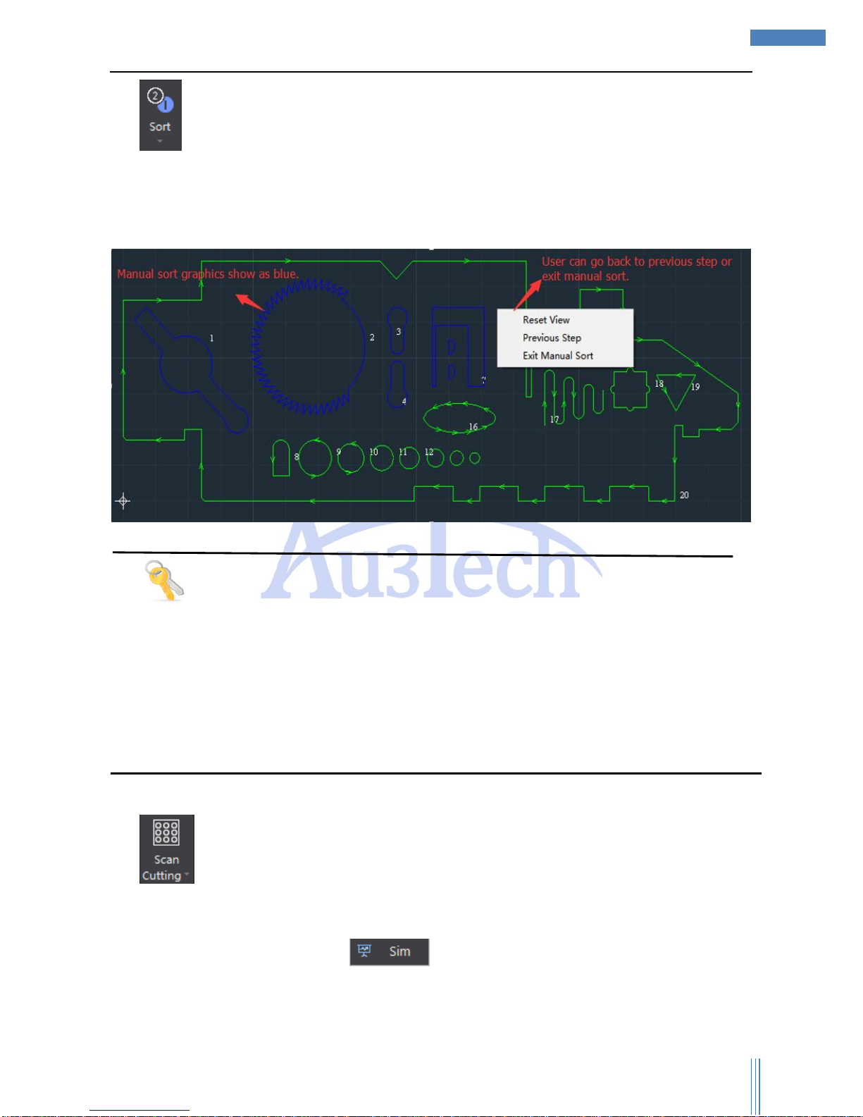
1) SC1000 provides various ways of sorting. User can choose the best one in order to
decrease the length of moving in the air so that to increase the cutting efficiency. User can choose
“Left to right”, “Right to left”, “Bottom to top”, “Top to bottom”, “Nearest”, “Inside to
outside”, “Outside to inside”, “Small graphics priority” and “Manual sort”. “Manual sort”:
User can easily sort according to his needs.
Tips
After sorting, user can also quickly revise the cutting serial number through shortcut-menu.
If user wants to select some graphic as the first/last one to be cut, please select the graphic and
select “First process” or “Last process” through Mouse Right.
SC1000 can auto sort based on nested relationship among graphics, and the graphics surrounded
will always be cut in priority. If the out layer graphic is unclosed curve, then this function will not
work.
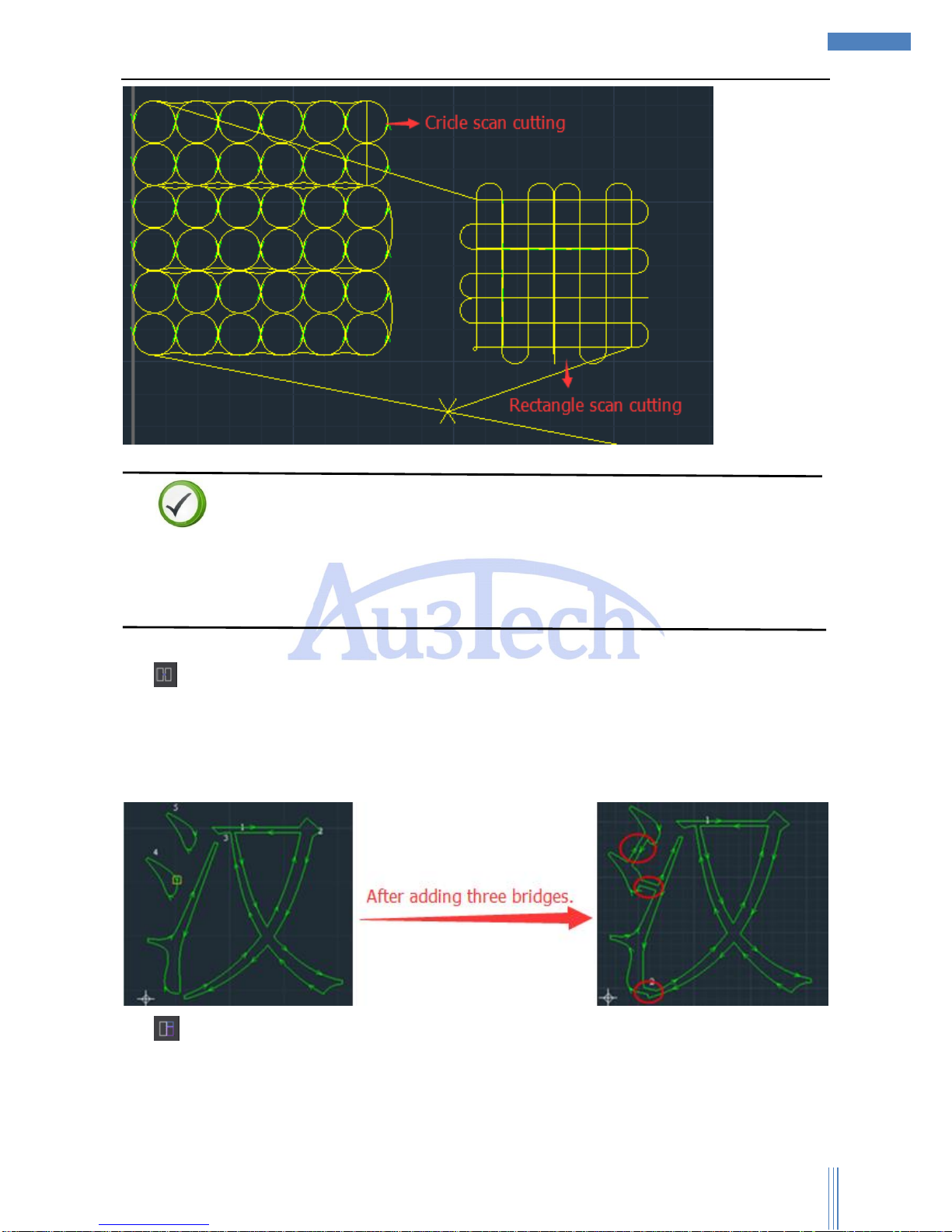
2) “Scan Cutting” is applied for cutting graphics, and SC1000 will choose the best path
planning to improve the efficiency and decrease the time. Select all the graphics (circles/squares in
array) , click “Scan Cutting” then SC1000 will finish planning the path planning, and user can see
the real path planning by clicking “ ”
Page 28
Copyright © WUHAN AU3TECH TRADING CO., LTD
28
SC1000 Fiber Laser Cutting CNC System User’s Manual Version: V1.00
2017 年 3月 27 日
Descriptions
If the selected graphics can’t fit the conditions, then SC1000 can’t do scan cutting, and the message
bar will show a message “The selected graphics can’t fit the conditions!”(新版软件对飞切的图形没有
要求,是否考虑删除本句说明)
3) “Bridge” can be used to connect two independent and closed graphics into one part. This
function is very useful for multi related parts cutting together or AdWords cutting. After selected
“Bridge”, user can set up bridge width. Mouse Left to select one independent contour and move
mouse to select another independent contour then bridge over.
4) “Edge-sharing”: User can use this function to cut graphics sharing their edges so that to cut
the sharing edge one time to save the workpiece.
Page 29
Copyright © WUHAN AU3TECH TRADING CO., LTD
29
SC1000 Fiber Laser Cutting CNC System User’s Manual Version: V1.00
2017 年 3月 27 日
3.2.2.7 Auxiliary
“Auxiliary” part mainly collects some common measure tools.
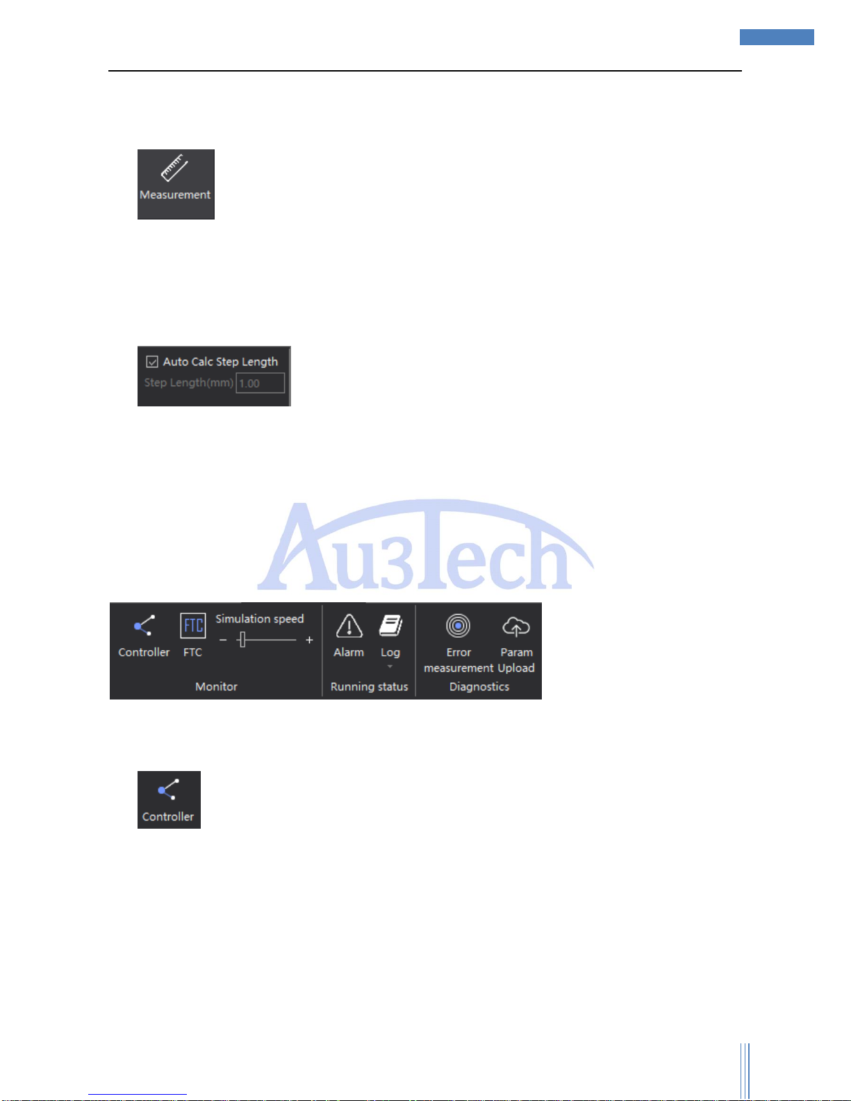
1) : User can use this function to measure the distance between any two points on the
view section. So user can measure the size of cutting graphics before cutting to make sure the
cutting quality.
3.2.2.8 Fine-tuning
1) : User can use this function to micro adjust the place of selected graphics
in fix step length or set up any step length user wants by arrow keys on keyboard.
3.2.3 System analysis
User can monitor the running status of software and hardware of SC1000 to see whether if it’s
running properly or not. If it’s not, it’s convenient for user to find out the real problem and then handle it.
3.2.3.1 Components monitoring
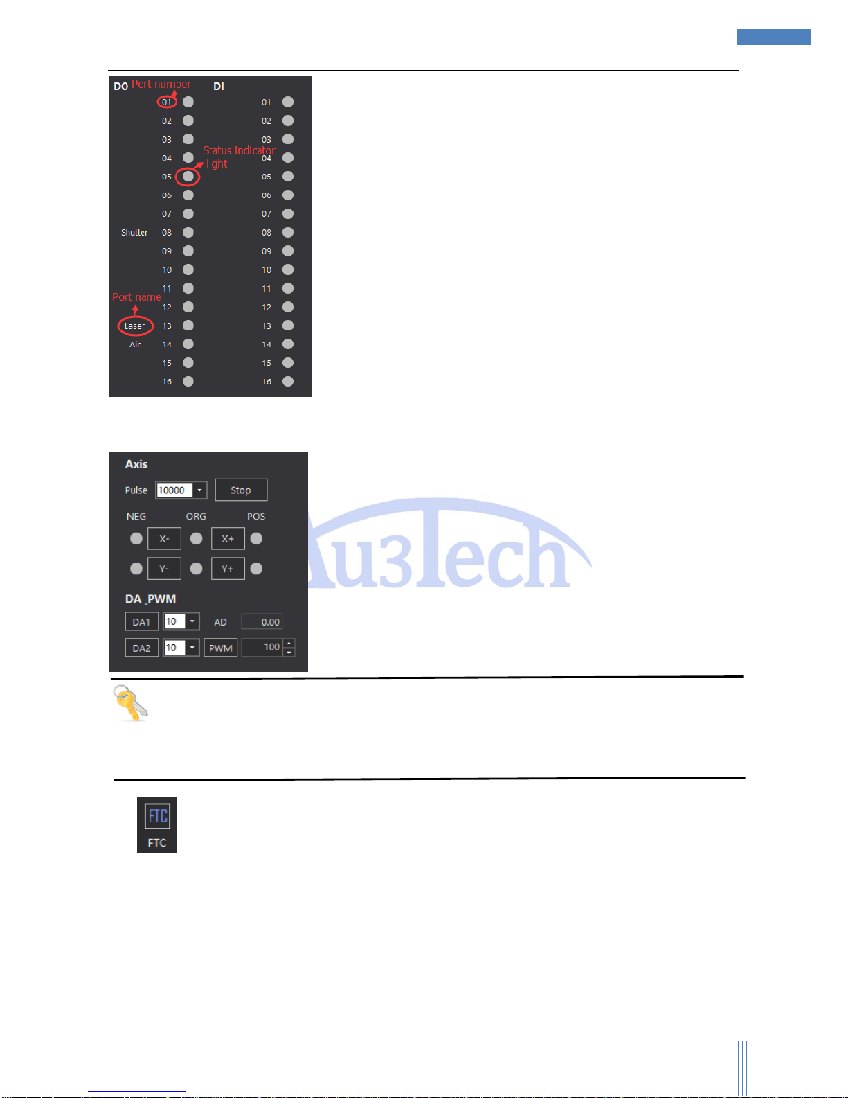
1) is used to monitor the input/output status of CNC system. The light will be green if the
input/output is working properly.
Page 30
Copyright © WUHAN AU3TECH TRADING CO., LTD
30
SC1000 Fiber Laser Cutting CNC System User’s Manual Version: V1.00
2017 年 3月 27 日
The output status of each axis can also be controlled.
Tips
When installing SC1000, user can check each input/output port to see if it’s working properly though
this function. If some port is not working properly, user can use this function to find out.
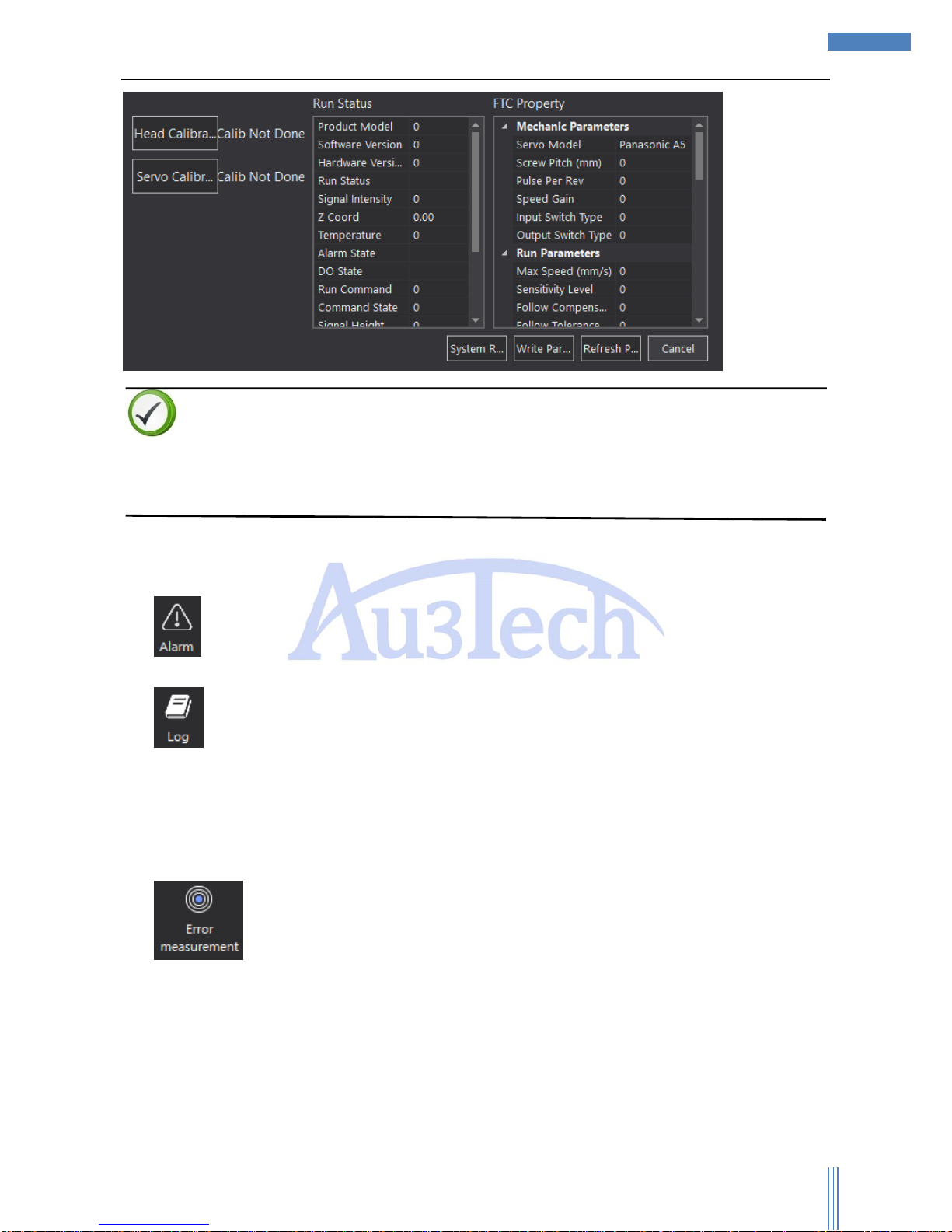
2) “Focus tracking controller” can monitor the running status of Z axis. User can set up the
parameters of FTC91/FTC61. It’ll be much more convenient for user to use our FTC91/FTC61.
Page 31
Copyright © WUHAN AU3TECH TRADING CO., LTD
31
SC1000 Fiber Laser Cutting CNC System User’s Manual Version: V1.00
2017 年 3月 27 日
Descriptions
User can reference the descriptions of FTC to know the meaning of each parameter.
The first time to power on, user needs to use head calibration/servo calibration, or cutting head can’t
follow stably.
3.2.3.2 Running status
1) : User can check the current system alarm by clicking here so that user can easy find out the
problem.
2) : Click here to check the running log, including system alarms/ system messages. This
record can only be kept in 15 days.
3.2.3.3 System diagnose
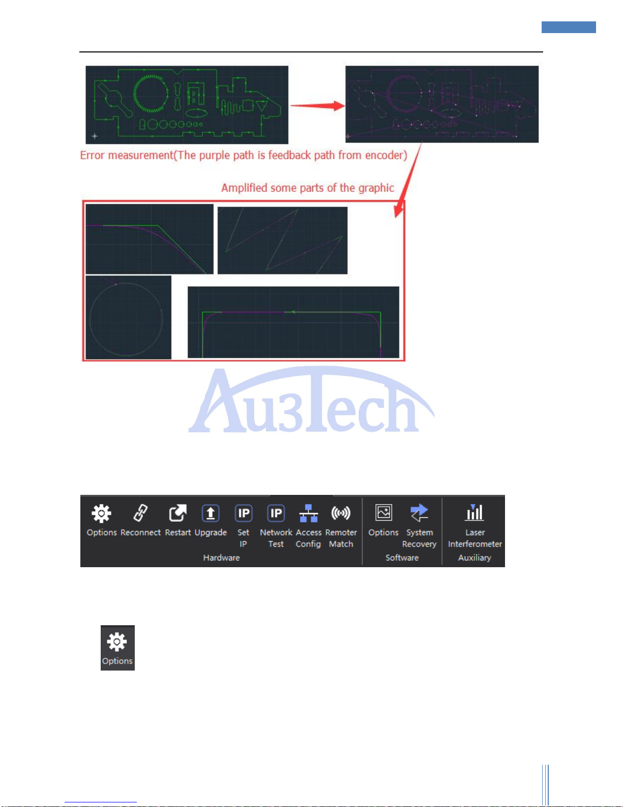
1) : SC1000 can do error analysis such as roundness error by comparing the real running
path with the running path shows on the view section. SC1000 can draw the real running path by
collecting the information of encoder. User can easily debug the machine, and check the running
error of X/Y axis or measure circle and so on. It’s very useful.
Page 32
Copyright © WUHAN AU3TECH TRADING CO., LTD
32
SC1000 Fiber Laser Cutting CNC System User’s Manual Version: V1.00
2017 年 3月 27 日
User can zoom in the view through the middle mouse button and measure the error by measurement
tools.
3.2.4 Advanced
This part mainly collects the tools for hardware configuration/debugging when assembling the
machine. The style of SC1000 and initial settings once been finished, please don’t change them unless
some special occasions happen.
3.2.4.1 Hardware
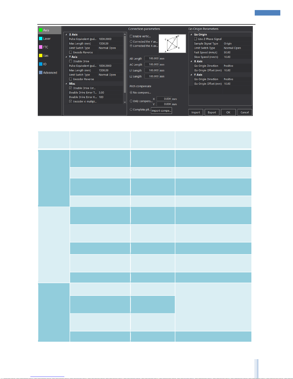
1) : User can set up parameters of Axis/Laser/FTC/Gas/IO/Advanced through this part. Please
carefully set up these parameters. Click “Options” and enter the password, and the initial password
is “0000”.
a) Motion control axis: including the basic parameters and go origin parameters.
Page 33
Copyright © WUHAN AU3TECH TRADING CO., LTD
33
SC1000 Fiber Laser Cutting CNC System User’s Manual Version: V1.00
2017 年 3月 27 日
The descriptions of each axis shows as below :( Y axis has the same parameters as X axis.):
Axis
Parameters
Name
Default Value
Remark
X-Axis
Pulse
Equivalent(pulse/mm)
1000
The number of pulses needed to
run 1mm
Max Length(mm)
1500
Normal open/close
Limit Switch Type
Normal Open
Limit switch type of X-axis should
be the same with Y-axis.
Encode Reverse
Don’t select
Y-Axis
Double Drive
Select
If checked, the Y axis enables
dual drive mode
Pulse
Equivalent(pulse/mm)
1000
The number of pulses needed to
run 1mm
Max Length(mm)
3000
Limit Switch Type
Normal Open
Limit switch type of Y-axis should
be the same with X-axis.
Encode Reverse
Don’t select
Misc
Double Drive Error Alarm
Select
If checked, the software will
alarm and stop when the alarm
condition is reached
Double Drive Error
Tolerance(mm)
3.00
Double Drive Error Keep
Time(ms)
100
Encoder 4 multiplier freq
Select
Page 34

Copyright © WUHAN AU3TECH TRADING CO., LTD
34
SC1000 Fiber Laser Cutting CNC System User’s Manual Version: V1.00
2017 年 3月 27 日
Correction
parameters
Enable vertic
Don’t select
Corrected the Y axis
Corrected the X axis
AB Length(mm)
100.000
AC Length(mm)
100.000
L1 Length(mm)
100.000
L2 Length(mm)
100.000
Pitch compensate
No compensate
Only compensate
X axis 0.000 mm
Y axis 0.000 mm
Complete pitch
compensate
Go Origin
Use Z Phase Signal
Don’t select
Sample Signal Type
Origin
The user can select the limit
signal or the origin signal
Limit Switch Type
Normal Open
Fast Speed(mm/s)
50.00
Slow Speed(mm/s)
10.00
X-Axis
Go Origin Direction
Positive
Go Origin Offset(mm)
10.00
Y-Axis
Go Origin Direction
Positive
Go Origin Offset(mm)
10.00
Attention
Motion control axis’ parameters are basic, please set up properly or it may occur error during
running.
If Y axis is double drive, please select “Double Drive”.
When the feedback direction of encoder is different from the real running direction, please select
“Encoder Reverse”.
SC1000 can support two kinds of axis limited switch: NPN photoelectric switch/ mechanical switch,
user can set up as normal open/close.
Page 35
Copyright © WUHAN AU3TECH TRADING CO., LTD
35
SC1000 Fiber Laser Cutting CNC System User’s Manual Version: V1.00
2017 年 3月 27 日
User can choose origin signal according to real situation, and then connect it with motion control
card. Once origin signal has been set up, the Go Origin direction must be the same as that of Origin,
or Go Origin can’t be finished and even result in damaging to equipment or even hurting people.(“回
原方向必须与原点方向一致”翻译是否准确)
Go Origin speed can’t be too fast or it may go over origin.
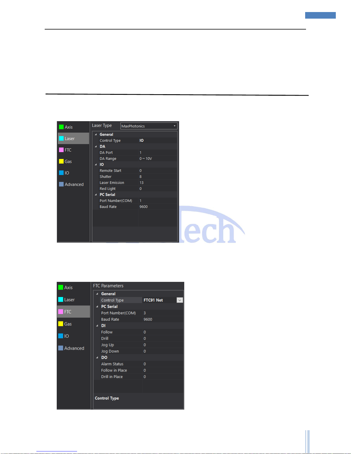
b) Laser: User can set up the communication/connection way. SC1000 support
Raycus/IPG/Semiconductor/MaxPhotonics/Super/TXStar/Others.
c) FTC: User can set up the communication/connection way. SC1000 can connect with our
FTC91/FTC61 by Ethernet/IO port/Serial port/MCC3721H. User can connect them by I/O port if you
use other focus tracking controller.
Page 36
Copyright © WUHAN AU3TECH TRADING CO., LTD
36
SC1000 Fiber Laser Cutting CNC System User’s Manual Version: V1.00
2017 年 3月 27 日
Descriptions
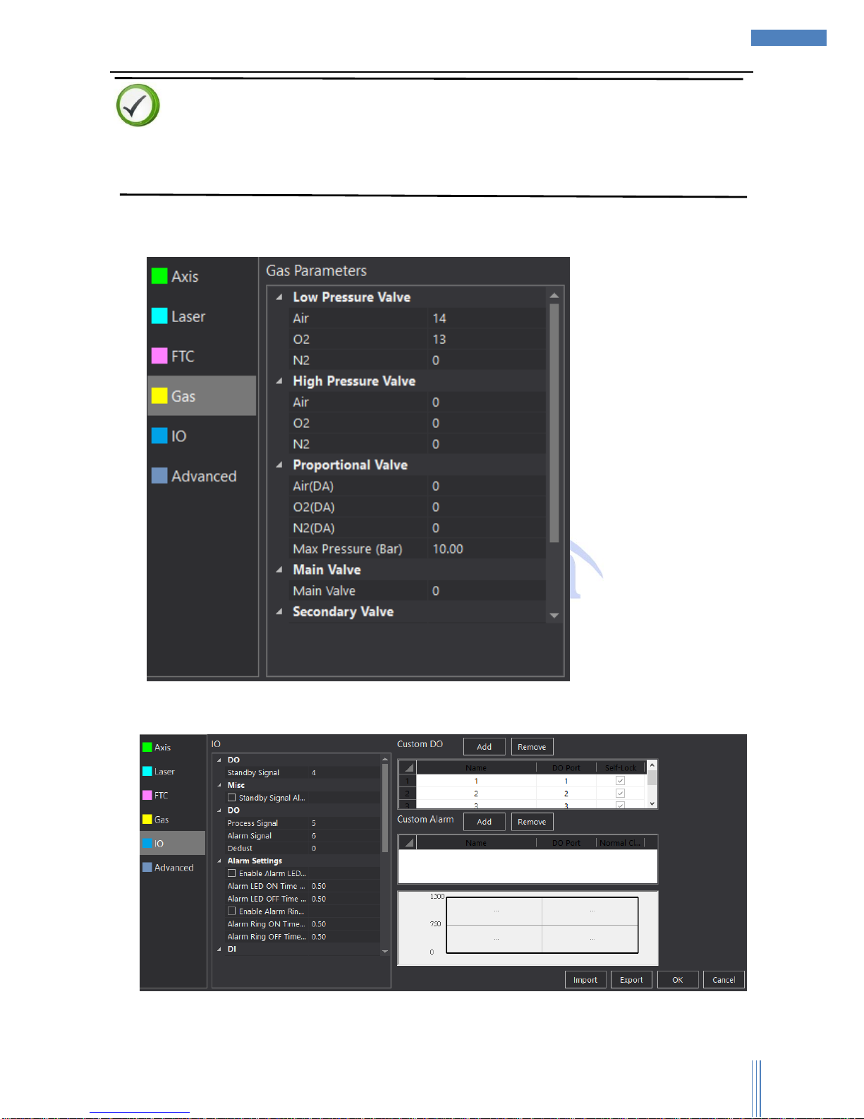
If user choose FTC91, please select “FTC91 Net”. If user choose FTC61, please select “FTC61
IO”/“FTC61 PC Serial”. If user use MCC3721H motion control card, please choose“MCC3721H”.
d) Gas: SC1000 Supports low pressure valve/high pressure valve/proportional valve for Air/O2/N2.
User can set up accordingly.
e) Input/Output: User can set up Standby Signal/ Standby Signal Alarm/Process Signal/Alarm
Signal/Dedust and alarm settings. SC1000 also supports user-define in input/output/alarms.
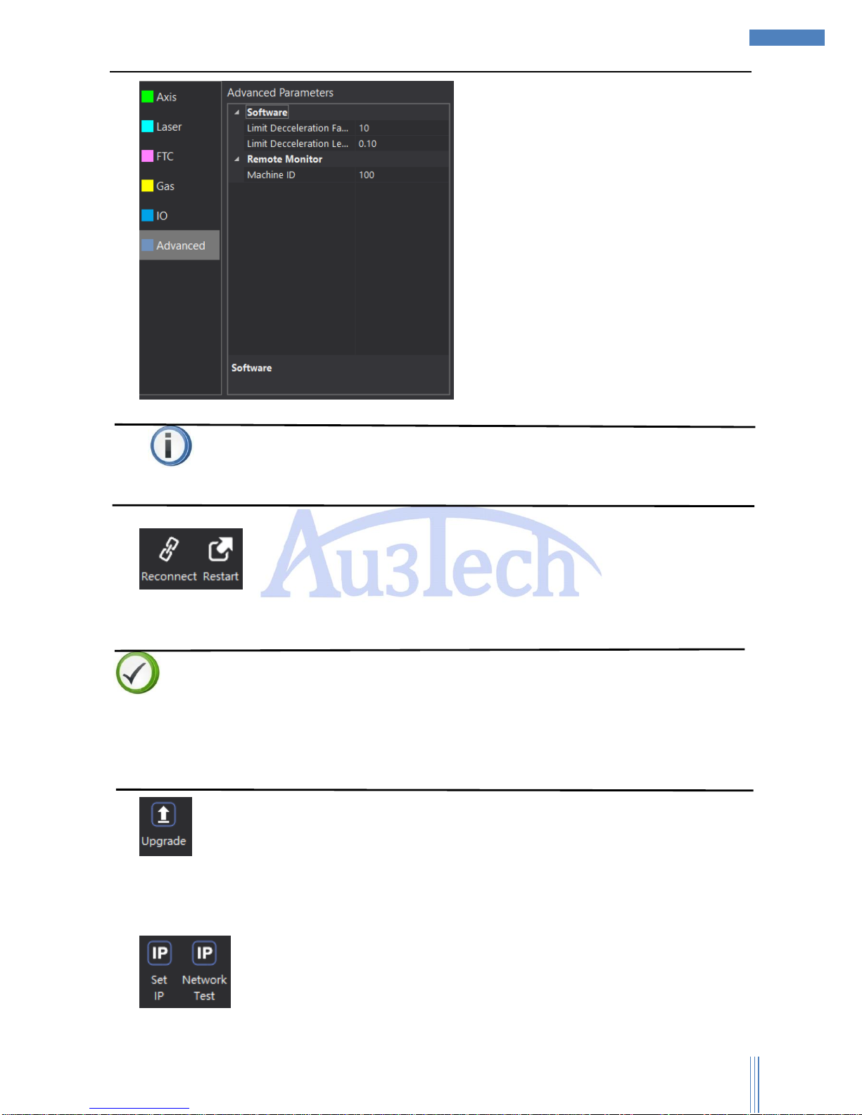
f) Advanced(这一块的文字怎么描述?原始版本没有对这一块的说明)
Page 37
Copyright © WUHAN AU3TECH TRADING CO., LTD
37
SC1000 Fiber Laser Cutting CNC System User’s Manual Version: V1.00
2017 年 3月 27 日
Attention
If some I/O port has not been used, please set this port as “0”.
2) Reconnect: User can reconnect quickly by “Reconnect” when computer is not
well connected with SC1000 for some reasons such as pulling out the Ethernet cable. User can
restart the motion control card by “Restart”.
Descriptions
SC1000 can auto reconnect when recovered the communication parts. If it’s still not connected,
please select “Restart” after selecting “Reconnect”.
If SC1000 runs smoothly, please don’t select “Reconnect” or “Restart”, or SC1000 will be forced to
restart and break the communication.
3) :User can upgrade motion control card by this function. After click “Upgrade”, please select
the program file to upgrade. Please make sure all the relative equipment are power on and SC1000
is open during the upgrading to avoid unpredictable events happening. After upgrading is over, just
reconnect and restart SC1000.
4) : SC1000 can set up IP automatically and test the IP address by “Network Test”.
Page 38
Copyright © WUHAN AU3TECH TRADING CO., LTD
38
SC1000 Fiber Laser Cutting CNC System User’s Manual Version: V1.00
2017 年 3月 27 日
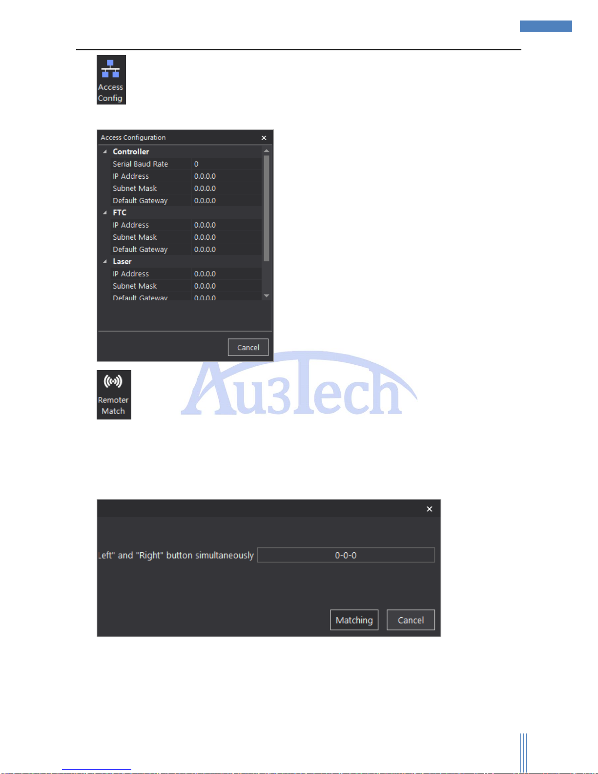
5) :Controller IP address: 10.1.1.168; FTC IP: 10.1.1.169; Laser IP: 10.1.1.170; User don’t need
to set Sub Mask and Default Gateway.
6) : Wireless remoter need to pair up before we can use.
Steps:
Please connect the USB receiver to the computer;
Click “Remoter Match”;
Press “Left” and ”Right” button simultaneously. If there shows a serial number, it means match
succeed.
Page 39
Copyright © WUHAN AU3TECH TRADING CO., LTD
39
SC1000 Fiber Laser Cutting CNC System User’s Manual Version: V1.00
2017 年 3月 27 日
3.2.4.2 Software
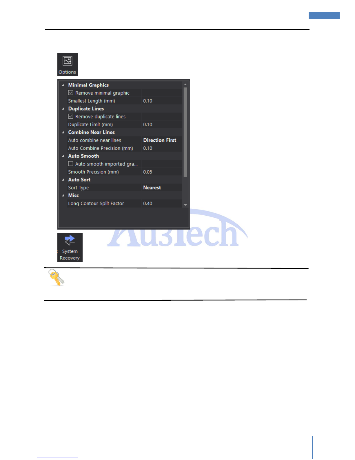
1) , User can preprocessed and optimized the importing graphics according to your needs.
2) : User can do system recovery through here. (自己写的,原版本没有说明,欢迎补充)
Tips
The less the items needed to be preprocessed, the faster the graphics will be importing.
3.2.4.3 Auxiliary(原版本没有说明,欢迎补充)
3.3 View section
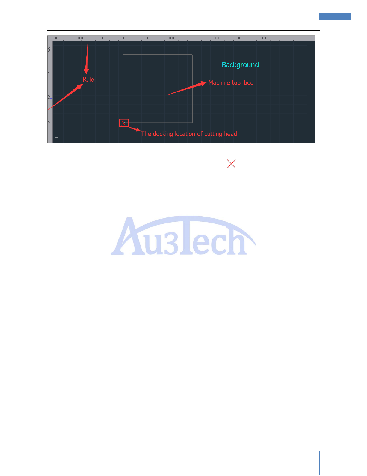
This section mainly display the graphics needed to be processed. User can draw/check graphics
and zoom in/out the graphics by middle mouse button.
Page 40
Copyright © WUHAN AU3TECH TRADING CO., LTD
40
SC1000 Fiber Laser Cutting CNC System User’s Manual Version: V1.00
2017 年 3月 27 日
Coordination: SC1000 will use floating coordination (default), and the docking location of cutting
head is the starting point of the cutting processing (The location of “ ” in the view section.). User can
simulate the cutting process/frame to make sure all the cutting graphics are inside the workpiece.
3.4 Running control option
Running control option is located in bottom-right, including all the running control actions and
parameters. Please get to know each action/function before the cutting process to avoid improper
operation.
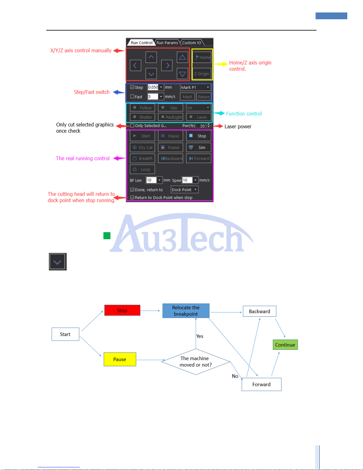
3.4.1 Running control
Each function of running control shows as below:
Page 41
Copyright © WUHAN AU3TECH TRADING CO., LTD
41
SC1000 Fiber Laser Cutting CNC System User’s Manual Version: V1.00
2017 年 3月 27 日
SC1000 supports controlling X/Y/Z axis to move manually. User can set up the moving
pattern/speed by SC1000 (Step/Fast).
User can control some functions separately: Follow/Gas/Air/Shutter/Red-light/Laser.
If the greenlight “ ” of the button goes on, which means the function has been done. About “Laser”,
Mouse Left to open the laser, release it to shut the laser. While other functions need to be switched by
“ ”;
You can reference the chart below to know the running control logic:
1) User can “Pause”/”Stop” the cutting process during cutting. If you choose “Pause”, SC1000 will
stop at the moment and reserve the current cutting information and user can release “Pause” to
continue the cutting (User also can move the cutting head by “Backward”/”Forward” to the proper
location before continuingly cutting.) If user moved the cutting machine after “Pause”, please
Page 42

Copyright © WUHAN AU3TECH TRADING CO., LTD
42
SC1000 Fiber Laser Cutting CNC System User’s Manual Version: V1.00
2017 年 3月 27 日
relocate the breakpoint first then you can continue your cutting process. If user choose “Stop”
manually during cutting process, the current cutting process information will be delate and user
must relocate the breakpoint first in order to find the last cutting location before continuingly cutting.
2) “Dry Cut”: Cut without laser.
3) “Frame”: SC1000 will do the cutting process without laser and Z axis will not follow (default). If user
wants Z axis to follow, please select “Enable follow when dry cut”.
4) “Sim”: SC1000 can simulate laser’s real running path.
5) “Loop”: User can use it to cut one graphic repeatedly.
3.4.2 Running parameters
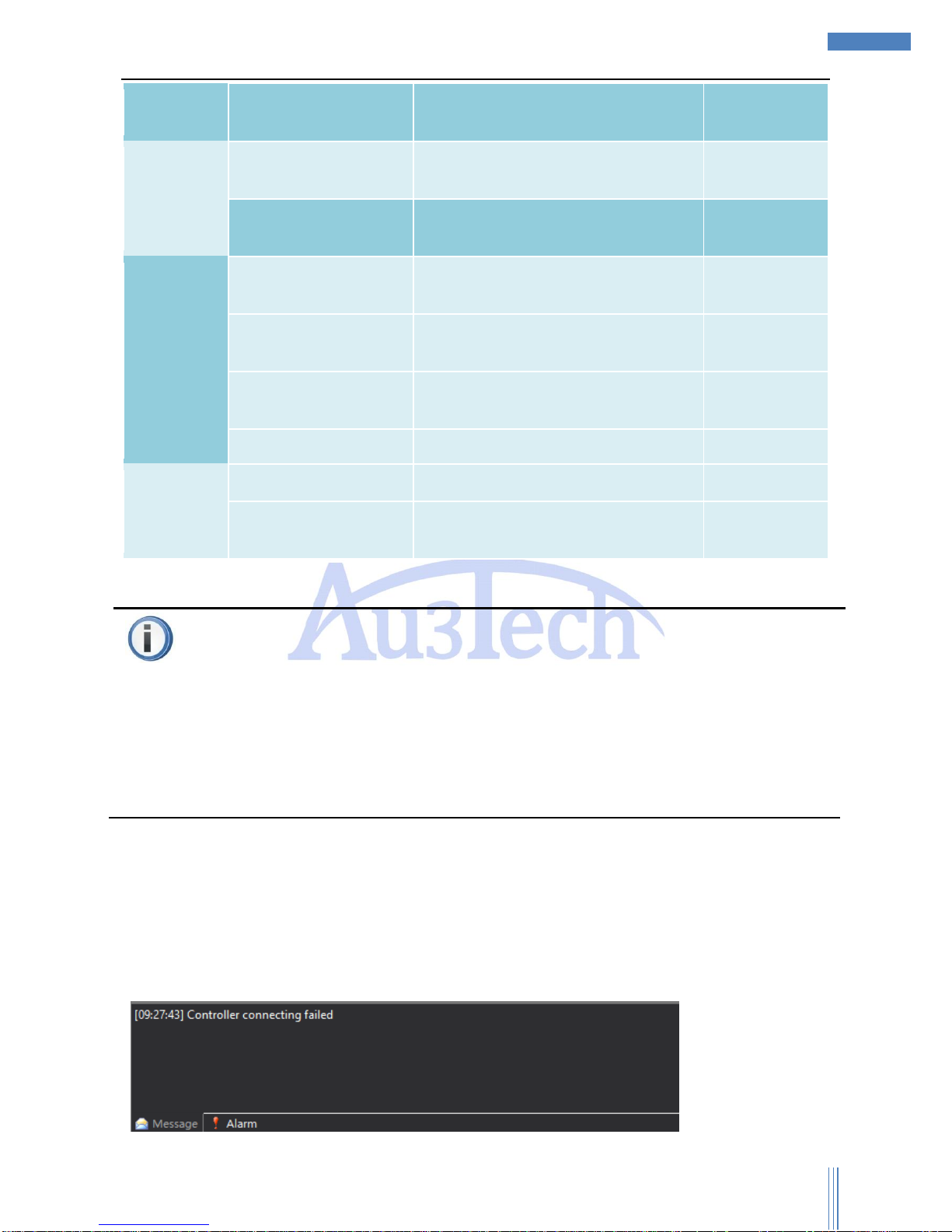
User can set up running parameters through this part. The descriptions of each parameters show as
below:
Name of running parameters
Descriptions
Default value
Run control
Go Frame Speed (mm/s)
Move speed when go frame.
10.00
Move Speed (mm/s)
Move speed without laser.
10.00
Move Acc (mm/s2)
Move accelerated speed without laser.
200.00
Empty Move Acc Time
(ms)
Accelerated time when empty move.
125.00
Cut Acc (mm/s2)
Accelerated speed when cutting.
200.00
Process Acc Time (ms)
Accelerated time when cutting.
125.00
Circle Precision (mm)
0.01
Corner Precision (mm)
0.10
Laser
Control
Laser Freq (Hz)
Laser frequency.
5000
Peak Current (%)
Peak current in proportion.
100
Auto Control Shutter When
Process
Check
Check
Gas Control
Default Pressure (Bar)
4.00
Gas On Delay (ms)
Gas on delay when cutting
0
First Gas On Delay (ms)
First gas on delay when cutting
0
Gas Change Delay (ms)
0
Follow
Control
Short Move Unlift Length
(mm)
10
Enable Frog Style Up
Enable frog style up when move from one
cutting point to another after check.
Page 43
Copyright © WUHAN AU3TECH TRADING CO., LTD
43
SC1000 Fiber Laser Cutting CNC System User’s Manual Version: V1.00
2017 年 3月 27 日
Enable Follow When Dry
Cut
When dry cut, the cutting head will follow
after check.
Process
Clear track line after
process done.
Clear track line after cutting.
Enable software limited
X/Y axis running path will be limited inside
the workpiece after check.
Graphic
Process
Control
Auto distinguish inner
outer before process.
Enable micro-link
deceleration
Micro-link slow down
velocity (mm/s)
10.00
Cool position delay (ms)
100
Unit
Speed Unit
You can choose different speed unit.
mm/s; m/min
Acc Unit
You can choose different accelerated
speed unit.
mm/s2; G
Attention
“Cut Acc”/“Process Acc Time” can directly affect the cutting speed. User can properly increase the
“Cut Acc” and decrease the “Process Acc Time” to improve the running efficiency in the condition
that cutting machine will not shake.
Before starting software stroke limit, SC1000 must do X/Y axis go origin one time, or SC1000 can’t
know the coordinate of cutting machine(机械坐标) and then SC1000 will start software stroke limit
anytime.
Custom IO: User can define I/O port yourself according to your needs.
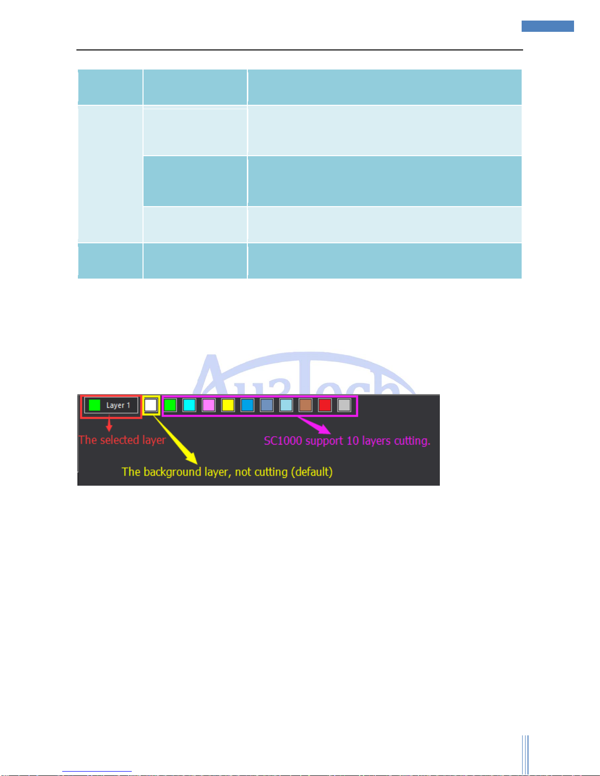
3.5 Message bar
Message bar mainly displays all kinds of information during running process. User can pay attention to
this part when operating SC1000.
Page 44
Copyright © WUHAN AU3TECH TRADING CO., LTD
44
SC1000 Fiber Laser Cutting CNC System User’s Manual Version: V1.00
2017 年 3月 27 日
The descriptions of each message/alarm:
Message
bar
Type
Descriptions
Message
Running status
message
This type of message mainly records all the key running
status, such as: the connecting status of motion control
card/laser/FTC and so on.
Cutting message
This type of message mainly records all the key cutting
information, such as: cutting time/cutting distance/drilling
number/cycle index and so on.
Other message
This type of message mainly records like measurement
results.
Alarm
System alarm
This mainly records system alarm such as limited
alarm/servo input alarm and so on.
And all the messages and alarms can be checked by “SYSTEM ANALYSIS” ->“Log”.
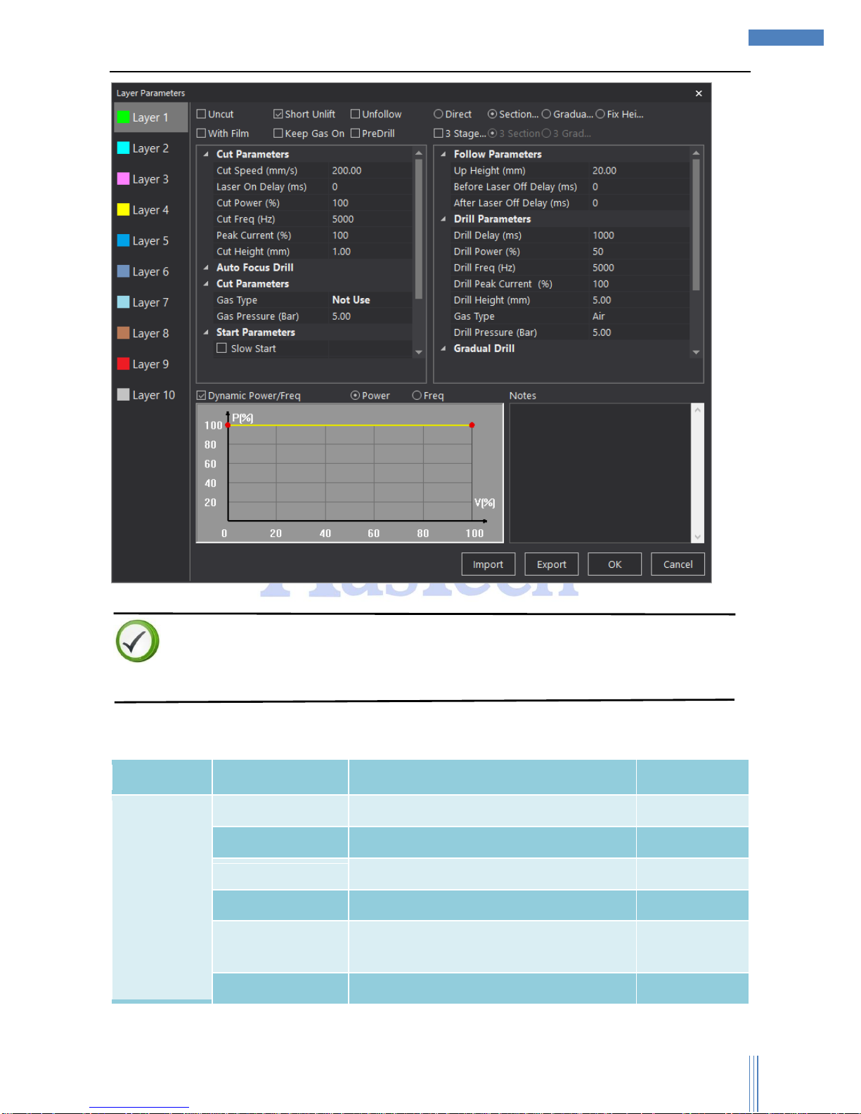
3.6 Layer parameters option
Layer parameters option includes cutting layer process property and one single layer property, user
can quickly set up the parameters accordingly.
SC1000 can auto-match layer property according to user’s selection. Layer parameters: click each
layer to set up the parameters.
Page 45
Copyright © WUHAN AU3TECH TRADING CO., LTD
45
SC1000 Fiber Laser Cutting CNC System User’s Manual Version: V1.00
2017 年 3月 27 日
Descriptions
The selected layer property can be revised any time and works immediately.
The descriptions of each parametes shows as below:
Layer
Name
Descriptions
Default value
Cut
parameters
Cut Speed (mm/s)
Speed when cutting
200.00
Laser on Delay (ms)
Delay time when laser on
0
Cut Power (%)
Laser power in proportion when cutting
100
Cut Frequency (HZ)
Laser frequency when cutting
5000
Peak Current (%)
Laser peak current in proportion when
cutting
100
Cut Height (mm)
The following height when cutting
1.00
Page 46

Copyright © WUHAN AU3TECH TRADING CO., LTD
46
SC1000 Fiber Laser Cutting CNC System User’s Manual Version: V1.00
2017 年 3月 27 日
Gas type
The type of gas when cutting
Not Use
Gas pressure (Bar)
Gas pressure when cutting
5.00
Start
parameters
Slow start
Start slowly when check.
Start length (mm)
Slow start length.
0.00
Start speed (mm/s)
Slow start speed.
0.00
Follow
parameters
Up Height (mm)
Z axis’s up height after cutting.
20.00
Before laser off delay
(ms)
The delay time after cutting but before laser
off.
0
After laser off delay
(ms)
The delay time after laser off.
0
Drill
parameters
Drill delay (ms)
The delay time after arriving at the drill
location.
1000
Drill power (%)
Laser power when drilling.
50
Drill frequency (Hz)
Laser frequency when drilling.
5000
Drill peak current (%)
The peak current in proportion when drilling.
100
Drill height (mm)
The distance between tips and workpiece
when drilling.
5.00
Gas type
The type of gas when drilling.
Air/o2/Not use
Drill pressure (Bar)
The gas pressure when drilling.
5.00
The descriptions of each special process shows as below:
Special process
Descriptions
Uncut
The selected graphic will be cut after check this option.
Short unlift
When the distance between two cutting point is shorter than the unlifted length
that has been set, the cutting head will not lift once check this option.
Unfollow
The Z axis will not follow when cutting once check this option.
Direct cut
The cutting head will go directly to the following location when start cutting
once check this option.
Section drill
Drilling in two different height.
Gradual drill
The cutting head will go directly to the drilling location and start drilling, and
then go to the following location to cut after finish drilling.
Fix height drill
Drilling in some certain distance between tips and workpiece.
Page 47
Copyright © WUHAN AU3TECH TRADING CO., LTD
47
SC1000 Fiber Laser Cutting CNC System User’s Manual Version: V1.00
2017 年 3月 27 日
With film
Cutting with film once check this option. SC1000 will cut the graphic twice,
once to cut the film with a certain height.
Keep gas on
Keep gas on when drilling.
Predrill
Drilling in advance before cutting.
3 stages
drill/section/gradual
Drilling in 3 stages. (暂时没想到更合适的定义)
Descriptions.
Layer parameters will be revised very often during cutting/debugging. So user can adjust all the
parameters according to your needs to achieve the best cutting effects.
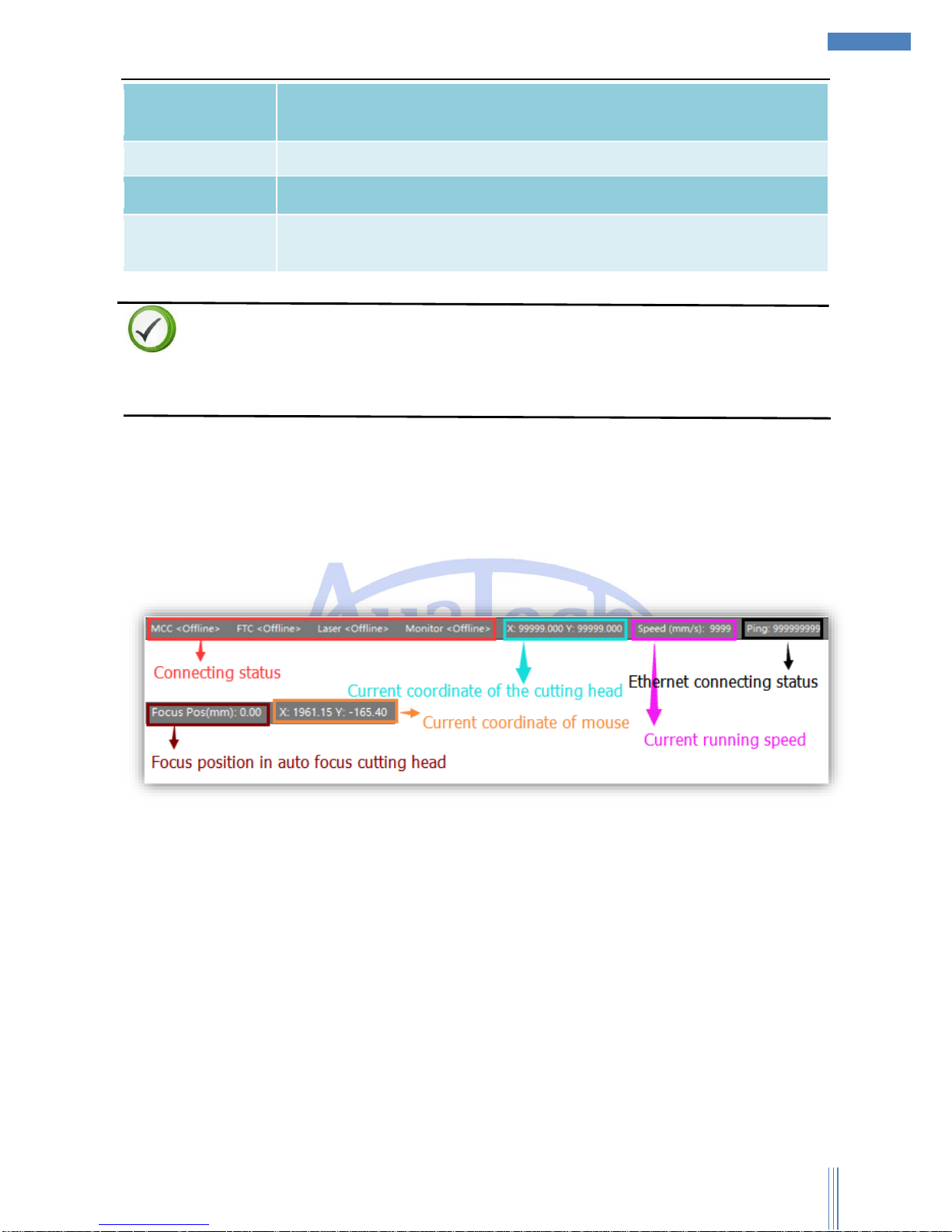
3.7 Status bar
Status bar mainly display the current running status, including the connecting status of motion
control card/FTC/ Laser, X/Y’s current location, current cutting speed and so on, so that user can check it
easily.
Page 48

Copyright © WUHAN AU3TECH TRADING CO., LTD
48
SC1000 Fiber Laser Cutting CNC System User’s Manual Version: V1.00
2017 年 3月 27 日
4 Warning and exceptions handling
4.1 System alarm and descriptions
SC1000 supports lots of alarms and protections accordingly during the cutting process, which can
decrease the opportunity of the equipment damaging or people hurting because of user’s improper
operation. User must know all the alarms and the handling ways.
Alarm lists:
Type of alarm
The content of alarm
Trigger condition
Communication alarm
Hardware is not connected,
please check the controller.
The communication between motion
control card and sc10000 is broken
FTC alarm
The communication between motion
control card and FTC is broken
Laser system alarm
The communication between motion
control card and laser is broken
Laser serial communication
alarm
The communication between motion
control card and laser serial port is
broken
X axis related alarm
(Y1/Y2/W axis related
alarm are similar with
X axis.)
Emergency stop alarm
User pressed the button
X axis servo input alarm
X axis servo driver works improperly.
X axis encoder alarm
X axis encoder has no signal
feedback/the feedback signal is in error.
Y1 axis double drive error
Y1 axis double drive error is out of
range.
X axis hardware positive limit
alarm
The machine moves at the X axis
hardware positive limit.
X axis hardware negative
limit alarm
The machine moves at the X axis
hardware negative limit.
X axis software positive limit
alarm
The machine moves at the X axis
software positive limit.
X axis software negative limit
alarm
The machine moves at the X axis
software negative limit alarm.
Z axis hardware up limit
alarm
The cutting head moves at the Z axis
hardware up limit.
Page 49

Copyright © WUHAN AU3TECH TRADING CO., LTD
49
SC1000 Fiber Laser Cutting CNC System User’s Manual Version: V1.00
2017 年 3月 27 日
FTC related alarm
Z axis hardware down limit
alarm
The cutting head moves at the Z axis
hardware down limit.
Z axis software up limit alarm
The cutting head moves at the Z axis
software up limit.
Z axis software down limit
alarm
The cutting head moves at the Z axis
software down limit.
Z axis servo input alarm
Z axis servo driver works improperly.
Cutting head touch panel
alarm
The tips of cutting head touched the
panel.
Z axis encoder alarm
Z axis encoder has no signal
feedback/the feedback signal is in error.
FTC signal wire alarm
FTC signal wire is note well
connected/or broken.
FTC capacitance variation is
too small
FTC capacitance variation is less than
200.
FTC follow error alarm
FTC follow is out of range.(5mm in
default)
FTC is emergency stop
The running status of FTC is stop,
please go back to origin first.
Laser system alarm
Laser system unknown alarm
Laser system power alarm
Laser system external
interlock alarm
Laser output alarm
Laser system inside interlock
alarm
Laser system power supply
board alarm
Laser system current board
alarm
Laser system unknown alarm
Water cooling machine
alarm
Water cooling machine alarm
Page 50
Copyright © WUHAN AU3TECH TRADING CO., LTD
50
SC1000 Fiber Laser Cutting CNC System User’s Manual Version: V1.00
2017 年 3月 27 日
Descriptions
System alarm has two different alarms, one is a little bit harmful, such as “follow error alarm of
cutting head”, once the warning condition has been cleared, SC10000 will auto clear the alarm. The
other one is more harmful, such as “servo input alarm”, once the warning condition has been
cleared, user must clear the warning manually to make sure the safety of equipment and user.
4.2 Normal exceptions and handling
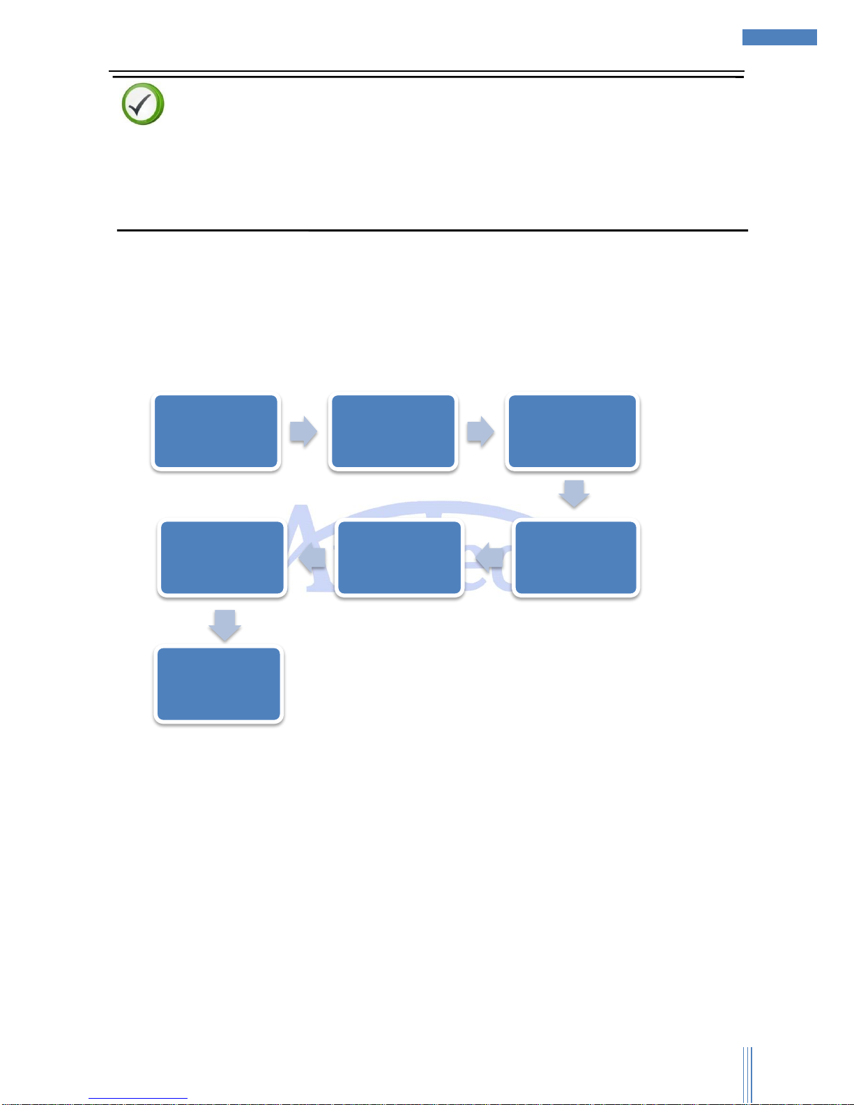
When some normal exceptions occurred, user can do trouble-shooting by SC1000’s diagnose,
which can save user’s time and improve the efficiency.
Graphic 4-1 Normal exceptions troubleshooting flow:
4.2.1 System communication exceptions
SC1000 was designed based on Ethernet, all the equipment are connected through Ethernet.
When SC1000 can’t connect with motion control card or FTC, user can check it out step by step as
below:
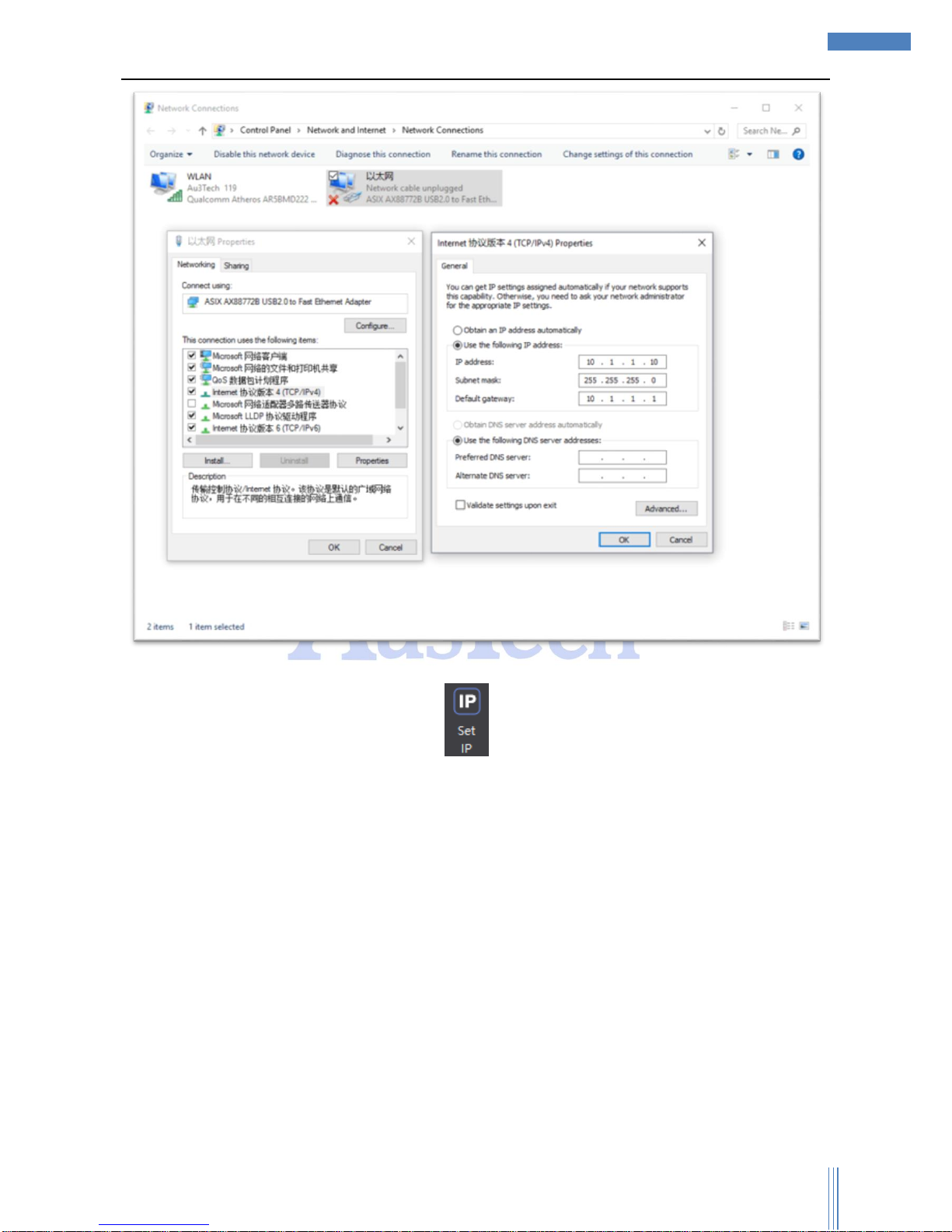
1) Please check whether if the IP has been set.(IP of motion control card/FTC has already been set
before exporting the factory)
When alarm
happened.
Check the
message
bar/log.
Check the
hardware
connecting
status.
Check the
software
configuration.
Clear the
alarm.
Try to run
again.
Over
Page 51
Copyright © WUHAN AU3TECH TRADING CO., LTD
51
SC1000 Fiber Laser Cutting CNC System User’s Manual Version: V1.00
2017 年 3月 27 日
User can quickly set the computer’s IP by “ ”.
2) Please check the indicator light of the Ethernet port. If the indicator light normally on/off, which
means the communications is abnormal. User can check the network cable and try again. SC1000
supports crossed/cross-over cable.
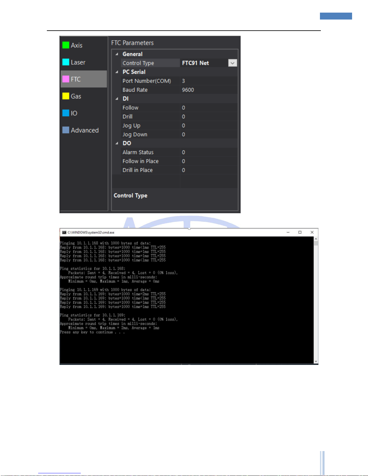
3) when user use FTC91 capacitive height controller, please select “ADVANCED”->“Options”->“FTC”
Control Type -> “FTC91 Net”, if user use FTC61, please select “FTC61 IO”/“FTC61 PC Serial”.
Page 52
Copyright © WUHAN AU3TECH TRADING CO., LTD
52
SC1000 Fiber Laser Cutting CNC System User’s Manual Version: V1.00
2017 年 3月 27 日
4) User can check the communication status by “Network Test”.
4.2.2 Reposition exceptions
Before cutting head “Go Origin”, please make sure the hardware running status/parameters have
already been set properly. If some exceptions happen, please stop running the machine and do not start
“Go Origin” before the exceptions have been cleared. Normal “Go Origin” exceptions and handling
ways:
Page 53

Copyright © WUHAN AU3TECH TRADING CO., LTD
53
SC1000 Fiber Laser Cutting CNC System User’s Manual Version: V1.00
2017 年 3月 27 日
“Go Origin” exceptions
Analysis why
Handling ways
“Go Origin” error
1、Go Origin was set in the wrong direction.
2、X/Y axis’ servo drivers were set in the
wrong direction.
All the directions selected
properly.
The “Home” signal
doesn’t work when Go
Origin.
1、Origin switch broken/the wiring error.
2、Origin’s sampled signal was error.
3、The limited signal wasn’t connected with
the origin signal when making the limited
signal as the original signal.
1 、 Check whether if the
Origin switch and the
indicator light work properly.
2 、 Origin Limit wiring
connected properly.
3 、 Origin sampled signal
selected properly.
SC1000 reminds “X/Y
axis” software limited
alarm
Checked “Enable software limit” before the
cutting head “Go Origin”.
Don’t check “Enable
software limit” before the
cutting head “Go Origin”.
4.2.3 Pulse equivalent setting
Please set up pulse equivalent of each axis properly, or it can be result in running speed error/
accuracy error. The meaning of pulse equivalent: the number of pulse to make the machine run 1mm.
e.g. when X Axis servo motor subdivision is 10000 for running 1 circle, the movement is 10mm, the pulse
equivalent is 10000/10=1000. Pulse equivalent can be set up to 4 digital after decimal point.
4.2.4 Fly-cutting debugging
SC1000 supports all kinds of fly-cutting, please set up all the parameters related properly.
 Loading...