

Page 1

UCrypt
®
IP2IP
UCrypt® Cable Gateways IP to IP
QUICK START GUIDE
www.atxnetworks.com
Page 2

Although every effort has been taken to ensure the accuracy of this document it may be necessary, without notice, to make amendments or correct omissions.
Specications subject to change without notice.
* Any use of the UCrypt product, directly or indirectly, for the decryption and unauthorized reproduction of content that constitutes or may constitute copyright infringement or otherwise infringes on the
proprietary rights of any third party is expressly prohibited. No user of UCrypt shall use UCrypt for any purpose or in any manner which, directly or indirectly, violates the law, violates the proprietary
rights of any other party, or aids in any unlawful act or undertaking including, without limitation, laws governing data privacy, international data transmission, and export of technology or data. Any
multiple systems operator or other similar party (“MSO”) will use the UCrypt product in strict compliance with all applicable laws and in compliance with any agreement in effect between the MSO and
a content provider. In no event shall ATX Networks Corp. or any of its afliates be liable to an MSO, any end user of the UCrypt product, or any other third party, for any claims arising out of or related
to any use or misuse of the UCrypt product in contravention of this disclaimer. It is the express obligation of an MSO to convey this disclaimer to any other end user of the UCrypt product.
®
MDU Solutions
patents. Other non-ATX product and company names in this manual are the property of their respective companies.
and UCrypt
®
are registered trademarks of ATX in the United States and/or other countries. Products or features contained herein may be covered by one or more U.S. or foreign
Page 3

TABLE OF CONTENTS
1. SAFETY ............................................................. 1-1
2. QUICK START GUIDE – READ ME FIRST .................................. 2-1
2.1 Install and Power Up .............................................. 2-1
2.2 Connect the Cables ............................................... 2-1
2.3 Start the UCrypt
2.4 Change Network Settings ........................................... 2-1
2.5 Optionally Import an Existing Conguration File .......................... 2-1
2.6 Select Programs for Processing ...................................... 2-2
2.7 Congure Output Multiplexes ........................................ 2-2
2.8 Assign Programs to Output Multiplexes ................................ 2-2
3. IMPORTANT CONFIGURATION INFORMATION ............................. 3-1
3.1 Support for Two Simultaneous Congurations ........................... 3-1
4. INSTALLATION SUMMARY .............................................. 4-1
4.1 Mounting ........................................................ 4-1
4.2 Equipment Safety Grounding ........................................ 4-1
4.3 Ambient Environment .............................................. 4-1
4.4 Power Requirements .............................................. 4-2
®
Management Interface ............................... 2-1
5. CABLING CONNECTIONS ............................................... 5-1
5.1 Input Ports ...................................................... 5-1
5.2 Output Ports ..................................................... 5-1
6. POWERING UP ........................................................ 5-3
7. MANAGEMENT INTERFACE ............................................. 7-1
7.1 Connect to the Management Interface ................................. 7-1
7.2 Congure the Management Computer Network Port ...................... 7-1
7.3 Log in to the Management Interface ................................... 7-2
8. INPUT ETHERNET VIEW TAB - CONFIGURATION ........................... 8-1
9. OUTPUT MPTS VIEW TAB - CONFIGURATION .............................. 9-1
10. SYSTEM TAB - CONFIGURATION ....................................... 10-1
10.1 Default User Names and Passwords ................................. 10-1
11. CONFIGURATION TAB - CONFIGURATION ................................ 11-1
12. SERVICE & SUPPORT ................................................. 12-1
12.1 Contact ATX Networks ............................................ 12-1
12.2 Warranty Information ............................................. 12-1
MDU Solutions® – UCrypt® IP to IP – Quick Start Guide i
Page 4

This page intentionally left blank
ii MDU Solutions® – UCrypt® IP to IP – Quick Start Guide
Page 5

1. SAFETY
WARNING! FAILURE TO FOLLOW THE SAFETY PRECAUTIONS LISTED BELOW MAY RESULT IN PROPERTY DAMAGE
OR PERSONAL INJURY. PLEASE READ AND COMPLY WITH THE FOLLOWING:
SAFETY GROUND: The connection to earth of the supplementary grounding conductor shall be in compliance with the
appropriate rules for terminating bonding jumpers in Part V of Article 250 of the National Electrical Code, ANSI/NFPA 70, and
Section 10 of Part I of the Canadian Electrical Code, Part I, CSA C22.1.
WATER AND MOISTURE: Care should be taken to prevent entry of splashed or dripping water, other liquids, and physical
objects through enclosure openings.
DAMAGE: Do not operate the device if damage to any components is suspected.
POWER SOURCES: Only connect the unit to a power supply of the type and capacity specied in the operating instructions
or as marked on the device.
NOTE: a) For 115 VAC operation, use the power cord supplied for operation from a 115 VAC source.
b) For 230 VAC operation, use the power cord supplied for operation from a 230 VAC source.
GROUNDING OR POLARIZATION: Electrical grounding and polarization means must not be defeated.
POWER CORD PROTECTION: Care must be taken during installation to route or arrange the power supply cord to prevent
and avoid the possibility of damage to the cord by external objects. Pay particular attention to the exit point from the device
and plug.
CHAPTER 1:
SAFETY
POWER SUPPLY CORD ROUTING: The power supply cord shall not be attached to the building surface, nor run through
walls, ceilings, oors and similar openings in the building structure.
SERVICE: Do not attempt to service the device beyond procedures provided the operating instructions. All other servicing
should be referred to qualied service personnel.
MODIFICATIONS: Modications should not be made to the device or any of its components for applications other than those
specied in the operating instructions.
SAFETY CODES AND REGULATIONS: The device should be installed and operated in compliance with all applicable local
safety by-laws, codes and regulations.
BATTERY REMOVAL AND REPLACEMENT: Disconnect power (AC or DC) from the equipment before battery removal and
replacement. This is accomplished by unplugging the power cord from the power outlet. Replace the battery with Sony part
No. CR2032 or exact replacement only.
CAUTION: Use of a different battery type may present a risk of re or explosion.
BATTERY DISPOSAL: Recycle or dispose of batteries in accordance with the battery manufacturer’s instructions and local/
national disposal and recycling regulations. Please call 1-800-8-BATTERY or go to the website at www.call2recycle.org for
information on recycling or disposing of your used battery.
MDU Solutions® – UCrypt® IP to IP – Quick Start Guide 1-1
Page 6

CHAPTER 1: SAFETY
This page intentionally left blank
1-2 MDU Solutions® – UCrypt® IP to IP – Quick Start Guide
Page 7

CHAPTER 2: QUICK START GUIDE – READ ME FIRST
2. QUICK START GUIDE – READ ME FIRST
UCrypt® IP to IP Encryptor Functionality
This UCrypt device has the following basic features and resources:
• Receives IP multicasts on a Gigabit Ethernet network.
• Allows exible selection of desired programs from the IP multiplexes.
®
• Encrypts the selected programs with Pro:Idiom
• Allows exible assignment of selected programs to output IP multiplexes.
• Outputs IP multicasts on a Gigabit Ethernet network
For detailed information on con guration, go to the ATX website (atxnetworks.com) in the Resources & Support section, User
Documents sub-section to download the Installation & Operation Manual.
This Quick Start Guide will take you through the steps required to get your UCrypt device up and running if you have not done
this before. Follow the steps below:
2.1 Install and Power Up
You may be doing this rst setup in your lab so detailed installation details are not provided here. See the Installation and
Operation Manual for installation details. You can get it from the ATX website (atxnetworks.com) in the Resource & Support
section, User Documents sub-section. You will rst need to get a user name and password from your ATX Networks support
or sales representative and the contact numbers are on this same web page. Refer to “Installation Summary” on page 4-1
for a brief overview of mounting and powering information.
.
NOTE: If the unit is to be mounted in a rack, it is essential to attach the rear mounting ears to
mounting rails to provide support or alternately install the equipment on a well supported shelf.
2.2 Connect the Cables
A computer with web browser and Ethernet network port will be required to con gure the UCrypt device. Establish a network
connection with the supplied crossover network cable. Connect the input and output ports to your GbE switch.
Refer to “5. Cabling Connections” on page 5-1 for more details about cabling.
2.3 Start the UCrypt® Management Interface
The software for con guring the UCrypt Management Interface is provided by a built in secure web server which presents
con guration pages. You will connect with the secure web server at https://192.168.0.23 which is the default address, and log
in to access the Interface.
The UCrypt device will take about 90 seconds to boot up after applying power before you can begin con guration.
Refer to “7. Management Interface” on page 7-1 for basic setup to connect to the Management Interface.
2.4 Change Network Settings
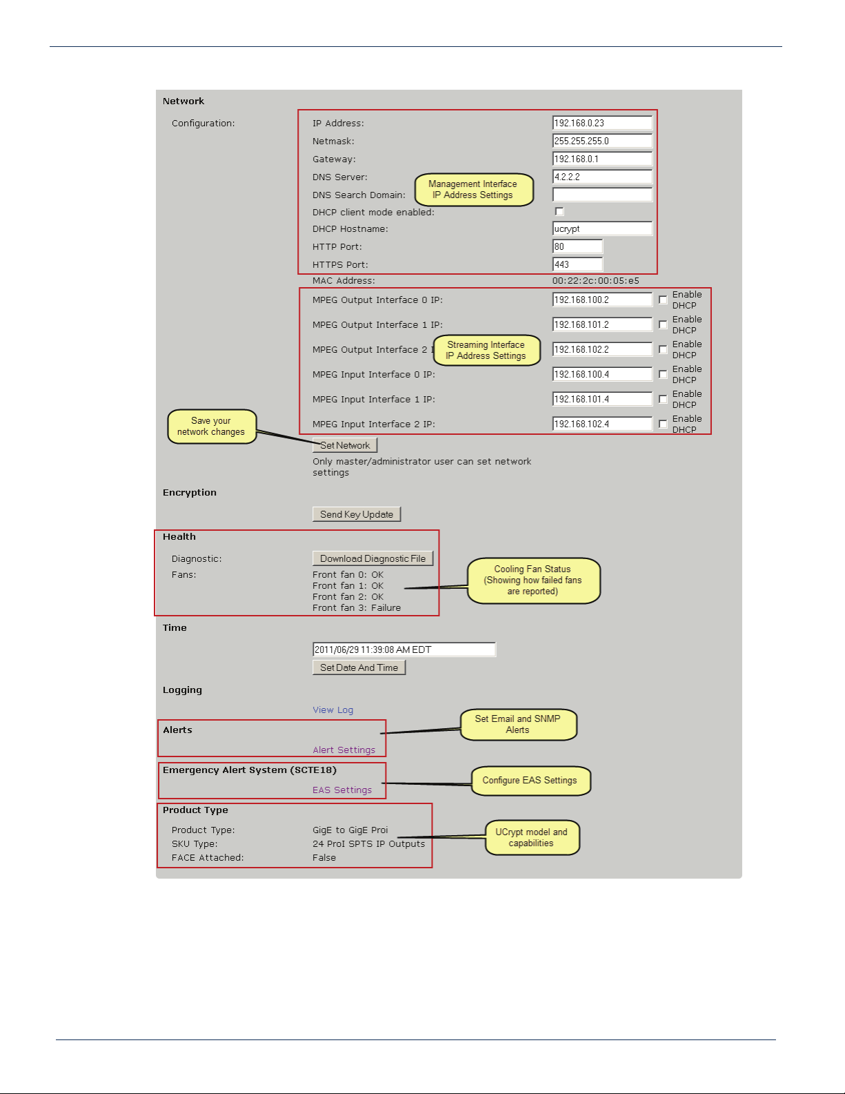
If it is necessary to change the network IP address to access this unit remotely on a network, that is done on the System
con guration tab.
Refer to “10. SYSTEM Tab - Con guration” on page 10-1 to change network IP addresses.
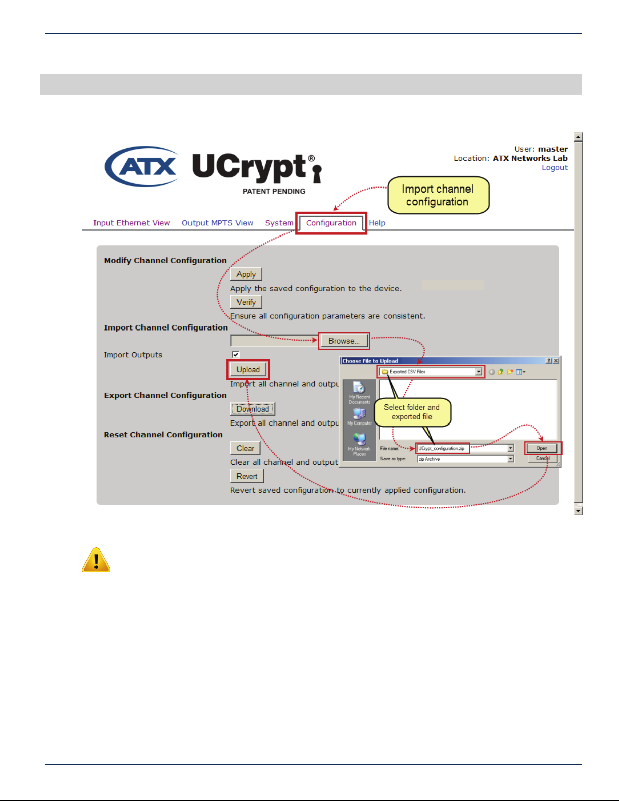
2.5 Optionally Import an Existing Con guration File
The UCrypt device supports mass deployment with an importable/exportable con guration le. If you have a previously
exported con guration le to import, refer to “11. CONFIGURATION Tab - Con guration” on page 11-1.
If you have no le to import skip to Step 12.1 below.
MDU Solutions® – UCrypt® IP to IP – Quick Start Guide 2-1
Page 8

CHAPTER 2: QUICK START GUIDE – READ ME FIRST
2.6 Select Programs for Processing
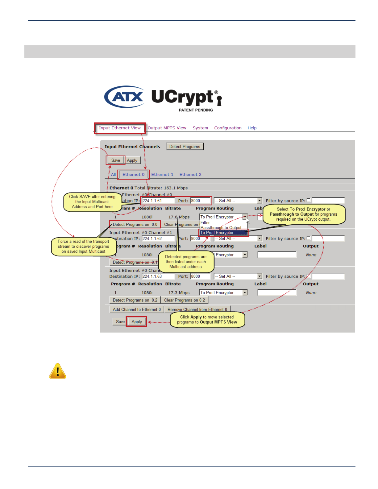
You rst need to dene the incoming multicast addresses and Ports which contain the programs that you want on the UCrypt
device output. Enter the IP address(es) and associated Port number(s), click Save then click the Detect Programs button to
read the Transport Stream(TS) PAT and PMT Tables. Only programs that are in the clear on the input may be selected to be
processed by the UCrypt device. Each program on each multicast will have an accompanying drop down dialog box with 3
options:
• Filter
Program is ignored by UCrypt device and not passed to the output.
• Passthrough to Output
Program is passed to the output without encryption applied.
• To Pro:I Encryptor
Program is encrypted with Pro:Idiom before being sent to output.
Refer to “8. INPUT ETHERNET VIEW Tab - Conguration” on page 8-1 for a summary of steps to select programs.
2.7 Congure Output Multiplexes
You need to specify the IP Address of the output multiplexes.
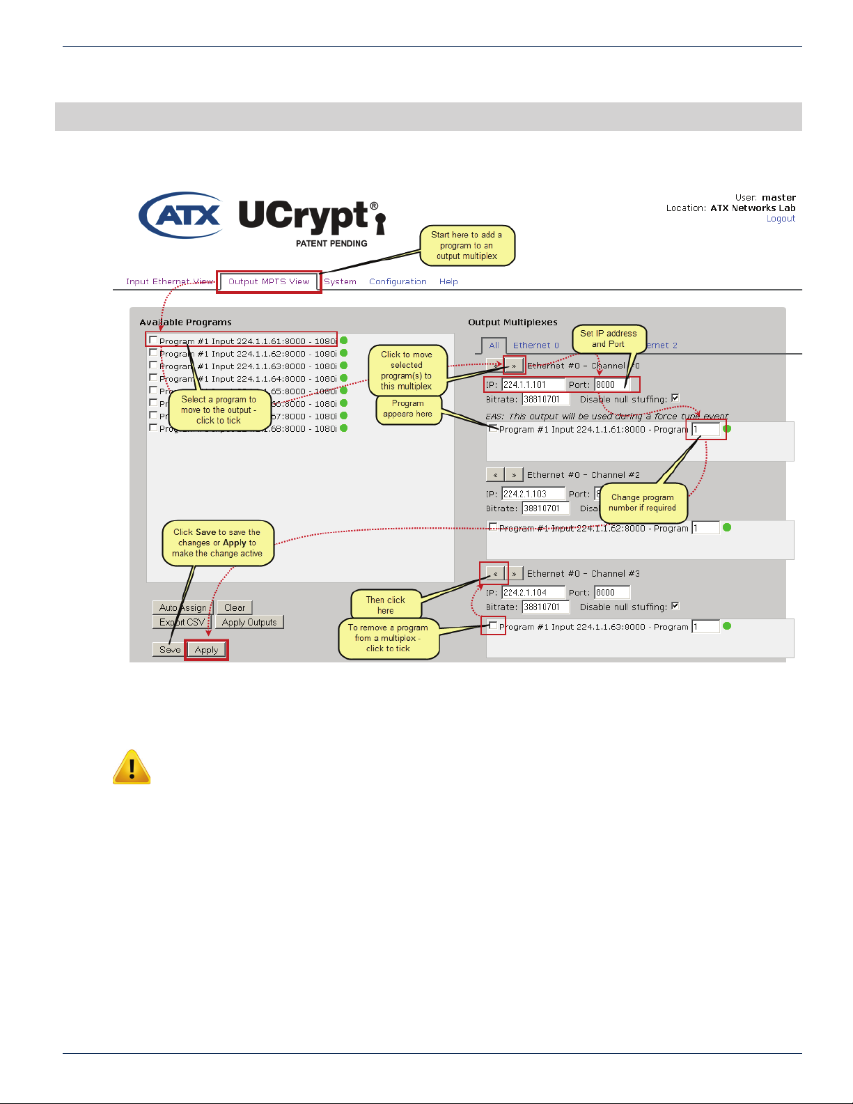
Refer to “9. OUTPUT MPTS VIEW Tab - Conguration” on page 9-1 for more details.
2.8 Assign Programs to Output Multiplexes
Finally, the programs selected on the Input Ethernet View tab are assigned to output multiplexes. Pro:Idiom encryption is
automatically done if the program was selected with the “To Pro:I Encryptor” routing. You may combine encrypted and non-
encrypted programs in the same output multiplex. Depending on the model of UCrypt device ordered, you may either build
SPTS or MPTS multiplexes. The MPTS model may also be used to build SPTS multiplexes.
Refer to “9. OUTPUT MPTS VIEW Tab - Conguration” on page 9-1 to assign selected programs to output IP multiplexes.
That’s it, you’re done
If you followed all the Read Me First directions, you should have programs on the IP output channels that you congured. Use
an IPTV or computer with media player such as VideoLAN to view programs that are in the clear and an appropriate Pro:Idiom
compatible TV or STB with built-in Pro:Idiom to view encrypted programs. Download the full Installation & Operation Manual
from the ATX website (atxnetworks.com) in the Resources & Support section, User Documents sub-section for more details
than are presented here. Click the Help tab to download it to your Management Computer.
2-2 MDU Solutions® – UCrypt® IP to IP – Quick Start Guide
Page 9

CHAPTER 3: IMPORTANT CONFIGURATION INFORMATION
3. IMPORTANT CONFIGURATION INFORMATION
3.1 Support for Two Simultaneous Con gurations
As work on con guration progresses, changes will need to be made to multiple pages in the Management Interface. As work is
completed on each page, the changes must be saved and there is a Save button conveniently located on every con guration
page where con guration changes need to be saved. If changes are made and you navigate away from the page without
saving, the changes may be discarded.
When you are satis ed that all con guration changes on the UCrypt device are complete and correct, click the Apply button
located by the save buttons on any page, they all do the same thing. There is no need to apply the con guration as you
complete work on each page. You may Save your work as you go and Apply the con guration when completed.
3.1.1 Saved Con guration
This can be thought of as a work in progress and any changes can be made in the con guration without affecting
how the UCrypt device is currently working and providing services. This saved con guration can be discarded at
any time without affecting the working UCrypt device con guration or can be ‘Applied’ to make it the new working
con guration. To discard your con guration changes browse to the Con guration tab and click the Revert button.
The Revert action is not service affecting.
3.1.2 Applied Con guration
This is the working con guration that is currently being used to provide the desired services to the output and
regardless of the changes made in the Management Interface as discussed above, changes do not take effect until
the Apply button is clicked and the con guration is applied.
During con guration, while changes are being made, the saved con guration and the applied con guration differ by the
changes that have been made and saved since last clicking ‘Apply’. After the Apply button is clicked, the saved con guration
and the applied con guration are identical.
NOTE: Clicking the Apply button will cause a service interruption while the UCrypt device re-
provisions itself with the new working confi guration. It is best to make all changes necessary on all
confi guration pages and apply the changes when completed.
MDU Solutions® – UCrypt® IP to IP – Quick Start Guide 3-1
Page 10

CHAPTER 3: IMPORTANT CONFIGURATION INFORMATION
This page intentionally left blank
3-2 MDU Solutions® – UCrypt® IP to IP – Quick Start Guide
Page 11
4. INSTALLATION SUMMARY
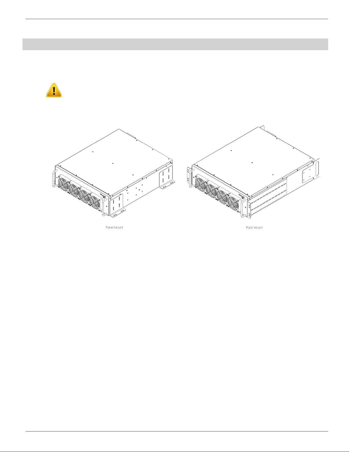
4.1 Mounting
NOTE: If the UCrypt unit is to be mounted in a rack, it is essential to attach the rear mounting
ears of the unit to rear mounting rails to provide support or alternately install the equipment on a
well supported shelf
Rack mount brackets are provided with the UCrypt device for mounting in a standard EIA 19” rack. Brackets are also provided
for mounting the UCrypt device to a vertical backboard for sites where no rack mounting facilities exist.
CHAPTER 4: INSTALLATION SUMMARY
4.2 Equipment Safety Grounding
It is imperative that the UCrypt device housing be connected to a permanent building ground in a manner that will ensure that
the exposed metal parts are constantly connected to ground even when the power cord may be disconnected temporarily. A
grounding lug is provided on the rear panel to conveniently effect such a connection. The following guidelines are provided to
clarify the requirements for the installation to meet UL, CUL and CB standards. The use of the words “Ground” and “Earth” as
well as “Grounding” and “Earthing” may be used interchangeably and in this context, have the same meaning.
1. The supplementary equipment grounding conductor is to be installed between the UCrypt device rear panel ground
connector and earth, that is, in addition to the equipment ground conductor in the power supply cord.
2. The supplementary equipment grounding conductor may not be smaller in size than the branch-circuit supply
conductors or a minimum #14 AWG. The supplementary equipment grounding conductor is to be connected at the
rear panel terminal provided, and connected to earth in a manner that will retain the earth connection when the power
supply cord is unplugged. The connection to earth of the supplementary grounding conductor shall be in compliance
with the appropriate rules for terminating bonding jumpers in Part V of Article 250 of the National Electrical Code,
ANSI/NFPA 70, and Section 10 of Part I of the Canadian Electrical Code, Part I, CSA C22.1.
3. Termination of the supplementary equipment grounding conductor may be made to building steel, to a metal electrical
raceway system, or to any grounded item that is permanently and reliably connected to the electrical service
equipment earth.
4. Bare, covered or insulated grounding conductors are acceptable. A covered or insulated grounding conductor shall
have a continuous outer nish that is either green, or green with one or more yellow stripes.
4.3 Ambient Environment
The UCrypt device is designed to operate to speci cation in an ambient room temperature of 0°C to +50°C (+32°F to +122°F)
however it is recommended that it is installed in an environment that approximates normal room temperature to ensure proper
long term operation.
MDU Solutions® – UCrypt® IP to IP – Quick Start Guide 4-1
Page 12

CHAPTER 4: INSTALLATION SUMMARY
4.4 Power Requirements
The UCrypt device is designed with an autosensing switching type power supply which can operate on a wide range of input
voltages from 115 VAC to 230 VAC. There is no need to congure the power supply to operate on any voltage in this range.
The power cord provided with the UCrypt device is a North American conguration with a NEMA 5-15 grounded plug for 115
VAC. If it is necessary to operate the UCrypt device on 230 VAC, the installer must obtain an IEC cord with a NEMA 6-15
grounded plug for use in North America.
4-2 MDU Solutions® – UCrypt® IP to IP – Quick Start Guide
Page 13
5. CABLING CONNECTIONS
5.1 Input Ports
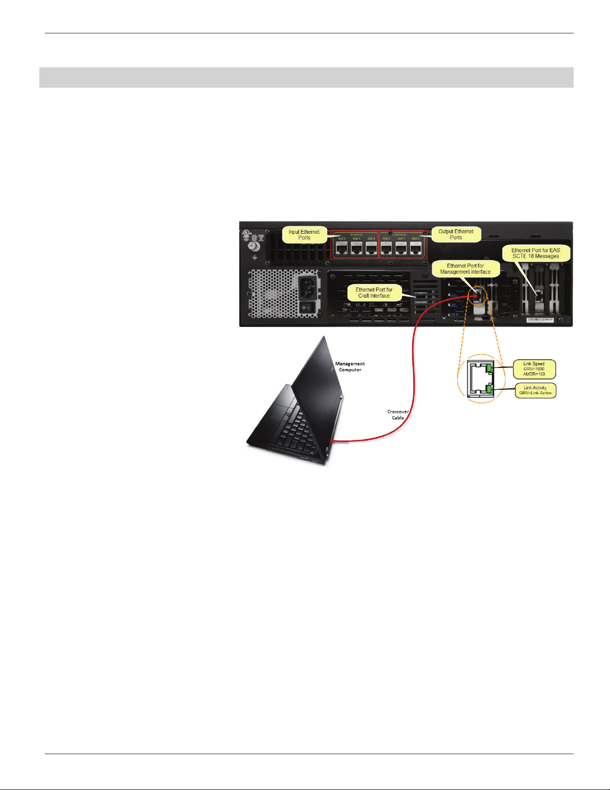
The IP multicasts presented to the UCrypt device must be available on a GbE network switch or router and programs within
the multicasts must be in the clear to be processed by the UCrypt device. No encrypted multiplexes may be passed through
this UCrypt device. The input ports on the UCrypt device are GbE only, autosensing. Use standard straight through wired
cables of Cat5e quality or better to connect the 3 input and 3 output ports to available network switch ports. Each input port is
a unique physical input and can be used to receive up to 16 multicasts of 38.8 Mb/s or an aggregate of 620 Mb/s of smaller
size multicasts. If the UCrypt device model is the 8 or 16 Output multiplex model, then there is only a need to connect to one
GbE input port.
5.2 Output Ports
Output multicasts will be presented
on the physical port that they are
de ned on in the Output MPTS View
and only 8 multicasts may be de ned
for each output port. If there are
multicasts de ned on physical ports
be sure to connect those physical
ports to the network Ethernet switch.
Each physical output port is capable
of up to 8 multicasts of 38.8 Mb/s
data rate.
CHAPTER 5: CABLING CONNECTIONS
UCrypt® Connections to the Management Computer
MDU Solutions® – UCrypt® IP to IP – Quick Start Guide 5-1
Page 14

CHAPTER 5: CABLING CONNECTIONS
This page intentionally left blank
5-2 MDU Solutions® – UCrypt® IP to IP – Quick Start Guide
Page 15

6. POWERING UP
NOTE: The factory default confi guration is that all IP output streams are disabled so no unintended
output into the distribution network is possible. If the UCrypt device has been pre-provisioned
elsewhere then before powering, ensure that the network output cables are disconnected from the
distribution network to avoid unintentional service outages if there are overlaps between the output
IP addresses and existing services on the network.
Apply power and turn on the rear panel switch below the power receptacle. Boot-up will take approximately 90 seconds.
CHAPTER 6: POWERING UP
MDU Solutions® – UCrypt® IP to IP – Quick Start Guide 5-3
Page 16

CHAPTER 6: POWERING UP
This page intentionally left blank
5-4 MDU Solutions® – UCrypt® IP to IP – Quick Start Guide
Page 17
7. MANAGEMENT INTERFACE
7.1 Connect to the Management Interface
Minimum Management Computer Requirements
®
• Computer running Windows
• Ethernet Network port available
• Web browser such as Internet Explorer®, Firefox® or similar
• Adobe Reader for reading this manual
• Notepad or text editor for capturing text and logs
7.2 Congure the Management Computer Network Port
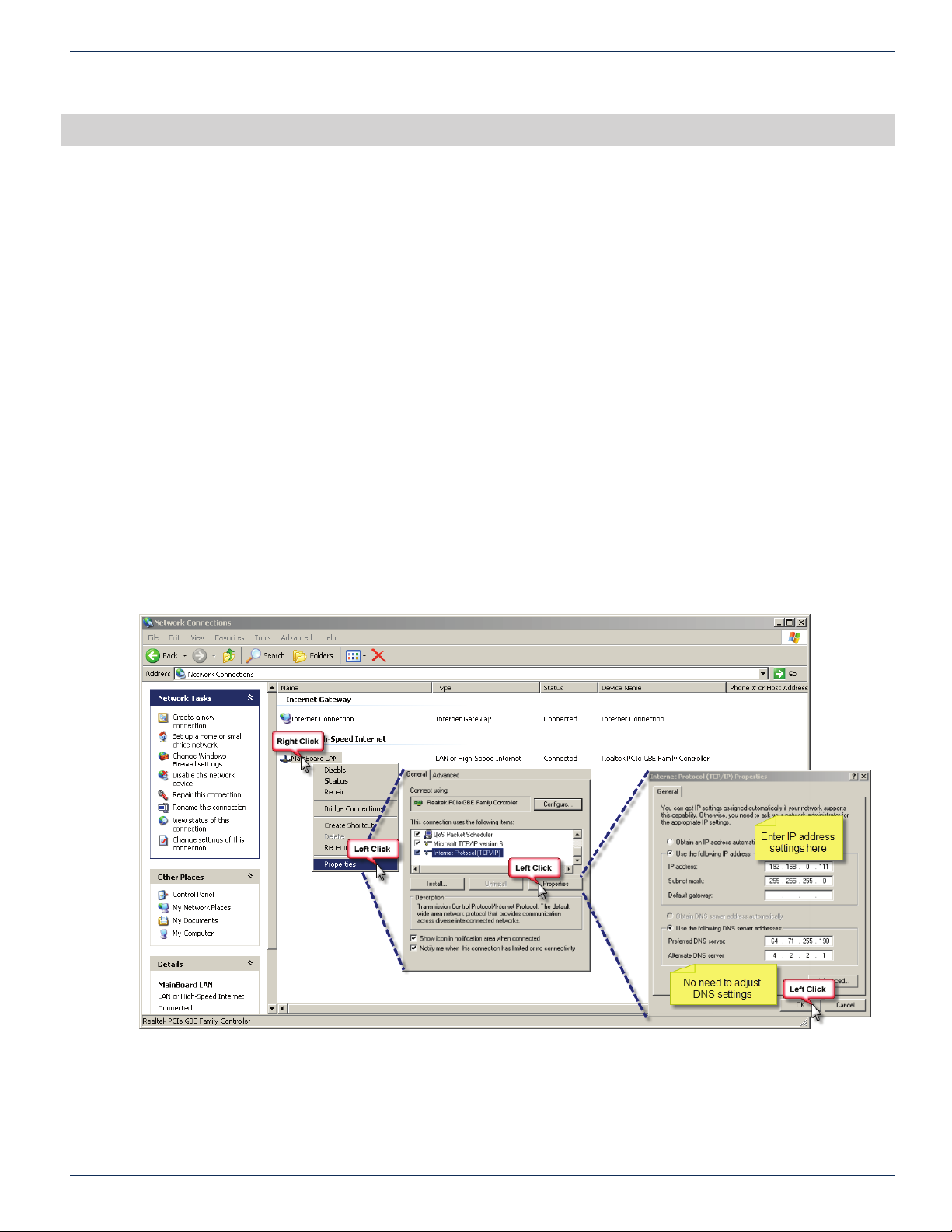
Set-up of the UCrypt unit requires a laptop or desktop PC running Microsoft® Windows or other operating system with an
available Ethernet network port and web browser software(called the “Management Computer” in the following procedures)
The Management Computer network port must be assigned an IP address in the same subnet as the UCrypt device for access
to the UCrypt Management Interface. The following procedures are for Microsoft Windows XP and a factory default IP address
setting on the UCrypt of 192.168.0.23 subnet 255.255.255.0
• Connect the Management Computer’s Ethernet adapter to the UCrypt device’s Ethernet port using a Cat5e network
cable (supplied with the unit). Link lights should illuminate indicating that the cable connection is correct and working.
• Set the Management Computer’s Ethernet interface to a static IP address on the 192.168.0.x subnet, as described
below:
◦ From the Control Panel, open Network Connections and select the connection associated with the
Ethernet adapter to be used for connecting to the UCrypt device (e.g., Local Area Connection).
or other OS
CHAPTER 7: MANAGEMENT INTERFACE
◦ Right click on the connection and select Properties.
◦ Select Internet Protocol (TCP/IP) and click Properties.
◦ Click the selection box beside Use the following IP address to enter a check mark in the box.
◦ In the IP address eld, enter 192.168.0.x (where x represents any number from 1-253 except 23).
◦ In the Subnet mask eld enter 255.255.255.0.
◦ Click OK and then OK again in the previous window.
MDU Solutions® – UCrypt® IP to IP – Quick Start Guide 7-1
Page 18
CHAPTER 7: MANAGEMENT INTERFACE
7.3 Log in to the Management Interface
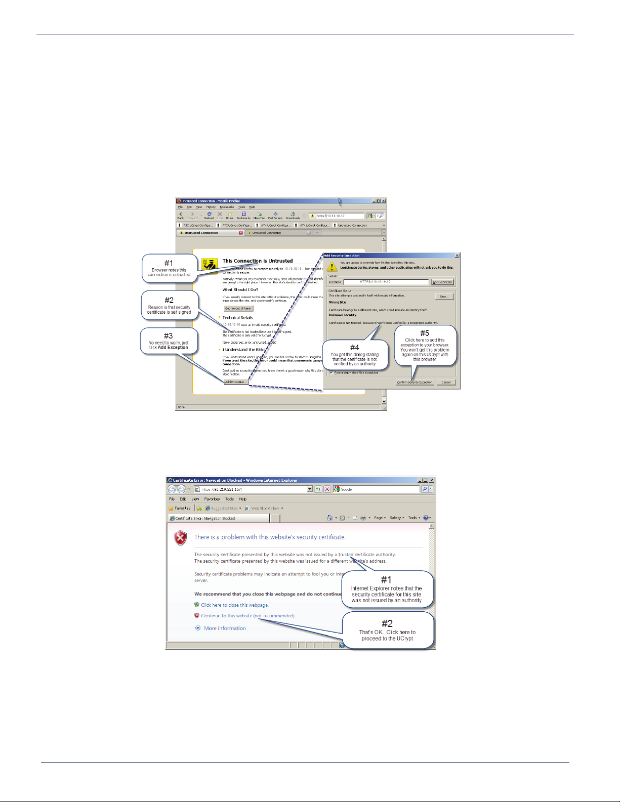
On the management computer, open a web browser and enter https://192.168.0.23 in the address eld.
If this is the rst time you have connected to this UCrypt device with this Management Computer, you may get a warning of a
security violation or error. This is due to the UCrypt device having a self signed security certicate and is not a security threat
but your browser identies it as such. Simply accept the security exception and proceed to the login screen as shown next.
Other browsers will typically respond in the same manner.
Warning For Firefox Browser
Warning For Internet Explorer
Warning in Firefox
Warning in Internet Explorer
7-2 MDU Solutions® – UCrypt® IP to IP – Quick Start Guide
Page 19
CHAPTER 7: MANAGEMENT INTERFACE
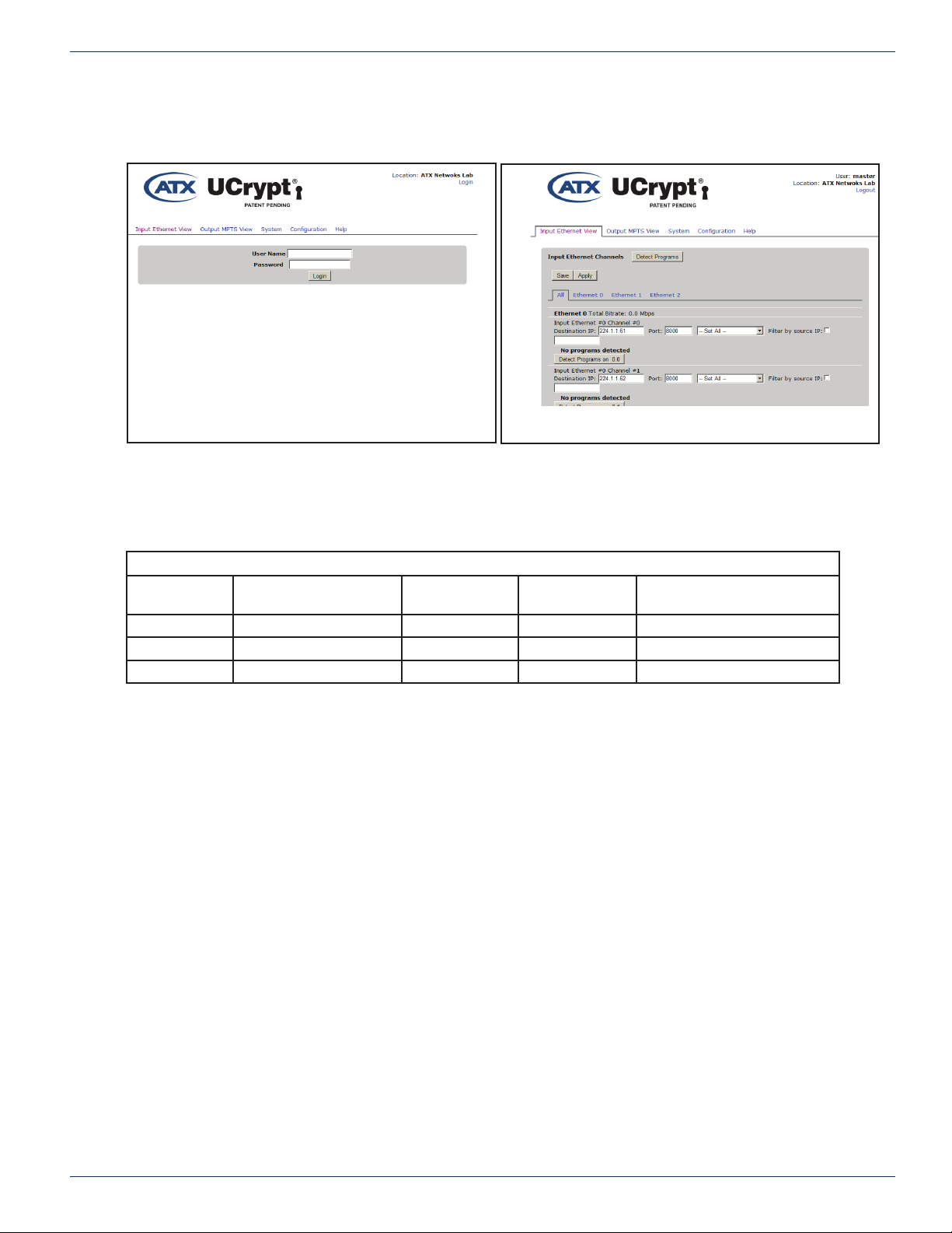
After navigating the security warnings, you should be presented with the following screen, on the left, displaying the login
window:
Login Window
Logged In
Enter the appropriate User Name and Password for the access level you require from the table below.
Default User Names, Passwords and Privileges
Account User Modify UCrypt®
Settings
master Yes Yes Yes atx_ucrypt_master_password
admin Yes No No atx_ucrypt_admin_password
user No No No atx_ucrypt_user_password
When the login username and password are successfully entered, the screen on the right above will be presented.
Install Updates Set Passwords Default Password
MDU Solutions® – UCrypt® IP to IP – Quick Start Guide 7-3
Page 20

CHAPTER 7: MANAGEMENT INTERFACE
This page intentionally left blank
7-4 MDU Solutions® – UCrypt® IP to IP – Quick Start Guide
Page 21
CHAPTER 8: INPUT ETHERNET VIEW TAB - CONFIGURATION
8. INPUT ETHERNET VIEW TAB - CONFIGURATION
De ne input multicasts and select programs from the transport streams for processing on the Input Ethernet View tab.
Input Ethernet View Tab
NOTE: Clicking the Apply button will cause a service interruption while the UCrypt device re-
provisions itself with the new working confi guration. It is best to make all changes necessary on all
confi guration pages and apply the changes when completed.
MDU Solutions® – UCrypt® IP to IP – Quick Start Guide 8-1
Page 22

CHAPTER 8: INPUT ETHERNET VIEW TAB - CONFIGURATION
This page intentionally left blank
8-2 MDU Solutions® – UCrypt® IP to IP – Quick Start Guide
Page 23
CHAPTER 9: OUTPUT MPTS VIEW TAB - CONFIGURATION
9. OUTPUT MPTS VIEW TAB - CONFIGURATION
Con gure output programs and multiplexes on the Output MPTS tab.
Output MPTS View Tab
NOTE: Clicking the Apply button will cause a service interruption while the UCrypt device re-
provisions itself with the new working confi guration. It is best to make all changes necessary on all
confi guration pages and apply the changes when completed.
For detailed information on con guration of this page, go to the ATX website (atxnetworks.com) in the Resources & Support
section, User Documents sub-section to download the Installation & Operation Manual.
MDU Solutions® – UCrypt® IP to IP – Quick Start Guide 9-1
Page 24

CHAPTER 9: OUTPUT MPTS VIEW TAB - CONFIGURATION
This page intentionally left blank
9-2 MDU Solutions® – UCrypt® IP to IP – Quick Start Guide
Page 25
10. SYSTEM TAB - CONFIGURATION
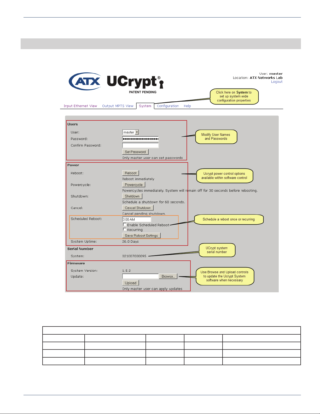
Access system con guration properties on the System tab.
CHAPTER 10: SYSTEM TAB - CONFIGURATION
System Tab - Part 1
10.1 Default User Names and Passwords
Default User Names, Passwords and Privileges
Account User Modify UCrypt® Settings Install Updates Set Passwords Default Password
master Yes Yes Yes atx_ucrypt_master_password
admin Yes No No atx_ucrypt_admin_password
user No No No atx_ucrypt_user_password
For detailed information on con guration of this page, go to the ATX website (atxnetworks.com) in the Resources & Support
section, User Documents sub-section to download the Installation & Operation Manual.
MDU Solutions® – UCrypt® IP to IP – Quick Start Guide 10-1
Page 26
CHAPTER 10: SYSTEM TAB - CONFIGURATION
System Tab - Part 2
For detailed information on con guration of this page, go to the ATX website (atxnetworks.com) in the Resources & Support
section, User Documents sub-section to download the Installation & Operation Manual.
10-2 MDU Solutions® – UCrypt® IP to IP – Quick Start Guide
Page 27
CHAPTER 11: CONFIGURATION TAB - CONFIGURATION
11. CONFIGURATION TAB - CONFIGURATION
Access mass deployment and backup le utilities on the Con guration tab.
NOTE: Clicking the Apply button will cause a service interruption while the UCrypt device re-
provisions itself with the new working confi guration. It is best to make and save all changes
necessary on all confi guration pages, then apply the changes when completed.
For detailed information on con guration of this page, go to the ATX website (atxnetworks.com) in the Resources & Support
section, User Documents sub-section to download the Installation & Operation Manual.
MDU Solutions® – UCrypt® IP to IP – Quick Start Guide 11-1
Page 28

CHAPTER 11: CONFIGURATION TAB - CONFIGURATION
This page intentionally left blank
11-2 MDU Solutions® – UCrypt® IP to IP – Quick Start Guide
Page 29

12. SERVICE & SUPPORT
12.1 Contact ATX Networks
Please contact ATX Technical Support for assistance with any ATX products. Please contact ATX Customer Service to
obtain a valid RMA number for any ATX products that require service and are in or out-of-warranty before returning a failed
module to the factory.
Digital Video Products
(DVIS, DigiVu, UCrypt, VersAtivePro)
TECHNICAL SUPPORT
Tel: (905) 428-6068 – press *3 then press 1
Toll Free: (800) 565-7488 – press *3 then press 1 (USA & Canada only)
Email: [email protected]
CUSTOMER SERVICE
ATX Networks
1-501 Clements Road West
Ajax, ON L1S 7H4 Canada
CHAPTER 12: SERVICE & SUPPORT
Tel: (905) 428-6068 – press *1
Toll Free: (800) 565-7488 – press *1 (USA & Canada only)
Fax: (905) 427-1964
Toll Free Fax: (866) 427-1964 (USA & Canada only)
12.2 Warranty Information
All of ATX Networks’ products have a 1-year warranty that covers manufacturer’s defects or failures.
MDU Solutions® – UCrypt® IP to IP – Quick Start Guide 12-1
Page 30

ISO
REGISTERED
9001:15
© 2018 ATX Networks
Printed in Canada
Information in this document is subject to change without notice.
Rev. 06/18 (ANW0955)
ATX Networks
1-501 Clements Road West, Ajax, ON L1S 7H4 Canada
Tel: 905.428.6068 | Toll Free: 800.565.7488 | [email protected]
www.atxnetworks.com
 Loading...