

Page 1

KT133TX / KT133BX
AMD Socket A
Duron
TM
/ Athlon
TM
ATX MAINBOARD
( VER. 1.x )
USER’S MANUAL
DOC NUMBER: UM-KT133TX-E1 .....................................................................PRINTED IN TAIWAN
Page 2

VIA KT133 ATX MAINBOARD TABLE OF CONTENTS
i
TABLE OF CONTENTS
Chapter & Section Page
1. INTRODUCTION ............................................................................................. 1-1
1.1 OVERVIEW ........................................................................................... 1-1
1.2 MAINBOARD LAYOUT ..................................................................... 1-3
1.3 SPECIFICATIONS ................................................................................ 1-4
2. INSTALLATION .............................................................................................. 2-1
2.1 UNPACKING ......................................................................................... 2-1
2.2 QUICK INSTALLATION..................................................................... 2-3
2.3 HOW TO POWER ON THE PC SYSTEM ........................................ 2-4
2.4 POWER OFF THE PC SYSTEM......................................................... 2-6
3. HARDWARE SETUP ...................................................................................... 3-1
3.1 INSTALLATION OF CPU ................................................................... 3-1
3.2 INSTALL THE DRAM MODULES ................................................. 3-3
3.3 CONNECTORS...................................................................................... 3-5
3.3.1 PCI SLOT.................................................................................. 3-5
3.3.2 AGP SLOT ................................................................................ 3-6
3.3.3 AMR SLOT ............................................................................... 3-6
3.3.4 ISA SLOT.................................................................................. 3-7
3.3.5 BAT1: BATTERY SOCKET .................................................. 3-7
3.3.6 CN1/CN2: PS/2 MOUSE AND KEYBOARD........................ 3-8
3.3.7 CN3 : SERIAL PORT COM 1 CONNECTOR ..................... 3-8
3.3.8 CN4 : SERIAL PORT COM 2 CONNECTOR ..................... 3-8
3.3.9 CN5: PARALLEL PORT CONNECTOR .......................... 3-9
3.3.10 CN6: USB 1 .............................................................................. 3-9
3.3.11 CN7: USB 2 ............................................................................... 3-9
3.3.12 CN8: FLOPPY DISK CONNECTOR .................................... 3-10
3.3.13 CN9 : IDE 1 CONNECTOR.................................................... 3-10
3.3.14 CN10: IDE 2 CONNECTOR .................................................. 3-10
3.3.15 CN12: IR CONNECTOR......................................................... 3-11
3.3.16 CN13: COOLING FAN 1 POWER CONNECTOR ............. 3-11
3.3.17 CN15: ATX POWER CONNECTOR .................................. 3-12
3.3.18 CN16: WOL (WAKE ON LAN) CONNECTOR .................. 3-12
3.3.19 CN17: COOLING FAN 2 POWER CONNECTOR ............ 3-13
3.3.20 CN18: AUDIO/GAME CONNECTOR .................................. 3-13
3.3.21 CN21 / CN22: CD-IN CONNECTOR .................................... 3-14
3.3.22 CN30: USB 3 CONNECTOR .................................................. 3-16
Page 3

VIA KT133 ATX MAINBOARD
ii
3.3.23 CN31: USB 4 CONNECTOR .................................................. 3-16
3.3.24 PUSH BUTTONS AND LED CONNECTORS ..................... 3-17
3.3.25 SPEAKER AND POWER LED CONNECTOR:.................. 3-19
3.4 JUMPERS ............................................................................................... 3-20
3.5 INSTALLATION OF DEVICE DRIVERS ......................................... 3-23
4. AWARD BIOS SETUP ................................................................................... 4-1
4.1 GETTING STARTED .......................................................................... 4-1
4.2 MAIN MENU......................................................................................... 4-2
4.3 CONTROL KEYS................................................................................. 4-3
4.4 STANDARD CMOS SETUP............................................................... 4-4
4.5 ADVANCED BIOS FEATURES ........................................................ 4-6
4.6 ADVANCED CHIPSET FEATURES ................................................ 4-9
4.7 INTEGRATED PERIPHERALS ........................................................ 4-13
4.8 POWER MANAGEMENT SETUP...................................................... 4-16
4.9 PNP/PCI CONFIGURATION ............................................................. 4-21
4.10 PC HEALTH STATUS........................................................................ 4-23
4.11 FREQUENCY/VOLTAGE CONTROL .............................................. 4-24
4.12 LOAD OPTIMIZED DEFAULTS...................................................... 4-25
4.13 SET SUPERVISOR PASSWORD...................................................... 4-26
4.14 SET USER PASSWORD ..................................................................... 4-27
4.15 SAVE & EXIT SETUP / EXIT WITHOUT SAVING ....................... 4-29
5. HOW TO UPDATE THE SYSTEM BIOS..................................................... 5-1
IMPORTANT
AMD Duron™ and Athlon™ processors require special care
on the CPU cooling fan. Before you can make sure that the
proper cooling fan is installed on the CPU correctly, Please
do not power on the PC system. Otherwise, the CPU will be
destroyed because of the high temperature.
Page 4

VIA KT133 ATX MAINBOARD
iii
SOMETHING IMPORTANT !
¶ TRADEMARKS
All trademarks used in this manual are the property of their respective owners.
¶ LOAD SETUP DEFAULTS
“LOAD OPTIMIZED DEFAULTS” is the function which will have the BIOS default
settings loaded into the CMOS memory, these default settings are the best-case
values which will optimize system performance and increase system stability This
function will be necessitated when you receive this mainboard, or when the system
CMOS data is corrupted. Please refer to the Section 4.12 for the procedures.
¶ DISCHARAGE CMOS DATA
Whenever you want to discharge the CMOS data or open the system chassis, Make
sure to disconnect the AC power first because there is always the 5V standby voltage
connected to the ATX form-factor mainboard. Without disconnecting the AC power
connector from the PC system, the mainboard can be damaged by any improper
action .
¶ WAKE ON LAN
In order to support the Wake On LAN feature, the system requires a special SPS
(Switching Power Supply), Such power supply must be able to provide at least 700
mA of driving capability on the “5V standby” voltage. Please refer to the Section 3.3
for pin assignment.
¶ WARNING !
The "Static Electricity" may cause damage to the components on the mainboard, In
order to avoid the damage to the mainboard accidentally, please discharge all static
electricity from your body before touching this mainboard.
¶ NOTICE
Information presented in this manual has been carefully checked for reliability;
however, no responsibility is assumed for inaccuracies. The information contained in
this manual is subject to change without notice.
Page 5

VIA KT133 ATX MAINBOARD INTRODUCTION
1-1
1. INTRODUCTION
1.1 OVERVIEW
This Mainboard is the ATX form-factor with the Socket A CPU connector
designed on the board. VIA KT133 chipset is chosen as the system core logic of
the mainboard for the AMD Duron
TM
and Athlon
TM
processors. Basically,
Duron
TM
and Athlon
TM
are the seventh-generation micro-architecture (K7)
developed by AMD. Such processors are powerful enough to support wide range
of application for various purposes. Please refer to the following for the brief
specification of the Socket A processors:
¥ Socket A ( 462 pin PGA packing).
¥ Built-in L1 and L2 cache.
¥ Superscalar floating point unit with AMD enhanced 3Dnow!
TM
technology.
¥ 200MHz high speed front side system bus interface.
VT82C686A (or VT82C686B) is chosen as the southern bridge of the core logic
on the mainboard. It is a high integration, power-efficient and high compatibility
device. It supports the PCI bridge functionality to make a complete PC99compliant PCI/ISA system. Beside the ISA extension bus functionality, there are
two channels of "PIO” and "Ultra DMA Bus Master” IDE ports to support the
most updated Ultra DMA HDD. There are one Floppy Disk controller, two high
speed Serial ports (UARTs), one multi-mode Parallel port, one PS/2™ mouse
port, one IR interface and four USB ports designed on the board for wide variety
of peripheral connection.
What is Socket A?
Basically, Socket A is the CPU connector designed for the socket type of
AMD K7
processors. There is the L2 cache memory built inside the Socket
A processor to give the most outstanding performance and reliability The
AMD K7 processor is an innovative processor designed for the value PC
market. With the AMD K7 processor, computer users will get a PC capable
of running today's applications with ease, and with enough power to run the
applications of tomorrow
Page 6
VIA KT133 ATX MAINBOARD INTRODUCTION
1-2
Accelerated Graphic Port (AGP)
There is the AGP slot built on the board where you can install the AGP VGA
card. Basically, the demand for 3D graphic rendering and the throughput of
screen display is increasing. AGP is such a new interface which will increase
massive bandwidth between VGA card and CPU to increase the display
quality and performance. There is the full featured AGP slot designed on the
mainboard which supports the 4X AGP mode. When you have the 4X AGP
display card installed on the mainboard, it will enhance the system display
performance tremendously.
Hardware Monitoring
There is the hardware monitoring designed on the mainboard. You can
always use the hardware monitoring feature to monitor the system healthy
status. Basically, the hardware monitoring feature will monitor the status of
the cooling fan speed, CPU voltage and system temperature etc.
There is also the 3D audio interface designed on the mainboard. When the audio
interface is installed on the mainboard, you need not to invest any on the audio
interface card. Simply have the speaker connected to the audio connector (CN18)
on the mainboard and you will have the 3D sound effect in your PC system.
According to different logic applied on this mainboard, several different model
will be created as shown in the following table: Please refer to the following table
for the difference:
MODEL NAME IDE Interface AMR Slot Onboard 3D Audio
KT133TX Ultra DMA 33/66 Yes Yes
KT133TXL Ultra DMA 33/66 No No
KT133BX Ultra DMA 33/66/100 Yes Yes
KT133BXL Ultra DMA 33/66/100 No No
Page 7

VIA KT133 ATX MAINBOARD INTRODUCTION
1-3
1.2 MAINBOARD LAYOUT
U
S
B
D
I
M
M
3
A
G
P
S
L
O
T
CPU
C
N
9
I
D
E
1
C
N
1
0
I
D
E
2
D
I
M
M
2
D
I
M
M
1
BAT1
123
C
N
8
F
D
C
4
B
A
C
JP1
P
C
I
S
L
O
T
CN17
CN12
IR
CD-IN
Panel
Button
Chassis
Fan
A
M
R
CPU
Fan
ATX-Power
Connector
A= COM1
B=COM2
C=LPT
CN16
WOL
1= SPK-OUT
2=LINE-IN
3=MIC-IN
4=MIDI/GAME
USB3
USB4
SPK
PWR-LED
JP8
Mouse
K/B
USB1
USB2
Sleep
LED
P
C
I
S
L
O
T
P
C
I
S
L
O
T
P
C
I
S
L
O
T
P
C
I
S
L
O
T
CN34
PS/2
Mouse
USB2
USB1
COM1 Audio Port
Parallel Port
K/B
Game/MIDI
Port
COM 2
Note:
Audio port (CN18) and
AMR slot are the
optional choices on the
mainboard.
Page 8

VIA KT133 ATX MAINBOARD INTRODUCTION
1-4
1.3 SPECIFICATIONS
¥ CPU
AMD Duron
TM
and Athlon
TM
Socket A processors
¥ CPU VCC
Switching Voltage Regulator circuits on board, supports +1.10V DC through
+1.85V DC CPU Core Voltage.
Note : The CPU Core Voltage will be Detected and adjusted automatically by the
this mainboard, so there is no manual-adjustment required to select the CPU
voltage. Simply plug in the CPU and start immediately.
¥ WORD SIZE
Data Path : 8-bit, 16-bit, 32-bit, 64-bit
Address Path : 32-bit
¥ PC SYSTEM CHIPSET
VIA VT8363 and VT82C686A (or VT82C686B) chipset
¥ FRONT SIDE BUS FREQUENCY
200MHz. [100MHz DDR (Double Data Rate)]
¥ MEMORY
Three 168-pin DIMM sockets are designed onboard. Supports PC-100, PC-133 and
VCM SDRAM (Virtual Channel Memory). Maximum memory size up to 1.5GB
¥ BIOS
AWARD System BIOS. 2M bit Flash ROM
(Supports Plug & Play, ACPI, DMI and Green functions).
¥ EXPANSION SLOTS
AGP Slot : One 32-bit AGP Slot (Supports 1x, 2x and 4X AGP graphics cards)
PCI Slot : Five 32bit PCI slots.
ISA Slot : One 16-bit ISA slot (the ISA slot is PCI/ISA shared)
AMR Slot : One AMR slot for audio and modem interface card.
(Note: KT133TXL and KT133BXL do not have AMR slot on the mainboard.)
¥ WOL PORTS
One WOL connector supports Wake-On-LAN functionality.
Page 9

VIA KT133 ATX MAINBOARD INTRODUCTION
1-5
¥ USB PORTS
Four Universal Serial Bus (USB) ports..
¥ IDE PORTS
Two channels of Ultra DMA33/66 Bus Master IDE ports (when VT82C686B is
installed on the board, it supports Ultra DMA /100).
¥ SUPER I/O PORTS
1. Two high speed NS16C550 compatible serial ports (UARTs).
2. One parallel port, supports SPP/EPP/ECP mode.
3. One Floppy Disk Control port.
¥ IR PORT
One HPSIR and ASKIR compatible IR transmission connector (5-pin).
¥ MOUSE AND KEYBOARD
One PS/2™ mouse connector, One PS/2™ keyboard connector.
¥ 3D SOUND (Optional)
Integrated PCI-mastering dual full-duplex direct-sound AC97-link-compatible
sound interface. (Note: KT133TXL and KT133BXL do not have the 3D audio
interface on the mainboard.)
¥ HARDWARE MONITORING
The hardware monitoring feature is designed on the board to monitor hardware
healthy status like system voltage, system temperature, and cooling fans. When the
hardware monitoring program is installed in the PC system, it will keep monitoring
the mainboard status. If there is something wrong, then you will receive a warning
message on the screen display so that you can take proper action to prevent your
system from damage.
There is the hardware monitoring program in the CD which comes with this
mainboard. If you feel like to use the hardware monitoring feature to monitor the
mainboard healthy status, please refer to the following for the procedure:
1. Insert the CD disc into the CD ROM drive.
2. Change the directory to "D:\Driver\Mainboard\VIA\Hardware Monitoring"
3. Click on the "SETUP" icon and follow the screen instruction to complete the
setup.
Page 10

VIA KT133 ATX MAINBOARD INTRODUCTION
1-6
¥ ACPI
Advanced Configuration and Power Interface (ACPI) function is strongly
recommended by PC’98 because it will let you have many additional features and
that will make your PC system becomes very friendly and convenient. Followings
are the ACPI features designed on the board:
1. On Now: power on the system by panel-switch, Modem ring-in, RTC
alarm or LAN signal.
2. Power off (soft-off) by OS or Panel-switch.
3. Resuming of PC system. (such as Modem ring-in, RTC alarm, .... etc.)
4. Supports Full-On/Doze/Standby/Suspend operating modes.
¥ DIMENSION
1. Width & Length : 305 mm x 210 mm.
2. Height : 1 1/2 inches.
3. PCB Thickness : 4 layers, 0.05 inches normal.
4. Weight : 18 ounces.
¥ ENVIRONMENT LIMITATION
1. Operating Temperature : 10 to 40 . (50 to 104 )
2. Required Airflow : 50 linear feet per minute across CPU.
3. Storage Temperature : - 40 to 70. (- 40 to 158)
4. Humidity : 0 to 90% non-condensing.
5. Altitude : 0 to 10,000 feet.
Page 11

VIA KT133 ATX MAINBOARD INSTALLATION
2-1
2. INSTALLATION
2.1 UNPACKING
The mainboard contains the following components. Please inspect the following
contents and confirm that everything is there in the package. If anything is missing or
damaged, call your supplier for instructions before proceeding.
2222
Mainboard
2222
User‘s manual
2222
One IDE cable
2222
One FDD cable
USB Cable (Optional)
2222
One CD diskette for device driver and utility programs
Note: there is the Virtual Drive and Stop Virus included in the CD, they are the
most powerful and valuable software tools for your daily work. Please refer
to the CD for detail function description.
The color box of the mainboard can protect the mainboard from unexpected damage
during the transportation. Since this mainboard contains electrostatic sensitive
components and it can be easily damaged by static electricity. So the mainboard is
sealed inside a ESD bag so that the mainboard can be protected against the unexpected
damage. Please leave always leave the mainboard sealed in the original packing until
when installing.
A grounded anti-static mat is recommended when unpacking and installation. Please
also attached an anti static wristband to your wrist and have it grounded to the same
point as the anti-static mat.
Page 12
VIA KT133 ATX MAINBOARD INSTALLATION
2-2
When you have opened the color box of the mainboard, please observe the mainboard
carefully to make sure there is no shipping and handling damage before you can start to
install the PC system.
Having finished all the procedures above, you are now ready to install the mainboard to
the chassis. Please make sure that the chassis is the ATX type so that the mounting hole
will match with this mainboard.
IMPORTANT NOTICE:
The standby voltage is always active. Whenever you are
installing any component on the mainboard.
- BE SURE TO DISCONNECT THE POWER CABLE.
*** IMPORTANT ***
AMD Duron™ and Athlon™ processors require special
care on the CPU cooling fan. Before you can make sure
that the proper cooling fan is installed on the CPU
correctly, lease do not power on the PC system. Otherwise,
the CPU will be destroyed because of the high
temperature.
Page 13

VIA KT133 ATX MAINBOARD INSTALLATION
2-3
2.2 QUICK INSTALLATION
This section provides a quick installation guide. If you do not have enough
experience to install the mainboard the PC system correctly, please refer to the
following procedures to install your PC system:
1. Refer to Section 2-1 to avoid the static electricity damage.
2. Remove the mainboard from the packing and put it on the table. (the surface must be
very smooth)
3. Lift the actuation level of the CPU socket and then refer to the CPU user’s guide to
install the CPU onto the socket properly. (refer to Section 3-1 to find CPU socket)
4. When the CPU is installed on the socket, close the socket by lowering and locking
the actuation lever.
5. Have the CPU cooling fan installed onto the CPU and connect it to the cooling fan
power connector.
6. Install the DIMM module onto the DIMM socket. (refer to Section 3-2)
7. Install the mainboard into the cabinet. (please do not connect the power cable!!).
8. Connect the panel switch and LED to the mainboard. (refer to Section 3-3)
9. Use the ribbon cable to connect the FDD, IDE HDD and CD ROM drive.
10. Install the VGA card, LAN card and FAX/Modem card …etc.
11. Have the power supply connected to the ATX power connector on the mainboard.
12. Connect the peripheral devices such as monitor, keyboard, mouse … etc.
13. Connect the power cable and power on the PC system.
14. When you see the POST screen display (refer to Section 4-1), click the “Del” key to
trigger the BIOS setup screen.
15. Select “Load Optimized Default” in the BIOS setup program so that the suggested
parameter will be loaded into the CMOS memory.
16. Exit the BIOS setup program and then restart the PC system.
17. Install the operation system (such as Windows).
18. Install the device drivers and other application software.
IMPORTANT NOTICE:
1. Never power on the PC system unless a qualified cooling fan is installed properly.
2. Before all the components are installed in the PC system properly, please do not
connect the power cable to the PC system.
3. Do not install mainboard into the cabinet and then install DIMM module and CPU.
Otherwise, this mainboard may be damaged when install CPU and DIMM module.
Page 14

VIA KT133 ATX MAINBOARD INSTALLATION
2-4
2.3 HOW TO POWER ON THE PC SYSTEM
When the mainboard has been installed successfully, there are several ways to
power on the system. Please read the following description for all the details.
¨ POWER BUTTON
The power button can be programmed by COMS setup program and it has different
features. Please refer to page 3-16 for detail function description.
¨ RTC ALARM
PC system can be started up by the RTC setting in the CMOS. You can set the
alarming date and time in the RTC memory, When RTC alarms, the PC system will
be triggered and waked up automatically on the date and time which you selected in
the BIOS setup program.
Enable the "RTC Alarm Resume” selection in the BIOS setup utility, and then you
will see the input request for the date and time. (the " RTC Alarm Resume” is
located in the "POWER MANAGEMENT SETUP”, please refer to Section 4.8),
When you have stored the RTC alarm setting, the PC system will be turned on
automatically according to the date and time which is recorded in the CMOS
memory.
¨ MODEM RING-IN
The PC system can be used as a fax machine to send or receive fax messages. But
most people still use fax machine to receive their messages because it is not
practical to have the system powered on all day long waiting for the incoming
messages. Now the problem can be solved because this mainboard can be triggered
by a modem ring-in signal.
When you have a external modem installed, you can leave the PC system power
off. Whenever there is the incoming message, the PC system will be triggered by
the ring-in signal and wake up automatically to receive the message for you. From
now on, you can tell your PC system to receive the fax message for you.
Page 15

VIA KT133 ATX MAINBOARD INSTALLATION
2-5
In order to use the ring-in signal to wake up your PC system, you will have to use
the EXTERNAL MODEM and have it connected to one of the SERIAL PORTS
( COM1 or COM2 ) on the mainboard. When the mainboard detects the ring-in
signal from the serial port, the PC system will be powered on and start to receive the
incoming messages automatically..
To enable the Modem Ring-In feature, you have to run the BIOS setup utility and
enable the "Wake Up On LAN/Ring” option (it is located in the "POWER
MANAGEMENT SETUP”, please refer to Section 4.8 for the settings).
Note: This function is not available when using the internal MODEM card.
¨ WAKE ON LAN ( WOL )
There is a WOL connector CN16 on the mainboard which is designed to connect to
the signal from a LAN card which supports the Wake On LAN feature. When such
LAN card is installed, you may turn on the PC system from the remote server and
monitor the PC status. To enable this feature, you will have to use the BIOS setup
utility to enable the " Wake Up On LAN/Ring” in the BIOS setup program.
Page 16
VIA KT133 ATX MAINBOARD INSTALLATION
2-6
2.4 POWER OFF THE PC SYSTEM
There are two ways to power off the system. They are “Shut Down by Power Button”
and “ Shut Down by OS”. (such as Windows® 95 and Windows® 98, you can choose
the Shut Down from the file menu and the system will be powered off immediately ).
IMPORTANT NOTICE:
“Shut down by O/S” is always recommended because “Shut Down by Power
Button” under Windows operation may cause data lost of wrong
configuration problem. Unless your system hangs and you can not use the
“Shut down by O/S” to power off the PC system, please do not use the power
button on the front panel to power off the PC system.
Page 17
VIA 82C694 ATX Mainboard HARDWARE SETUP
3-1
3. HARDWARE SETUP
Before you can start to install this mainboard, some hardware setting is required.
To configure the mainboard is a simple task, only a few jumpers, connectors,
cables and sockets need to be selected and configured. This section will show all
the connectors and jumpers on the mainboard.
IMPORTANT
There is always the standby voltage active on the mainboard.
Be sure to remove the power cable from the PC system
when installing CPU or any other components onto the mainboard .
3.1 INSTALLATION OF CPU
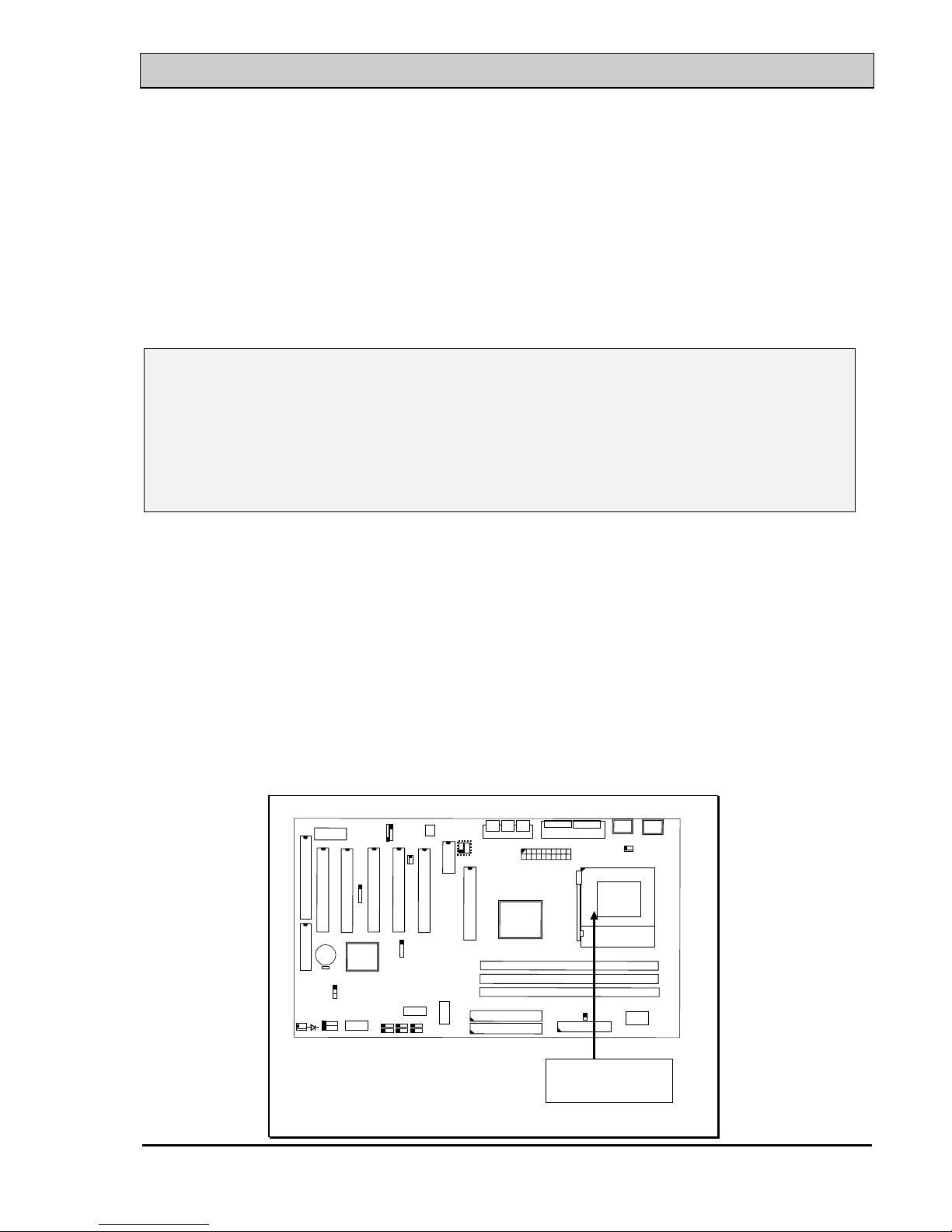
The connector on this mainboard where we can install the CPU is the “socket A”
connector as shown in the following picture. The front side system bus speed of
this mainboard will support up to 200 MHz amazing high speed. So you may feel
free to install the most updated AMD Duron™ or Athlon™ processor onto this
mainboard.
U
S
B
D
I
M
M
3
A
G
P
S
L
O
T
CPU
C
N
9
I
D
E
1
C
N
1
0
I
D
E
2
D
I
M
M
2
D
I
M
M
1
123
C
N
8
F
D
C
4
A
B
C
P
C
I
S
L
O
T
A
M
R
JP8
P
C
I
S
L
O
T
P
C
I
S
L
O
T
P
C
I
S
L
O
T
P
C
I
S
L
O
T
SOCKET A
Page 18
VIA KT133 ATX MAINBOARD HARDWARE SETUP
3-2
IMPORTANT IMPORTANT IMPORTANT IMPORTANT
AMD Duron™ and Athlon™ are the very high performance processors.
However, you will easily find that the temperature measured on the
surface of the CPU is cooking hot. So the thermal management becomes
extremely important when installing AMD Duron™ and Athlon™
processors. If the CPU cooling fan is not attached to the CPU properly,
fatal damage may occur to the CPU.
According to the document from AMD, Duron™ and Athlon™ processors
require the larger heatsink. The rotation speed of the cooling fan shall be
6,600 RPM or above. The thermal grease must be applied between the
heatsink and the CPU to improve the heat dissipation. Also, please make
sure that the heatsink is fastened securely on the CPU to make sure the
perfect surface contact so that the heat can be dissipated through the
cooling fan.
Please visit the following site to have more detail of the cooling fan and
the qualified suppliers:
http://www1.amd.com/products/athlon/thermals
IMPORTANT
AMD Duron™ and Athlon™ processors require special
care on the CPU cooling fan. Before you can make sure
that the proper cooling fan is installed on the CPU
correctly, lease do not power on the PC system. Otherwise,
the CPU will be destroyed because of the high
temperature.
Page 19

VIA KT133 ATX MAINBOARD HARDWARE SETUP
3-3
3.2 INSTALL THE DRAM MODULES
This mainboard has three DIMM sockets designed on the mainboard and you can
use the single-side or double-side DIMM module on the mainboard. Please refer
to the following picture to see the sockets for DIMM module:
DIMM 1
DIMM 2
DIMM 3
D
I
M
M
3
D
I
M
M
2
D
I
M
M
1
123
4
A
B
C
JP8
Picture of Memory sub-system.
Outlook of DIMM module
( Single-Side DIMM module )
( Double-Side DIMM Module )
Page 20

VIA KT133 ATX MAINBOARD HARDWARE SETUP
3-4
In order to have a better performance and reliability to your PC system, please refer to
the following suggestion to install the memory:
Installation of DIMM modules:
1. Minimum one DIMM module must be installed on the mainboard.
2. Please use 3.3V PC-100 or PC-133 un-buffered DIMM module.
3. You can use single side or double side DIMM module on this mainboard.
4. Please install the DIMM module starting from DIMM1 or DIMM2 first.
5. Maximum memory size: 1536MB
Page 21
VIA KT133 ATX MAINBOARD HARDWARE SETUP
3-5
3.3 CONNECTORS
The connectors on the mainboard are either the pin header type or D-type
connectors, they are used to connect the accessories or peripheral devices (such as
power, mouse, printer,...etc.). Followings are the connectors with its description
and the pin assignment which is designed on the mainboard.
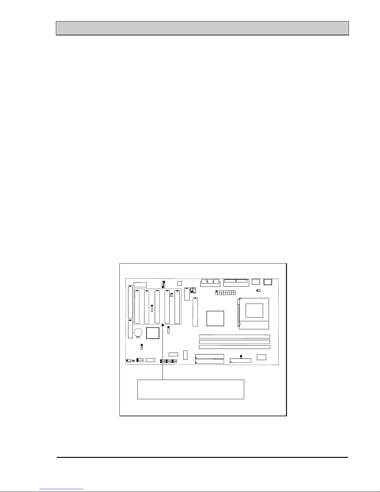
3.3.1 PCI SLOT
There are five PCI slots on the mainboard which you can install PCI add-on
cards. Please refer to the following picture to see the PC slot on the mainboard.
Five PCI slots on the board
D
I
M
M
3
D
I
M
M
2
D
I
M
M
1
123
4
A
B
C
JP8
Page 22
VIA KT133 ATX MAINBOARD HARDWARE SETUP
3-6
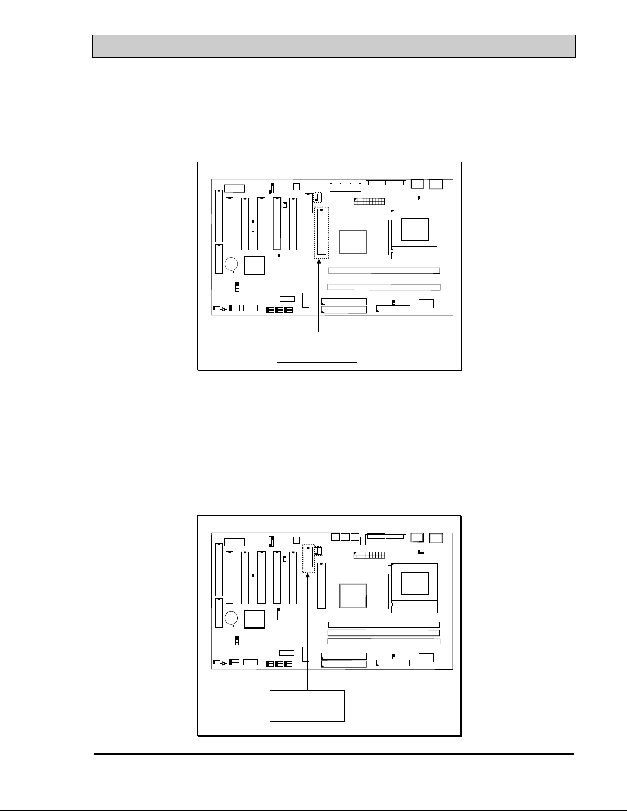
3.3.2 AGP SLOT
There is one AGP slot on the mainboard which you can install AGP VGA card.
AGP slot
D
I
M
M
3
D
I
M
M
2
D
I
M
M
1
123
4
A
B
C
JP8
3.3.3 AMR SLOT (OPTIONAL)
There is one AMR slot designed on the mainboard. You can install such AMR
modem card on the AMR slot. (Note: KT133TXL and KT133BXL do not have
AMR slot on the mainboard.)
AMR Slot
D
I
M
M
3
D
I
M
M
2
D
I
M
M
1
123
4
A B
C
JP8
Page 23

VIA KT133 ATX MAINBOARD HARDWARE SETUP
3-7
3.3.4 ISA SLOT
There is one 16-bit ISA slot designed on the mainboard which you can install
the ISA interface card.
ISA Slot
D
I
M
M
3
D
I
M
M
2
D
I
M
M
1
123
4
A
B
C
JP8
3.3.5 BAT1: BATTERY SOCKET (3 Volts Lithium battery : CR2032)
BAT1: Battery Socket
Pin# Pin name Pin# Pin name
+ Battery Positive - Ground
D
I
M
M
3
D
I
M
M
2
D
I
M
M
1
123
4
A
B
C
JP8
Page 24
VIA KT133 ATX MAINBOARD HARDWARE SETUP
3-8
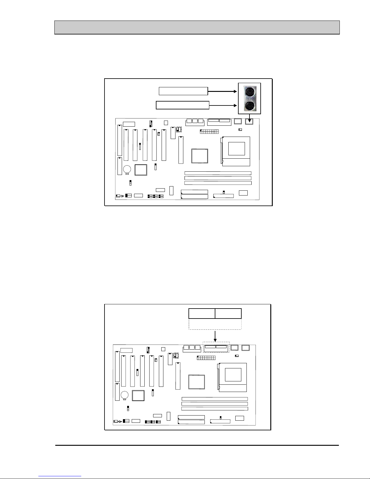
3.3.6 CN1/CN2: PS/2 MOUSE AND KEYBOARD CONNECTOR
PS/2 Mouse Connector
PS/2 Keyboard Connector
D
I
M
M
3
D
I
M
M
2
D
I
M
M
1
123
4
A
B
C
JP8
3.3.7 CN3 : SERIAL PORT COM 1 CONNECTOR
3.3.8 CN4 : SERIAL PORT COM 2 CONNECTOR
COM 2 COM 1
D
I
M
M
3
D
I
M
M
2
D
I
M
M
1
123
4
B
A
C
JP8
A = COM 1 (CN3)
B = COM 2 (CN4)
(I/O address: 3F8H/2F8H/3E8H/2E8H, IRQ3/IRQ4, selected by CMOS setup.)
Page 25

VIA KT133 ATX MAINBOARD HARDWARE SETUP
3-9
3.3.9 CN5: PARALLEL PORT CONNECTOR
(Supports SPP/EPP/ECP modes, IRQ7 or IRQ5 is selectable, ECP mode will use
either DMA 3 or DMA 1 which can be selected by the BIOS setup program)
PARALLEL PORT
D
I
M
M
3
D
I
M
M
2
D
I
M
M
1
123
4
A
B
C
JP8
3.3.10 CN6: USB 1 (UNIVERSAL SERIAL BUS) CONNECTOR
3.3.11 CN7: USB 2 (UNIVERSAL SERIAL BUS) CONNECTOR
USB 1
USB 2
D
I
M
M
3
D
I
M
M
2
D
I
M
M
1
123
4
A
B
C
JP8
Page 26

VIA KT133 ATX MAINBOARD HARDWARE SETUP
3-10
3.3.12 CN8: FLOPPY DISK CONNECTOR (IRQ6, DMA 2)
CN8: FDC Connector
D
I
M
M
3
D
I
M
M
2
D
I
M
M
1
123
4
A
B
C
JP8
3.3.13 CN9 : IDE 1 CONNECTOR (Primary IDE Port: 1F0H, IRQ 14)
3.3.14 CN10: IDE 2 CONNECTOR (Secondary IDE Port: 170H, IRQ 15)
CN10: IDE 2
CN9: IDE 1
D
I
M
M
3
D
I
M
M
2
D
I
M
M
1
123
4
A
B
C
JP8
Page 27

VIA KT133 ATX MAINBOARD HARDWARE SETUP
3-11
3.3.15 CN12: IR (INFRARED RAYS) CONNECTOR
123
4
A
B
C
JP8
1
2
3
4
5
( +5VDC )
(
NO CONNECTION )
(
IR RECEIVE )
(
GROUND )
(
IR TRANSMIT )
IR (INFRARED RAYS) CONNECTOR
3.3.16 CN13: COOLING FAN 1 POWER CONNECTOR
CN13 is the cooling fan power connector designed on the mainboard. Since it is
very close to the Socket A connector, so CN13 is recommended to connect to the
CPU cooling fan. You can see from the BIOS setup program the cooling fan
speed. When the device driver of the hardware monitoring is installed, you can
monitor the rotating speed of the CPU cooling fan in the Windows operation
system.
Page 28

VIA KT133 ATX MAINBOARD HARDWARE SETUP
3-12
123
4
A
B
C
JP8
CN13
Ground
+12V DC
Fan Sense Signal
1
2
3
1 2 3
3.3.17 CN15: ATX POWER CONNECTOR
ATX Power connector
CN15
123
4
A
B
C
JP8
3.3.18 CN16: WOL CONNECTOR (WAKE ON LAN)
In order to use the WOL LAN card to trigger the power of the PC system, the
switching power supply must be able to provide at least 700mA current driving
ability on the “5V standby” voltage.
Page 29

VIA KT133 ATX MAINBOARD HARDWARE SETUP
3-13
CN 16
WOL
1
2
3
123
4
A
B
C
JP8
3.3.19 CN17: COOLING FAN 2 POWER CONNECTOR
CN17 is the cooling fan power connector designed on the mainboard. The
location of CN17 is very close to the panel switch connector. If you have the
chassis cooling fan in your PC system, you can have it connected to CN17 to
reduce the temperature inside the PC system.
Ground
+12V DC
Fan Sense Signal
1
2
3
CN 17
1 2 3
123
4
A
B
C
JP8
3.3.20 CN18: AUDIO/GAME CONNECTOR (OPTIONAL)
Page 30

VIA KT133 ATX MAINBOARD HARDWARE SETUP
3-14
There is the 3D audio interface built on this mainboard (audio interface is optional
on the board.). Please refer to the following picture for the audio interface.
123
4
1. SPK_OUT
2. LINE_IN
3. MIC._IN
4. GAME /MIDI PORT
CN18
123
4
A
B
C
JP8
3.3.21 CN21 / CN22: CD-IN CONNECTOR (CN21 and CN22 are optional)
The CD-IN connectors on the board can be used to connect to the CD ROM
audio out. There are two different type of connectors designed on the mainboard,
please check with your CD ROM drive and decide which connector can be used
to connect to the CD ROM drive. ( these connectors is absent on KT133TXL and
KT133BXL mainboards)
CN22CN21
1 2 3 4
LG GR
1 2 3 4
LG RG
123
4
A
B
C
JP8
Page 31

VIA KT133 ATX MAINBOARD HARDWARE SETUP
3-15
L = Left channel audio-out
R = Right channel audio-out
G = Audio Ground
Page 32

VIA KT133 ATX MAINBOARD HARDWARE SETUP
3-16
3.3.22 CN30: USB 3 (UNIVERSAL SERIAL BUS) CONNECTOR
3.3.23 CN31: USB 4 (UNIVERSAL SERIAL BUS) CONNECTOR
In order to connect the USB device, you will need to have the USB cable
connected to the CN30 and CN31. Wrong USB cable may cause serious damage
to this mainboard. Please contact your local supplier for the correct USB cable.
CN30
CN31
USB 3
USB 4
123
4
A
B
C
JP8
3
2
1
4
5
3
4
5
2
1
CN30CN31
Pin assignment of USB connector:
CN 31 (USB4) CN 30 (USB3)
Pin #
Assignment Pin # Assignment
●
5 Ground (BLACK WIRE)
●
1+5V DC (RED WIRE)
●
4 Ground (BLACK WIRE)
●
2 DATA- (WHITE WIRE)
●
3 DATA+ (GREEN WIRE)
●
3 DATA+ (GREEN WIRE)
●
3 DATA- (WHITE WIRE)
●
4 Ground (BLACK WIRE)
●
1+5V DC (RED WIRE)
●
5 Ground (BLACK WIRE)
IMPORTANT:
Wrong USB cable will destroy the mainboard, please make sure to use the
correct USB cable on CN30 and CN31.
Page 33

VIA KT133 ATX MAINBOARD HARDWARE SETUP
3-17
3.3.24 PUSH BUTTONS AND LED CONNECTORS
A series of connectors are designed on the board to connect the push buttons and
LED indicators. Followings are the details:
PUSH BUTTONS AND LED CONNECTORS
RS: Reset Button connector
HL: HDD LED connector
SL: Sleep LED connector
PW: Power On / Off Suspend switch
PW SL HL RS
123
4
A
B
C
JP8
1. RS Reset Button Connector
Pin # Signal name
Pin1&2 Function
1 Reset Control Open No action
2 Ground Short System Reset
2. HL IDE HDD LED Connector
Pin # Signal name
1 + 5V DC Pull-up
2 HDD Active Signal
3. SL Sleep LED Connector
This LED will be lightened when the AC power is connected and the
system is power off, darkened when the AC power is disconnected or the
system is powered on.
Pin # Signal name
1 Signal Pin
2 Ground
Page 34

VIA KT133 ATX MAINBOARD HARDWARE SETUP
3-18
4. PW Power On / Off and External Suspend Switch Connector
According to the setup in CMOS, the PW connector has two functions. It
can be the Power Switch or Suspend Switch of your PC system.
(please refer to the Aware BIOS setup in Section 4)
If the setup in CMOS is “Delay 4 Sec.”, the function of “PW” will be:
A. When system power is "OFF":
Press this switch, the system will power on.
B. When system power is "ON" :
a. The system is in Full-ON mode :
a-1. Click on this switch ( less than 4 seconds ), the system will be
turned into Suspend mode. (turn into the GREEN mode)
a-2. Press and hold this switch for more than 4 seconds, the system
will be powered off.
b. When the system is in Suspend mode :
b-1. Click on this switch ( less than 4 seconds ), the system will
return to Full-ON mode.
b-2. Press and hold this switch more than 4 seconds, the system will
be powered off.
The setup in CMOS is “Instant-off”:
A. When system power is "OFF" :
Click on this switch, the system will be powered on.
B. When system power is "ON" :
Click on this switch, the system will be powered off instantly.
Page 35

VIA KT133 ATX MAINBOARD HARDWARE SETUP
3-19
3.3.25 SPEAKER AND POWER LED CONNECTOR
Speaker & Power LED Connectors
SPK
1 2 3 4
1 2 3 4
PWRLED
123
4
A
B
C
JP8
SPK: Speaker connector
1Pin #
Signal name
1+ 5V DC
2 No Connection
3 No Connection
4 Speaker Data Signal
5
PWRLED: Front Panel Power LED Connector
1Pin #
Signal name
1 Pullup (+ 5V DC for Power LED)
2 No Connection
3 Ground
4 No Connection
5
Page 36

VIA KT133 ATX MAINBOARD HARDWARE SETUP
3-20
3.4 JUMPERS
This section will discuss the jumper setting on the mainboard. In order to let you have
better idea of the jumper setting, please see below for the explanation of jumper
settings before you start this section.
open
1-2
1
2-3
1
1
11
short
,
,
A jumper is a set of two, three or more jumper pins which allow users to make different
system configuration by putting the plastic connector plug (mini-jumper) on it. The
jumper setting is necessary when installing different components onto the mainboard.
(A) JP9: CMOS DATA CLEAR BUTTON
Basically, the BIOS setup program will have all the setting saved in the CMOS
memory so that the system BIOS will know how to initialize the core logic of the
mainboard. In case that you made some wrong setting in the BIOS setup program
and caused the PC system failed to boot, you can use JP9 to clear all the setting
which is saved in the CMOS memory.
1-2 Short: Normal Setting.
2-3 Short: Clear CMOS.
JP9
1 2 3
123
4
A
B
C
JP8
Page 37

VIA KT133 ATX MAINBOARD HARDWARE SETUP
3-21
Followings are the procedures to use JP9 to clear the BIOS setting which is saved in the
CMOS memory.
1. Unplug the AC power cable from the PC system.
2. Open the cabinet of the PC system.
3. Put the mini jumper on pin 2-3 of JP9 around 3 to 5 seconds and then
return it to the original position ( pin 1-2 ).
4. Close the cabinet
5. Re-connect the AC power cable.
6. Power on the PC system and then run BIOS setup program to
reconfigure the PC system.
Note: Improper BIOS setting may cause hang-up to the PC system, Should it be
happened, you may use JP9 to clear the information which is stored in
the CMOS memory and get the PC system back to normal. Improper
connection may cause permanent damage to the mainboard. Please refer
to the following steps to clear the CMOS
IMPORTANT:
After you have use JP9 and clear the setting which is saved in the CMOS
memory, we suggest that you use “Load Optimized Defaults” and have the
optimized parameters loaded into the BIOS setup program. Such
parameters were fine tuned and they will let you have the optimized
performance and stability.
Page 38
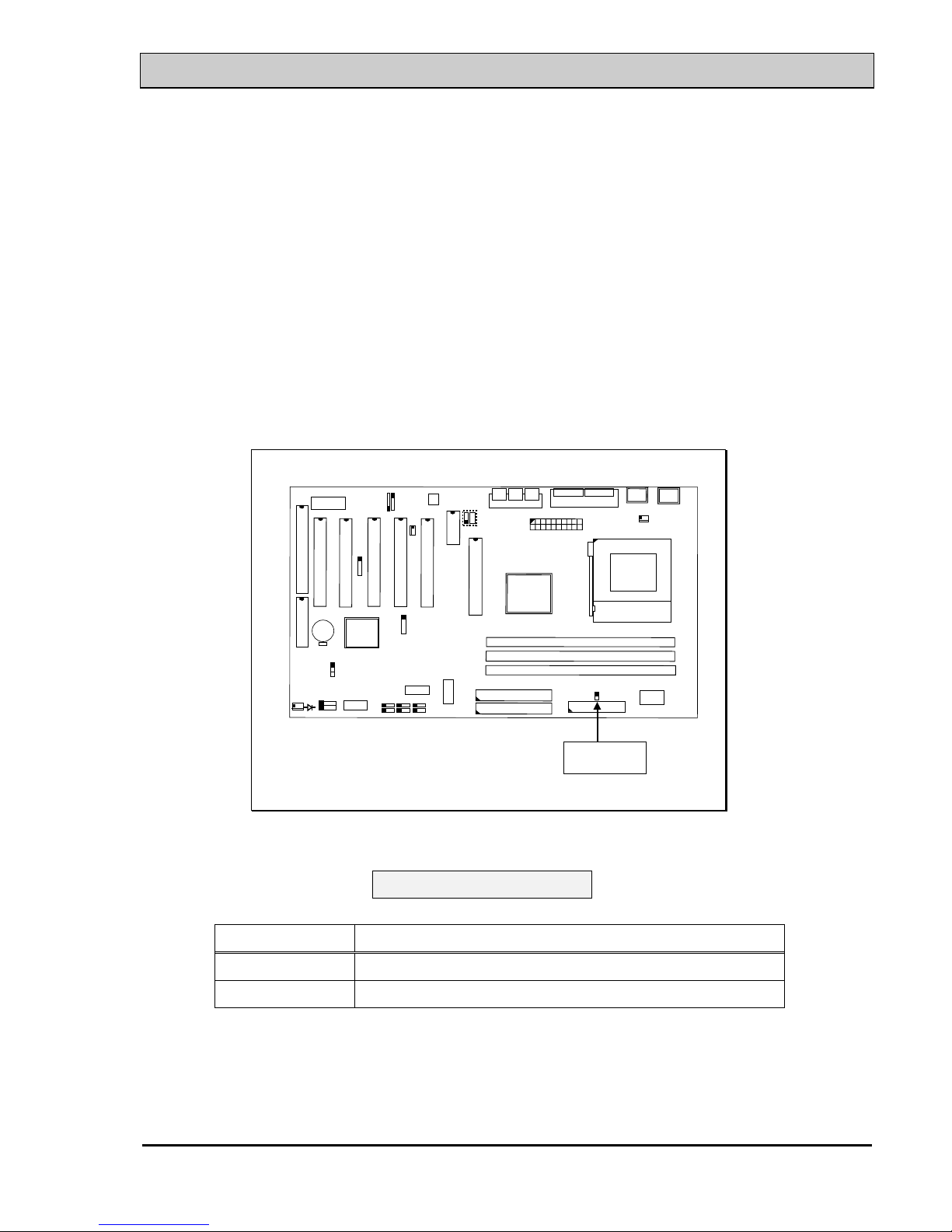
VIA KT133 ATX MAINBOARD HARDWARE SETUP
3-22
(B) JP8: CPU FRONT SIDE BUS SPEED SELECTION (optional)
AMD K7 CPU uses the DDR transfer technology on its data and address busses.
Simply speaking, there are two 100MHz clock inputs connected to the K7 CPU
and the CPU will use the DDR technology to generate the 200MHz front side
system bus speed. (scalable beyond 400MHz in the feature.) Beside the 100MHz
clock frequency for the CPU which you can find from the market, this mainboard
also has the 133MHz designed onboard to support the CPU which might be using
266MHz ( or possibly 533MHz) system bus frequency in the feature. If you find
JP8 on the board, you can use JP8 to select the front side bus speed between
100MHz and 133 MHz for different CPU. Please refer to the following for the
setting of JP8:
JP8
123
4
A
B
C
JP8
Setting of JP8
SETTING SYSTEM BUS CLOCK SPEED
JP8 Open 200MHz (Default, Scalable up to 400MHz)
JP8 Short 266MHz (Scalable up to 533MHz)
Note : You can always refer to Section 4-11 and use the “ Clock By Slight
Adjust) selection field to fine tune the system bus frequency.
Page 39

VIA KT133 ATX MAINBOARD HARDWARE SETUP
3-23
3.5 INSTALLATION OF DEVICE DRIVERS
IMPORTANT NOTE:
Please refer to the following sequence to install the related device drivers:
1. Install the device drivers for the mainboard.
2. Install the device driver for the onboard sound interface.
3. Install the device driver for the hardware monitoring.
A. Install the device drivers for this mainboard:
Please refer to the following procedure to install the device drivers for different
operation system.
Step1. Insert the CD into the CD ROM drive .
Step2. Select "D:\Driver\Mainboard\VIA\Pentium_II" directory. ( Note: "D:"
is the device name of your CD ROM drive)
Step3. Run "SETUP.EXE" in this directory and follow the screen display to
install the mainboard device driver.
B. Install the device driver for the onboard audio interface:
When there is the 3D sound interface installed on this mainboard. Please refer
to the following procedure to install the device drivers: ( you don’t have to
install these device drivers for KT133TXL and KT133BXL mainboards.)
Step1. Insert the CD into the CD ROM drive when Windows requests for the
sound card device driver. (Windows will detects the sound interface)
Step2. Select "D:\Driver\Mainboard\VIA\Sound" directory.
Step3. Run "SETUP.EXE" to install the device driver.
Note: You may need the Service Pack 4 (or the service pack which is newer)
when installing the device driver for Microsoft Windows NT 4.0)
C. Install the device driver for the hardware monitoring:
This mainboard has the hardware monitoring feature designed on the board.
Please refer to the following procedures to install the device driver of the
hardware monitoring.
Step1. Insert the CD disc into the CD ROM drive.
Step2. Change the path to "D:\Driver\Mainboard\VIA\Hardware Monitoring"
Step3. Click on the "SETUP.EXE" icon and follow the screen instruction to
complete the setup.
Page 40

VIA KT133 ATX MAINBOARD AWARD BIOS
4-1
4. AWARD BIOS SETUP
4.1 GETTING STARTED
When you turn the system powered on or reset the PC system, the system BIOS will
enter the POST routines (Power On Self Test routines). POST will execute a series of
diagnostics and system initialization, and you will see the copyright message displayed
on the screen.) In case that there is any error or malfunction detected, the BIOS will
give a series of beeping sound or display the error message on screen.
During the power on self test (POST), the following message appears at the lower left
corner of the screen:
" Press DEL to enter SETUP "
To execute the Award® BIOS CMOS Setup program, please press the DEL key when
you see the above message displayed on the screen, and it will trigger the BIOS setup
utility. When you start the BIOS setup program, you will see the :STANDARD CMOS
SETUP” displayed on the screen as shown in the next page:
Page 41

VIA KT133 ATX MAINBOARD AWARD BIOS
4-2
4.2 MAIN MENU
CMOS Setup Utility – Copyright ( C ) 1984 - 2000 Award Software.
Standard CMOS Setup Frequency / Voltage Control
Advanced BIOS Features Load Optimized Defaults
Advanced Chipset Features Set Supervisor Password
Integrated Peripherals Set User Password
Power Management Setup Save & Exit Setup
PNP/PCI Configuration Exit Without Saving
PC Health Status
ESC : Quit
: Select Item
F10 : Save & Exit Setup (Shift)F2 : Change Color
Time, Date, Hard Disk Type ...
From the screen above, you will find many different setup screen in the BIOS setup
program where you can make the setting of the mainboard configuration. In the
following sections, we are going to give explanation of each selection field. Please
refer to the following section and make proper configuration to your PC system.
Page 42

VIA KT133 ATX MAINBOARD AWARD BIOS
4-3
4.3 CONTROL KEYS
When you have started the BIOS setup program, you will see a list of control key
show at the bottom of the screen. You can use the keyboard to move the selection
bar and choose the proper setting in each selection field. Please refer to the
following for the definition of the control keys:
Arrow Keys : Use the arrow keys to move the cursor to the desired item.
Enter : Select the desired item.
F1 : Display the help screen for the selected feature.
ESC : Exit to the previous screen.
PgUp(-)/PgDn(+): Modify or change the content of the highlighted item.
F5 : Retrieves the previous value from CMOS data,
( only the current page setup will be retrieved ).
F7 : Loads the SETUP default values from BIOS default table,
(only the current page setup will be loaded ).
F10 : Save all changes to CMOS RAM from the MAIN MENU
Page 43

VIA KT133 ATX MAINBOARD AWARD BIOS
4-4
4.4 STANDARD CMOS SETUP
CMOS Setup Utility - Copyright ( C ) 1984 - 2000 Award Software.
Date (mm : dd : yy) : Tue, Aug 1 2000 Item Help
Time (hh : mm : ss : 16 : 03 : 33 Menu Level
IDE Primary Master Press Enter 1316 MB Change this day, month,
IDE Primary Slave Press Enter None Year and century
IDE Secondary Master Press Enter None
IDE Secondary Slave Press Enter None
Drive A 1.44, 3.5 in.
Drive B None
Video EGA/VGA
Halt On All, But Keyboard
Base Memory 640K
Extended Memory 130048K
Total Memory 131072K
IDE Primary / Secondary Master / Slave:
These two selection fields allow you to select the HDD type which is installed on the
primary/secondary IDE port. Move the selection bar to the appropriate field and then
click on the "ENTER" key and the system BIOS will detect the HDD type
automatically.
Drive A /B:
These two selection fields allow you to select the type of the floppy drive. Check the
floppy drive installed in the system and then use this field to select the correct type.
Video:
This selection field allows you to select the display mode. Check the video display
card installed in the PC system and then use this selection field to choose the proper
display mode.
Halt On:
This selection field allows you to decide whether the PC system will be halted when
the system board detects any error during Power On Self Test.
Page 44

VIA KT133 ATX MAINBOARD AWARD BIOS
4-5
Base Memory / Extended Memory / Total Memory
These selection fields show you the capacity of memory which is installed in the PC
system, please refer to the following for the details:
to decide whether the PC system will be halted when the system board detects any
error during Power On Self Test.
Base Memory :This field shows you the memory installed
below the conventional 1MB space.
Extended Memory :This field shows you the memory installed
above the 1MB space.
Total Memory :This field shows you the total memory
installed in the PC system.
Page 45
VIA KT133 ATX MAINBOARD AWARD BIOS
4-6
4.5 ADVANCED BIOS FEATURES
CMOS Setup Utility - Copyright ( C ) 1984 - 2000 Award Software.
Advanced BIOS Features
Virus Warning
:
Disabled Item Help
CPU Internal Cache : Enabled
External Cache : Enabled Menu Level Ø
CPU L2 Cache ECC Checking : Enabled
Quick Power On Self Test : Enabled Allows you to choose
First Boot Device : Floppy The Virus warning
Second Boot Device : HDD-0 Feature for IDE Hard
Third Boot Device : LS120 Disk boot sector
Boot Other Device : Enabled Protection. If this
Swap Floppy Drive : Disabled Function is enabled
Boot Up Floppy Seek : Enabled And some attempt to
Boot Up NumLock Status : On Write data into this
Gate A20 Option : Fast Area, BIOS will show a
Typematic Rate Setting : Disabled Warning message on
Typematic Rate (Chars/Sec) : 6 Screen and alarm beep.
Typematic Delay (Msec) : 250
Security Option : Setup
PS/2 mouse function control : Enable
OS Select For DRAM > 64MB : Non-OS2
HDD S.M.A.R.T Capability : Disabled
Video BIOS Shadow : Enabled
C8000-CBFFF Shadow : Disabled
CC000-CFFFF Shadow : Disabled
D0000-D3FFF Shadow : Disabled
D4000-D7FFF Shadow : Disabled
D8000-DBFFF Shadow : Disabled
DC000-DFFFF Shadow : Disabled
Page 46

VIA KT133 ATX MAINBOARD AWARD BIOS
4-7
Virus Warning
This is the virus intruding warning feature in the BIOS. During and after the
operation system is loaded, any attempt to write to the boot sector or partition
table on the IDE hard disk drive will trigger this feature and give you some
warning messages on the screen and then halt the system. When you find the
message on your screen, please run the anti-virus program to see whether your
system is infected by a virus or not.
Enabled : A warning message will be displayed on the screen when something
attempts to access the boot sector or hard disk partition table.
Disabled : No warning message will appear on the screen when anything
attempts to access the boot sector or hard disk partition table.
CPU Internal Cache / External Cache :
These fields allow you to turn on or turn off the Level 1 and Level 2 cache that
built inside the AMD K7 processors.
CPU L2 Cache ECC Checking:
This option will enable or disable the ECC checking on the CPU L2 cache. The
ECC checking will ensure the accuracy of the data stored on the L2 cache.
Quick Power on Self Test:
The Quick Power On Self Test will skip some test and speed up the boot process. If
you find the system is working normally, you can always enable this feature so that
you don’t have to wait too long on the POST.
First / Second / Third Boot Device :
These fields allow you to decide the sequence of the boot devices.
Swap Floppy Drive :
When enable this option, the device name of the floppy drives will be swapped, For
example, drive A will be treated as drive B, and drive B as Drive A.
Boot Up Floppy Seek :
When enabled, the floppy drive will be initialized during POST.
Page 47

VIA KT133 ATX MAINBOARD AWARD BIOS
4-8
Boot Up NumLock Status
When enabled, the NumLock LED will be lightened after the POST.
Security Option
This selection field allows you to select how to secure the PC system for you.
There are two choice selectable - "Setup" and "System". Before you can apply the
security option to your PC system, you have to select your own ""Supervisor
Password" or "User Password" in the BIOS setup program.
When "Setup" is selected, you will have to input your "Passwords" before you can
start the BIOS setup program. When you select "System", you will be unable to
load the operation system if you don't key-in your personal "password"
PS/2 mouse function control
This mainboard built-in a PS/2™ mouse port. In case that you prefer to connect a
serial mouse to the serial port instead of using the PS/2™ mouse, you may choose
“Disable” in this field so that the IRQ12 can be released for the other devices. If
you are using the PS/2™ mouse, please leave this field “Enabled”.
OS Select For DRAM > 64MB
When you are using the “OS/2™” operating system and the system memory is
more than 64MB, you will have to select the setting to “OS2”, otherwise, leave this
on the default setting “Non-OS2” for all other operating systems.
HDD S.M.A.R.T Capability
There is the HDD which support the S.M.A.R.T. technology (Self Monitoring
Analysis Reporting Technology). If your HDD support the SMART feature, you
may enable this item and it will monitor and report the HDD healthy status to you.
Video BIOS / XXXX-XXXX Shadow
These fields allow you to enable / disable the shadow feature for the Video BIOS
and the appropriate memory segment.
Page 48

VIA KT133 ATX MAINBOARD AWARD BIOS
4-9
4.6 ADVANCED CHIPSET FEATURES
CMOS Setup Utility - Copyright (C) 1984 - 1999 Award Software
Advanced Chipset Features
DRAM Timing By SPD
:
Disabled Item Help
DRAM Clock 100MHz
SDRAM Cycle Length 3 Menu Level Ø
Bank Interleave Disabled
Memory Hole Disabled
PCI Master Pipeline Req Enabled
P2C/C2P Concurrency Enabled
Fast R-W Turn Around Disabled
System BIOS Cacheable Disabled
Video RAM Cacheable Disabled
AGP Aperture Size 64M
AGP 4X Mode Disabled
AGP Driving Control Auto
AGP Driving Value DA
AGP Fast Write Disabled
K7 CLK_CTL Select Optimal
On Chip USB Enabled
USB Keyboard Support Disabled
OnChip Sound Auto
OnChip Modem Auto
CPU to PCI Write Buffer Enabled
PCI Dynamic Bursting Enabled
PCI Master 0 WS Write Enabled
PCI Delay Transaction Enabled
PCI #2 Access #1 Retry Enabled
AGP Master 1 WS Write Disabled
AGP Master 1 WS Read Disabled
This section allows you to configure the system based on the features of the VIA
KT133 chipset. This chipset manages bus speeds and access to system memory
resources, such as DRAM and the external cache. It also coordinates communications
between the conventional ISA bus and the PCI bus. The default settings have been
chosen because they provide the best operating conditions for your system. So please
do not change the default setting unless you have the enough technical background.
Page 49

VIA KT133 ATX MAINBOARD AWARD BIOS
4-10
DRAM Timing By SPD
When enabled, the system BIOS will read the DRAM parameters from the SPD
chip on the DIMM module and set the DRAM timing automatically.
DRAM Clock
This field allows you to select the DRAM access speed to control the memory
performance.
DRAM Cycle Length
When synchronous DRAM is installed, the number of clock cycles of CAS
latency depends on the DRAM timing. Do not reset this field from the default
value specified unless you have the technical background.
BANK Interleave
This field allows you to select how many bank of DRAM is installed on the
mainboard so that the system BIOS will be able to adjust the SDRAM interleave
access mode to optimize the SDRAM performance.
Memory Hole
In order to improve performance, certain space in memory is reserved for ISA
cards. This memory must be mapped into the memory space below 16MB. This
field allows you to enable of disable the memory mapping.
Enabled: The memory space between 15 ~ 16MB will be remapped for ISA cards.
Disabled: No memory will be remapped.
PCI Master Pipeline Req
This field allows you to enable or disable the PCI pipeline access.
P2C/C2P Concurrency
This selection field allows you to enable/disable the PCI to CPU, CPU to PCI
concurrency.
Fast R-W Turn Around
This item controls the DRAM timing. It allows you to enable/ disable the fast
read/write turn around.
System BIOS Cacheable
Selecting Enabled allows caching of the system BIOS ROM at F0000h-FFFFFh,
resulting in better system performance. However, if any program writes to this
memory area, a system error may result.
Page 50

VIA KT133 ATX MAINBOARD AWARD BIOS
4-11
Video RAM Cacheable
Select Enabled allows caching of the video RAM , resulting in better system
performance. However, if any program writes to this memory area, a system error
may result.
AGP Aperture Size
Select the size of Accelerated Graphics Port (AGP) aperture. The aperture is a
portion of the PCI memory address range dedicated for graphics memory address
space. Host cycles that hit the aperture range are forwarded to the AGP without
any translation.
AGP- 4X Mode
This item allows you to enable / disable the AGP-4X Mode. Please make sure
your AGP card supports the 4X AGP display mode before you can select Enable.
AGP Driving Control
This item allows you to adjust the AGP driving force. Choose Manual to key in a
AGP Driving Value in the next selection. Basically, "Auto" is recommended to
avoiding any error in your system.
AGP Driving Value
This item allows you to adjust the AGP driving force.
AGP Fast Write
When Enabled, writes to the AGP(Accelerated Graphics Port) are executed with
fast writing mode.
K7 CLK_CTL Select
This field is used to specify the clock control for ramp rate. The choice selectable
in this field will be Default and Optimal. The selection in the field is highly
depend on the CPU ratio.
OnChip USB
This should be enabled if your system has a USB installed on the system board
and you want to use it. Even when so equipped, if you add a higher performance
controller, you will need to disable this feature.
USB Keyboard Support
Select Enabled if your system contains a Universal Serial Bus (USB) controller
and you have a USB keyboard.
OnChip Sound
Page 51

VIA KT133 ATX MAINBOARD AWARD BIOS
4-12
This item allows you to control the onboard AC 97 audio.
OnChip Modem
This item allows you to control the onboard MC 97 Modem.
CPU to PCI Write buffer
When this field is Enabled, writes from the CPU to the PCI bus are buffered, to
compensate for the speed differences between the CPU and the PCI bus. When
Disabled, the writes are not buffered and the CPU must wait until the write is
complete before starting another write cycle.
PCI Dynamic Bursting
When Enabled, every write transaction goes to the write buffer. Burstable
transactions then burst on the PCI bus and non-burstable transactions don’t.
PCI Master 0 WS Write
When Enabled, writes to the PCI bus are executed with zero wait states.
PCI Delay Transaction
The chipset has an embedded 32-bit posted write buffer to support delay
transactions cycles. Select Enabled to support compliance with PCI specification
version 2.1.
PCI#2 Access #1 Retry
When disabled, PCI#2 will not be disconnected until access finishes (difault).
When enabled, PCI#2 will be disconnected if max retries are attempted without
success.
AGP Master 1 WS Write
When Enabled, writes to the AGP(Accelerated Graphics Port) are executed with
one wait states.
AGP Master 1 WS Read
When Enabled, read to the AGP (Accelerated Graphics Port) are executed with
one wait states.
Page 52

VIA KT133 ATX MAINBOARD AWARD BIOS
4-13
4.7 INTEGRATED PERIPHERALS
CMOS Setup Utility - Copyright (C) 1984 - 1999 Award Software
Integrated Peripherals
On-Chip IDE Chanel0
Enabled Item Help
On-Chip IDE Chanel1 Enabled
IDE Prefetch Mode Enabled Menu Level Ø
Primary Master PIO Auto
Primary Slave PIO Auto
Secondary Master PIO Auto
Secondary Slave PIO Auto
Primary Master UDMA Auto
Primary Slave UDMA Auto
Secondary Master UDMA Auto
Secondary Slave UDMA Auto
Init Display first PCI Slot
IDE HDD Block Mode Enabled
Onboard FDD Controller Enabled
Onboard Serial Port 1 Auto
Onboard Serial Port 2 Auto
UART 2 Mode Standard
IR Function Duplex Half
TX, RX inverting enable No, Yes
Onboard Parallel Port 378/IRQ7
Onboard Parallel Mode Normal
ECP Mode Use DMA 3
Parallel Port EPP Type EPP 1.9
Onboard Legacy Audio Enabled
Sound Blaster Disabled
SB I/O Base Address 220H
SB IRQ Select IRQ 5
SB DMA Select DMA 1
MPU-401 Enabled
MPU-401 I/O Address 330-333H
Game Port (200-207H) Enabled
OnChip IDE Channel 0/1
The chipset contains a PCI IDE interface with support for two IDE channels.
Select Enabled to activate the primary IDE interface. Select Disabled to
deactivate this interface.
Page 53

VIA KT133 ATX MAINBOARD AWARD BIOS
4-14
IDE Prefetch Mode
The onboard IDE drive interfaces supports IDE prefetching for faster drive
accesses. If you install a primary and/or secondary add-in IDE interface, set this
field to Disabled if the interface does not support prefetching.
Primary/Secondary, Master/Slave PIO
The four IDE PIO (Programmed Input/Output) fields let you set a PIO mode (0-4)
for each of the four IDE devices that the onboard IDE interface supports. Modes 0
through 4 provide successively increased performance. In Auto mode, the system
automatically determines the best mode for each device.
Primary/Secondary, Master/Slave UDMA
Ultra DMA/66 implementation is possible only if your IDE hard drive supports it
and the operating environment includes a DMA driver (Windows 98 OSR2 or a
third-party IDE bus master driver). If your hard drive and your system software
both support Ultra DMA/66, select Auto to enable BIOS support.
Init Display First
This field allows you to decide to active whether PCI Slot of VGA card or AGP
first.
IDE HDD Block Mode
Block mode is also called block transfer, multiple commands, or multiple sector
read/write. If your IDE hard drive supports block mode (most new drives do),
select Enabled for automatic detection of the optimal number of block read/writes
per sector the drive can support.
Onboard FDD Controller
Select Enabled if your system has a floppy disk controller (FDC) installed on the
system board and you want to use it. If you install add-in FDC or the system has
no floppy drive, select Disabled in this field.
Onboard Serial Port 1/Port 2
These two selection fileds allow you to select the I/O address and corresponding
interrupt for the first and second serial ports.
UART 2 Mode
This item allows you to select which mode for the Onboard Serial Port 2.
Page 54

VIA KT133 ATX MAINBOARD AWARD BIOS
4-15
IR Function Duplex
This item allows you to select the IR half/full duplex funcion.
TX,RX inverting enable
This item allow you to enable the TX, RX inverting which depends on different
H/W requirement. This field is not recommended to change its default setting for
avoiding any error in your system.
Onboard Parallel Port
This item allows you to determine onboard parallel port controller I/O address
setting.
Onboard Parallel Port Mode
Select an operating mode for the onboard parallel (printer) port. Select Normal,
Compatible, or SPP unless you are certain your hardware and software both
support one of the other available modes.
ECP Mode Use DMA
This item allows you to select a DMA channel for the parallel port for use during
ECP mode.
EPP Mode Select
This field allows you to select EPP port type between 1.7 or 1.9.
Onboard Legacy Audio
This field controls the onboard legacy audio.
Sound Blaster
SB I/O Base Address
SB IRQ Select
SB DMA Select
MPU-401
MPU-401 I/O Address
Game Port (200-207H)
Page 55

VIA KT133 ATX MAINBOARD AWARD BIOS
4-16
4.8 POWER MANAGEMENT SETUP
CMOS Setup Utility - Copyright (C) 1984 - 1999 Award Software
Power Management Setup
ACPI Function
Disabled Item Help
Power Management Press Enter Menu Level Ø
ACPI Suspend Type S1 (POS)
PM Control By APM Yes
Video Off Option Suspend -> off
Video Off Method Blank Screen
Modem Use IRQ 3
Soft-Off by PWRBTN Instant – off.
Wake-Up Events Press Enter
The Power Management Setup allows you to configure you system to most effectively
save energy while operating in a manner consistent with your own style of computer
use.
ACPI function
This item allows you to enable/disable the Advanced Configuration and Power
Management (ACPI).
Power Management:
When click the "Enter" key on this selection field, the following setup screen will
be triggered:
Power Management
User Define Item Help
HDD Power Down Disabled Menu Level Ø
Doze Mode Disabled
Suspend Mode Disabled
Power Management
Page 56

VIA KT133 ATX MAINBOARD AWARD BIOS
4-17
Disable No power management. Disable all power saving modes.
Min. Power Saving
Minimum power management. Doze Mode = 1 hr.
Standby Mode = 1 hr., Suspend Mode = 1 hr., and HDD
Power Down = 15 min.
Max. Power Saving
Maximum power management -- ONLY AVAILABLE
FOR SL CPU. Doze Mode = 1 min., Standby Mode = 1
min., Suspend Mode = 1 min., and HDD Power Down =
1 min.
User Defined
Allows you to set each mode individually. When not
disabled, each of the ranges are from 1 min. to 1 hr.
except for HDD Power Down which ranges from 1 min.
to 15 min. and disable.
HDD Power Down
When enabled and after the set time of system inactivity, the hard disk drive will
be powered down while all other devices remain active.
Doze Mode
When enabled and after the set time of system inactivity, the CPU clock will run
at slower speed while all other devices still operate at full speed.
Suspend Mode
When enabled and after the set time of system inactivity, all devices except the
CPU will be shut off.
PM Control by APM
When enabled, an Advanced Power Management device will be activated to
enhance the Max. Power Saving mode and stop the CPU internal clock. If
Advance Power Management (APM) is installed on your system, selecting Yes
gives better power savings.
Video Off Option
When enabled, this feature allows the VGA adapter to operate in a power saving
mode.
Always On Monitor will remain on during power saving modes.
Page 57

VIA KT133 ATX MAINBOARD AWARD BIOS
4-18
Suspend --> Off Monitor blanked when the systems enters the
Suspend mode.
Susp,Stby --> Off Monitor blanked when the system enters either
Suspend or Standby modes.
All Modes -->
Off
Monitor blanked when the system enters any power
saving mode.
Video Off Method
This determines the manner in which the monitor is blanked.
V/H
SYNC+Blank
This selection will cause the system to turn off the
vertical and horizontal synchronization ports and
write blanks to the video buffer.
Blank Screen This option only writes blanks to the video buffer.
DPMS Select this option if your monitor supports the
Display Power Management Signaling (DPMS)
standard of the Video Electronics Standards to select
video power management values.
MODEM Use IRQ
This determines the IRQ in which the MODEM can use for power saving purpose.
This mainboard has the ACPI feature designed on the board and it will “wakeup”
automatically when it detects the incoming modem Ring-in signal. Before you can
use the Ring-in signal to wakeup your PC system, you have to install the
“External” modem to your PC system and tell the PC system which serial port
connects to the modem by selecting the IRQ in this field. ( officially, COM 1 uses
IRQ4, and COM 2 uses IRQ3 )
Soft-Off by PWRBTN
Pressing the power button for more than 4 seconds forces the system to enter the
Soft-Off state when the system has “hung.”.
Suspend Type: (Default setting: "Stop Grant" )
Page 58

VIA KT133 ATX MAINBOARD AWARD BIOS
4-19
This field allows to select the suspend type, you can choose the CPU Stop Grand
Suspend or the PwrOn Suspend.
Wake Up Events:
When click the "Enter" key on this selection field, the following setup screen will
be triggered:
VGA
OFF Item Help
LPT & COM LPT / COM Menu Level Ø
HDD & FDD ON
PCI Master OFF
Wake Up On LAN/Ring Disabled
RTC Alarm Resume 0
Date (of Month) 0
Resume Time (hh:mm:ss) 0 0 0
Primary INTR ON
IRQs Activity Monitoring Press Enter
VGA
When Enabled, you can set the VGA awakens the system.
LPT & COM
When On of LPT & COM, any activity from one of the listed system peripheral
devices or IRQs wakes up the system.
HDD & FDD
When On of HDD & FDD, any activity from one of the listed system peripheral
devices wakes up the system.
PCI Master
When On of PCI Master, any activity from one of the listed system peripheral
devices wakes up the system.
Wake Up On LAN/Ring
An input signal on the serial Ring Indicator (RI) line (in other words, an incoming
call on the modem) awakens the system from a soft off state.
RTC Alarm Resume
Page 59

VIA KT133 ATX MAINBOARD AWARD BIOS
4-20
When enabled, you can use the following two fields to select the time and date to
wake up the PC system from power saving mode.
Date (of Month)
Resume Time (hh:mm:ss)
When RTC Alarm Resume is enabled, your can set the date and time at which the
RTC (real-time clock) alarm awakens the system from Suspend mode.
IRQs Activity Monitoring
The following is a list of IRQ’s, Interrupt ReQuests, which can be exempted
much as the COM ports and LPT ports above can. When an I/O device wants to
gain the attention of the operating system, it signals this by causing an IRQ to
occur. When the operating system is ready to respond to the request, it interrupts
itself and performs the service.
When set On, activity will neither prevent the system from going into a power
management mode nor awaken it.
IRQ3 (COM 2)
Enabled Item Help
IRQ4 (COM 1) Enabled Menu Level Ø
IRQ5 (LPT 2) Enabled
IRQ6 (Floppy Disk) Enabled
IRQ7 (LPT 1 Disk) Enabled
IRQ8 (RTC Alarm) Disabled
IRQ9 (IRQ2 Redir) Disabled
IRQ10 (Reserved) Disabled
IRQ11 (Reserved) Disabled
IRQ12 (PS/2 Mouse) Enabled
IRQ13 (Coprocessor) Enabled
IRQ14 (Hard Disk) Enabled
IRQ15 (Reserved) Disabled
Page 60

VIA KT133 ATX MAINBOARD AWARD BIOS
4-21
4.9 PNP/PCI CONFIGURATION
CMOS Setup Utility - Copyright (C) 1984 - 1999 Award Software
PnP/PCI Configuration
PnP OS Installed :
No Item Help
Reset Configuration Data : Disabled
Resources Controlled By : Auto (ESCD) Menu Level Ø
X IRQ Resources : Press Enter
X DMA Resources : Press Enter Select yes if you are
Using a plug and play
PCI/VGA Palette Snoop : Disabled Capable operating
Assign IRQ For VGA : Enabled system. Select No if
Assign IRQ for USB : Enabled you need the BIOS to
configure non-boot
device.
PNP OS Installed
This item allows you to determine PnP OS is installed or not.
Reset Configuration Data
Normally, you leave this field Disabled. Select Enabled to reset Extended System
Configuration Data (ESCD) when you exit Setup if you have installed a new add-on
and the system reconfiguration has caused such a serious conflict that the operating
system can not boot.
Resource controlled by
The Award Plug and Play BIOS has the capacity to automatically configure all of
the boot and Plug and Play compatible devices. However, this capability means
absolutely nothing unless you are using a Plug and Play operating system such as
Windows98.
Page 61

VIA KT133 ATX MAINBOARD AWARD BIOS
4-22
IRQ Resources
When resources are controlled manually, assign each system interrupt a type,
depending on the type of device using the interrupt
Legacy ISA Devices compliant with the original PC AT bus specification,
requiring a specific interrupt ( such as IRQ4 for serial port 1). PCI/ISA PnP
Devices compliant with the Plug and Play standard, whether designed for PCI or
ISA bus architecture.
DMA Resources
When resources are controlled manually, assign each system DMA channel as one
of the following types, depending on the type of device using the interrupt.
Legacy ISA Devices compliant with the original PC AT bus specification,
requiring a specific interrupt ( such as IRQ4 for serial port 1). PCI/ISA PnP
Devices compliant with the Plug and Play standard, whether designed for PCI or
ISA bus architecture.
PCI/VGA Palette Snoop
Leave this field at Disabled all the time
Assign IRQ For VGA/USB:
Enable/Disable to assign IRQ for USB/VGA
Page 62

VIA KT133 ATX MAINBOARD AWARD BIOS
4-23
4.10 PC HEALTH STATUS
CMOS Setup Utility - Copyright (C) 1984 - 1999 Award Software
PC Health Status
Current CPU Temp. 40
$
C/104$F Item Help
Current System Temp. 22$C/71$F
Current CPUFAN1 Speed 5080 RPM Menu Level Ø
Current CPUFAN2 Speed 0 RPM
Vcore 1.83 V
2.5V 2.57 V
3.3V 3.38
5V 4.92 V
12V 12.48V
The table above allows you to monitor the PC system healthy status. You can check on
the related field and monitor the status like voltage, Temperature … etc.
Current CPU Temp.
This field will show you the current CPU temperature
Current System Temp.
This field will show you the current temperature inside the PC system.
Current CPUFAN1 Speed
This field will show you the current CPU Cooling FAN1 speed.
Current CPUFAN2 Speed
This field will show you the current CPU Cooling FAN2 speed.
Vcore
This field and the files blow show you the current system voltage
Page 63

VIA KT133 ATX MAINBOARD AWARD BIOS
4-24
4.11 FREQUENCY/VOLTAGE CONTROL
CMOS Setup Utility - Copyright (C) 1984 - 1999 Award Software
Frequency/Voltage Control
Auto Detact DIMM/PCI Clk Disabled Item Help
Spread Spectrum Disabled
Clock By Slight Adjust 100 Menu Level Ø
Auto Detect DIMM/PCI Clk
When “Enabled” is selected, the mainboard will detect the presence of devices on
DIMM and PCI slots. When there is no device presented on some of the PCI or
DIMM connector, the clock on the related DIMM and PCI slot will be disabled to
reduce the Electro-Magnetic Interference (EMI).
Spread Spectrum
When Spread Spectrum is enabled, the EMI radiation on this mainboard will be
reduced.
Clock By Slight Adjust
You can use this field to adjust the front side system bus clock speed of the CPU.
The adjustment of the clock frequency in this field is +/- 1MHz increment so you
can fine tune the system performance.
Page 64

VIA KT133 ATX MAINBOARD AWARD BIOS
4-25
4.12 LOAD OPTIMIZED DEFAULTS
CMOS Setup Utility - Copyright (C) 1984 - 1999 Award Software
Standard CMOS Features Frequency / Voltage Control
Advanced BIOS Features Load Optimized Defaults
Advanced Chipset Features Set Supervisor Password
Integrated Peripherals Set User Password
Power Management Setup Save & Exit Setup
PNP/PCI Configuration Exit Without Saving
PC Health Status
ESC : Quit
: Select Item
F10 : Save & Exit Setup
Time, Date, Hard Disk Type ...
There is the CMOS memory on the mainboard which can be used to store the system
settings. In case that you don't know how to use the Award BIOS setup program to
select the settings, you may use this field to load the optimized default which is defined
in the system BIOS. Basically, the optimized default is chosen by the factory and it will
give a series of parameters to make sure the best reliability and performance.
If you lost the CMOS data or you don’t know how to complete the setup procedure, you
may use this option to load the Optimized default values from the BIOS default table.
The optimized default value is the suggested setting which will give the best reliability
and also the good performance.
Incase that the CMOS data is corrupted, or if you made some CMOS setting and found
that the PC system becomes very stable, then you may try to load the optimized default
value and the CMOS will be changed to its default setting.
Page 65

VIA KT133 ATX MAINBOARD AWARD BIOS
4-26
4.13 SET SUPERVISOR PASSWORD
CMOS Setup Utility - Copyright (C) 1984 - 1999 Award Software
Standard CMOS Features Frequency / Voltage Control
Advanced BIOS Features Load Optimized Defaults
Advanced Chipset Features Set Supervisor Password
Integrated Peripherals Set User Password
Power Management Setup Save & Exit Setup
PNP/PCI Configuration Exit Without Saving
PC Health Status
ESC : Quit
: Select Item
F10 : Save & Exit Setup
Time, Date, Hard Disk Type ...
The “SUPERVISOR PASSWORD” will be used to check the authority when power-on
the PC system. The Supervisor Password will have different function according to the
"Security Option" setup in Section 4.5:
When "Setup" is selected in Security Option:
If you want to change the BIOS setting, you will have to key-in the Supervisor
Password so that you can start the BIOS setup program and change the system
setting..
When "System" is selected in Security Option:
When turn on the PC system, it will request you to enter the Password. Without
the correct password, the PC system will stop and the operation system will not be
loaded.
Page 66

VIA KT133 ATX MAINBOARD AWARD BIOS
4-27
4.14 SET USER PASSWORD
CMOS Setup Utility - Copyright (C) 1984 - 1999 Award Software
Standard CMOS Features Frequency / Voltage Control
Advanced BIOS Features Load Optimized Defaults
Advanced Chipset Features Set Supervisor Password
Integrated Peripherals Set User Password
Power Management Setup Save & Exit Setup
PNP/PCI Configuration Exit Without Saving
PC Health Status
ESC : Quit
: Select Item
F10 : Save & Exit Setup
Time, Date, Hard Disk Type ...
The User Password can be used to check the user's authority. However, this password
entry is somewhat different to the "SUPERVISOR PASSWORD" mentioned in
previous section. The User Password will have different function according to the
"Supervisor Password" and the "Security Option" setup in Section 4.5:
A. When there is the password stored in the "SUPERVISOR PASSWORD"
1. When "Setup" is selected in Security Option:
When you use the "User Password" to log into the BIOS setup program, you can
only select "User Password", "SAVE & EXIT SETUP" and "EXIT WITHOUT
SAVING" from the main menu. (Use Supervisor Password to log into the PC
system, you will have the complete right to on all BIOS settings.)
2. When "System" is selected in Security Option:
When turn on the PC system, it will request you to enter the Password. Without
correct password, PC system will stop and the operation system won't be loaded.
Page 67

VIA KT133 ATX MAINBOARD AWARD BIOS
4-28
B. When there is no password stored in the "SUPERVISOR PASSWORD"
1. When "Setup" is selected in Security Option:
Users can use the "User Password" to log into the BIOS setup program, and they
can make all the change in the BIOS setup program.
2. When "System" is selected in Security Option:
When turn on the PC system, it will request you to enter the Password. Without
the correct password, the PC system will stop and the operation system will not
be loaded.
Page 68

VIA KT133 ATX MAINBOARD AWARD BIOS
4-29
4.15 SAVE & EXIT SETUP / EXIT WITHOUT SAVING
CMOS Setup Utility - Copyright (C) 1984 - 1999 Award Software
Standard CMOS Features Frequency / Voltage Control
Advanced BIOS Features Load Optimized Defaults
Advanced Chipset Features Set Supervisor Password
Integrated Peripherals Set User Password
Power Management Setup Save & Exit Setup
PNP/PCI Configuration Exit Without Saving
PC Health Status
ESC : Quit
: Select Item
F10 : Save & Exit Setup
Time, Date, Hard Disk Type ...
Save & Exit Setup:
This option will save all setup values to CMOS RAM & EXIT SETUP routine.
Move the selection bar to “SAVE & EXIT SETUP” and pressing “Enter” key, then
types “Y” and “Enter” key, the values will be saved and all the information will be
stored in the CMOS memory.
Exit Without Saving
This item exit the setup routine without saving any changed values to CMOS RAM,
When you do not want to save your change to the CMOS memory, you may choose
to run this option and the setting what you made in the BIOS setup routine will be
given away.
Page 69

VIA KT133 ATX MAINBOARD BIOS UPGRADE
5-1
5. How to Update the System BIOS
Before we start to discuss system BIOS update, there are some important issues
which you need to pay attention on it:
1. You can not exchange the system BIOS with another mainboard:
The system BIOS on different mainboard are different. If you take the system
BIOS from another mainboard and have it installed on this mainboard, you
may find that the mainboard fail to boot. Even the mainboard from the same
manufacturer, the content of the system BIOS can be different. So please do
not exchange the system BIOS.
2. Where to get the updated BIOS?
You can visit the web page of the supplier and down load the updated system
BIOS. Please note that you will “kill” the PC system if you have the wrong
BIOS written into the PC system. So please be sure to double check the
system BIOS before you can use it to update the system BIOS.
3. No interruption is allowed during the BIOS updating:
When the BIOS updating, please do not restart the PC system or turn the
power off. Otherwise, you will have a fragmentary system BIOS in your PC
system and it will make you unable to start the PC system. If you reset or
power off the PC system while the system BIOS is updating, you may have to
send the PC system to the suppler for troubleshooting because you do not
have the system BIOS in the PC system.
4. Do not change the onboard flash ROM:
The flash ROM is the storage device which is designed on the mainboard to
store the system BIOS. There are different kinds of the flash ROM selling in
the market. They have different capacity and different architecture. If you
install improper flash ROM onto the mainboard, it may cause unexpected
damage to the mainboard. So please never change the flash ROM on the
mainboard, otherwise, the warranty will be void.
Page 70

VIA KT133 ATX MAINBOARD BIOS UPGRADE
5-2
SYSTEM BIOS UPDATE PROCEDURE
Step 1. Download the system BIOS from the web page:
1. Visit the following web page:
http://www.azza.com.tw
2. Select “TECH SUPPORT”
3. Down load “AWDFLASH.EXE” program.
4. Scroll the screen downward and find the KT133TX mainboard.
5. Select the BIOS and start to down load. (Suppose the file name is
KT133I.BIN)
Step 2. Prepare for the BIOS updating:
1. Windows is the multi task environment and some unexpected interruption
can be occurred and stop the BIOS updating. Since no interruption is
allowed during the BIOS updating. so the BIOS updating can not be made
under the Windows environment.
2. Get a floppy diskette and put it into the floppy disk drive.
3. Key-in the following command under the DOS prompt:
C:> FORMAT A:/S
4. When the diskette formatting is completed, have the files which you down
loaded from the web page copied into the floppy diskette. (KT133I.BIN and
AWDFLASH.EXE).
Page 71

VIA KT133 ATX MAINBOARD BIOS UPGRADE
5-3
Step 3. Start to update the system BIOS:
1. Have the diskette which we made in Step 2 inserted in the floppy disk
drive..
2. Start the PC system and click on the “del” key to start the BIOS setup
program. Select the “Advanced BIOS features” and then make sure to select
the floppy disk drive is the first boot device.
3. Having made the boot sequence selection, save the setup and restart the PC
system.
4. When the DOS prompt “A:>” appears, run AWDFLASH.EXE program.
(You can use “AWDFLASH /?” to more detail of the program.)
5. When you have started the “AWDFLASH.EXE”, it will ask you to input the
file name of the new BIOS. Key-in “KT133I.BIN” and then click the
“ENTER” key.
6. When you see the message - Do you want to save BIOS (Y/N)?. you may
choose “Y” to have the onboard BIOS copied in to the floppy diskette. If
you do not want to make the backup copy of the onboard BIOS, simply
chose “N” and start to update the system BIO. (if you want to make a
backup copy of the onboard system BIOS, then select “Y” and then give a
file name to the backup copy.)
7. You will see from the screen whether you are going to start the BIOS
update. If you are sure that the new BIOS is correct and nothing is wrong,
chose “Y” to start the BIOS update. ( you can chose “N” and terminate the
BIOS update program.)
8. During the BIOS updating, you will see the “Programming Flash Memory”
message display on the screen. (IMPORTANT: you can not stop or reset
the PC system when the BIOS is updating.)
9. When the BIOS update is completed, remove the floppy diskette from the
floppy disk drive and restart the PC system..
10. When you see the PC system start to boot, it indicate that the BIOS update
is successful.
11. Click the “del” key during the Power On Self Test to trigger the BIOS setup
program..
12. Chose "Load Optimized Default" and have the default setting written into
the CMOS memory.
13. Chose "Save and Exit" and then restart the PC system.
14. Having finished the procedures above, the BIOS update is completed.
 Loading...