

Page 1
X
FNER Expandable (Modular) Routing Switches
Installation & Operation Manual
Page 2

Although every effort has been taken to ensure the accuracy of this document it may be necessary, without notice, to make amendments or correct omissions.
Specications subject to change without notice.
Page 3

TABLE OF CONTENTS
Page
1. SYSTEM OVERVIEW ................................................................................................................................ 1-1
1.1. System Features ............................................................................................................................... 1-1
1.2. User Permission Feature ................................................................................................................... 1-1
1.3. Access Control Feature ..................................................................................................................... 1-1
1.4. System Upgrades .............................................................................................................................. 1-1
1.5. Modules ............................................................................................................................................. 1-1
2. CONNECTIONS & PROTOCOLS ............................................................................................................. 2-1
2.1. AC Connections................................................................................................................................. 2-1
2.2. RF Signals ......................................................................................................................................... 2-1
2.3. Control Ports...................................................................................................................................... 2-1
2.4. MPC 128 Control In Port Connection ................................................................................................ 2-2
2.5. Ethernet Port ..................................................................................................................................... 2-3
2.6. Ethernet Command Protocol ............................................................................................................. 2-3
3. FRONT PANEL BASICS ........................................................................................................................... 3-1
3.1. Front Panel Interface ......................................................................................................................... 3-1
3.2. Main Menu ......................................................................................................................................... 3-1
3.3. Front Panel Hierarchy & Page References ....................................................................................... 3-1
4. INITIALIZING SYSTEM FROM THE KEYPAD .......................................................................................... 4-1
4.1. Communications Setup ..................................................................................................................... 4-1
4.2. Serial Interface Menu ........................................................................................................................ 4-1
4.3. Ethernet Conguration Menu............................................................................................................. 4-3
4.4. DHCP On/Off ..................................................................................................................................... 4-3
4.5. COMM Port/Password Menu ............................................................................................................. 4-4
5. CROSSPOINT CONNECTIONS ................................................................................................................ 5-1
5.1. Monitor a Connection ........................................................................................................................ 5-1
5.2. Changing a Connection ..................................................................................................................... 5-1
5.3. Locking & Unlocking Connections ..................................................................................................... 5-1
6. RS-485 ....................................................................................................................................................... 6-1
6.1. Why an RS-485 Section? .................................................................................................................. 6-1
6.2. RS-485 Basics ................................................................................................................................... 6-1
6.3. Which Ports are RS-485 .................................................................................................................... 6-2
6.4. Summary ........................................................................................................................................... 6-2
6.5. Front Panel RS-485 Termination ....................................................................................................... 6-2
7. FACTORY CONFIGURATION SETTINGS ................................................................................................7-1
7.1. System Options Menu ....................................................................................................................... 7-1
7.2. Conguration Menu ........................................................................................................................... 7-1
7.3. Factory Settings Code Number ......................................................................................................... 7-2
7.4. System Setup Menu .......................................................................................................................... 7-2
7.5. Matrix Size ......................................................................................................................................... 7-2
7.6. Model ................................................................................................................................................. 7-3
7.7. Load Firmware...................................................................................................................................7-4
7.8. Exiting Download Mode ..................................................................................................................... 7-5
7.9. Firmware Upgrade Kit........................................................................................................................ 7-5
7.10. Firmware Download Instructions ....................................................................................................... 7-5
7.11. Firmware Download Preparation ....................................................................................................... 7-5
7.12. Ethernet or Serial Port Download? .................................................................................................... 7-5
7.13. Why Download Firmware? ................................................................................................................ 7-5
7.14. Why Is Downloading Failing? ............................................................................................................ 7-5
7.15. Features Menu ..................................................................................................................................7-7
7.16. Set Control Mode............................................................................................................................... 7-7
7.17. Options Menu .................................................................................................................................... 7-7
FLEXNET – FNER Expandable (Modular) Routing Switches – Installation & Operation Manual i
Page 4

7.18. SNMP Menu ...................................................................................................................................... 7-8
7.19. Port Access Control Enable/Disable .................................................................................................. 7-9
8. ACCESS CONTROL ..................................................................................................................................8-1
8.1. Access Control Overview .................................................................................................................. 8-1
8.2. System Access .................................................................................................................................. 8-1
8.3. Port Access Control Enable/Disable .................................................................................................. 8-1
8.4. Access Control Menu ........................................................................................................................ 8-2
8.5. Keypad Access Control ..................................................................................................................... 8-2
8.6. Logging In & Logging Out .................................................................................................................. 8-3
8.7. User Accounts ................................................................................................................................... 8-4
8.8. Access Control Setup Menu .............................................................................................................. 8-4
8.9. Dening User Names & Passwords .................................................................................................. 8-4
8.10. Dening Group Output Permissions .................................................................................................. 8-5
8.11. Factory Defaults for Access Control ..................................................................................................8-6
8.12. Admin Account................................................................................................................................... 8-6
9. SPECIFICATIONS ..................................................................................................................................... 9-1
9.1. Specications .................................................................................................................................... 9-1
10. SERVICE & SUPPORT ............................................................................................................................ 10-1
10.1. Contact ATX Networks .....................................................................................................................10-1
10.2. Warranty Information ....................................................................................................................... 10-1
11. APPENDIX ............................................................................................................................................... 11-1
11.1. General Problems ............................................................................................................................ 11-1
11.2. Front Panel LEDs ............................................................................................................................ 11-1
11.3. Problems with Crosspoint Connections ........................................................................................... 11-2
11.4. Serial Port Problems........................................................................................................................ 11-2
11.5. Ethernet Problems ........................................................................................................................... 11-3
ii FLEXNET – FNER Expandable (Modular) Routing Switches – Installation & Operation Manual
Page 5

SYSTEM OVERVIEW
1. System Overview
Thank you for purchasing an FNER Expandable Routing Switch. FLEXNET’s FNER series switches are based on the same
technology as our popular FNEM Series Modular Programmable RF Switches. They were developed to address the increasing
need for expandable RF switching in telecommunication network signal processing centers and are equally suitable for audio/
video, baseband, data, IF, and RF switching requirements.
The FNER is perfect for centralized test and measurement applications in networks that are monitoring large numbers of RF
signals. Each FNER system is compatible with most monitoring and control systems and can be expanded in 16x1 modules
up to a maximum capacity of 128x1. Control of the FNER occurs from a front panel keypad or remotely via computer (serial
or TCP/IP). The excellent RF performance of the FNER is achieved through proprietary technology.
Each system is supplied with a control unit. From this unit, an operator may make RF signal routing changes or check to see
the input currently dened. The control unit is also supplied with serial (RS-232 and RS-422/485) and Ethernet (10BaseT
TCP/IP) control ports to allow remote control of the FNER system.
This operating manual attempts to familiarize you with the different capabilities and features of FNER systems.
1.1 System Features
FLEXNET systems are equipped with many standard features that make the system highly congurable for our customers.
CHAPTER 1: SYSTEM OVERVIEW
1.2 User Permission Feature
The FNER system features user permissions. This is congured by setting up user accounts with names, passwords, and
permissions. These accounts set limits to what system setting users can change. After an account is set up by the administrator,
the user logs into the system and the settings in their account determine if they can change the output or not.
The primary benet of our access control feature is users are protected from the unintentional or accidental RF connection
change. This system is much more robust in a larger system with multiple inputs and outputs, but access control for an FNER
still gives the option to require login before the output can be changed.
1.3 Access Control Feature
The FLEXNET matrix system also features access control. The control module in our system has four ports of access that are
available for user interface. These are a front panel keypad, Ethernet port, Telnet port, and a Control In port. Users can control
the system from any one of these access ports.
Access control can be turned on or off for each one of these ports. This feature enables or disables the login requirements
before a user may make a change to the output.
If access control is enabled for a port, the user must rst log in with a user name and password before any changes can be
made. With different access control settings, a user could change the connections from a serial port but be required to log in
with permissions from the keypad or the Ethernet port.
1.4 System Upgrades
You can even upgrade your system later to increase the number of inputs available to you. Each FNER system can be
congured for up to 128 inputs. Contact us at ATX Networks and we can help you with your growing communication needs.
1.5 Modules
Two types of modules comprise an FNER system: an MCP 128 (8x1) controller and a 16x1 switching module. Every FNER
system consists of one MPC 128 and 1 or more switching modules. A minimal FNER switching system consists of a single
MPC 128 and one switching module.
1.5.1 MPC 128
The MCP 128 provides master control capability via the front panel keypad/LCD display or computer interface (serial or TCP/
IP). The unit receives commands from the keypad or computer and controls the individual switching modules. From this unit,
an operator can make routing changes or check to see the path currently congured.
FLEXNET – FNER Expandable (Modular) Routing Switches – Installation & Operation Manual 1-1
Page 6

CHAPTER 1: SYSTEM OVERVIEW
1.5.2 FNER Switching Module
The FNER Switching Module is a 16x1 unit that utilizes solid state switching elements to provide seamless switching speeds
(nanoseconds). Up to eight switching modules may be combined in a single FNER system. The total number of switching
modules required for a system is equal to the total number of system inputs divided by 16. Every switching module is
equipped with two inter-module serial ports (“CONTROL-IN” and “CONTROL-OUT”) that are used for communication with
other FNER modules.
Figure 1: MCP 128 (8x1) Controller
Figure 2: 16x1 Switching Module
1-2 FLEXNET – FNER Expandable (Modular) Routing Switches – Installation & Operation Manual
Page 7

CONNECTIONS & PROTOCOLS
2. Connections & Protocols
2.1 AC Connections
All AC power cords are included with your system when it is shipped. If using an AC power cord that is not FLEXNET, make
sure it is shielded and has a grounding plug. FLEXNET uses these power cords because they help isolate AC noise from the
RF signals.
2.1.1 Voltages
Our internal power supplies are auto-ranging. This means that you can connect an acceptable range AC source to the unit
and it will automatically accommodate the new source voltage. The power supplies can operate from 85VAC to 265VAC at
47Hz to 63Hz.
Both module types have a +5 and –5 Volt supplies. Each supply will have one LED per power supply on the front panel to
indicate the staus of the power suplpy. Each of these LED’s is labeled to indicate which volage supply the LED is a monitor
for. This allows you to detect any failures and service them quickly. If any of the LED’s are extinguished and the power switch
is on, consult the troubleshooting guide immediately.
CHAPTER 2: CONNECTIONS & PROTOCOLS
2.2 RF Signals
2.2.1 RF Testing
Every FNER module is fully tested. Each module is checked and rechecked for signal integrity every crosspoint is tested to
guarantee proper system operation at the factory.
2.2.2 RF Connections
All RF connections are made by connecting source(s) to the input(s) and destination(s) to the output(s). When connecting,
be sure that the pin at the center of the RF connector is properly inserted into the F connector on the units. A bent pin will
not pass the RF signal correctly.
NOTE: All inputs and outputs are DC blocked. You cannot send power through the FNER to
power other devices.
2.3 Control Ports
Modules “talk” to each other through cables connected to the control ports on the rear panels of the modules. These
connections are made at system set up, and in most cases never need to be changed.
2.3.1 Control Ports Connectors
There are two DB9 type connectors on each module. The Control In and Control Out ports are always DB9 type female
connectors.
The pin numbering is the same for the connectors as well. Looking at the rear panel, pin 1 is at the top left, pin 5 is at the
bottom left, pin 6 is at the top right, and pin 9 is at the bottom right.
The control ports of the FNER 16x1 Switching modules and the control out port of the MPC 128 are only for FLEXNET
communications. See the appendix for wiriring instructions.
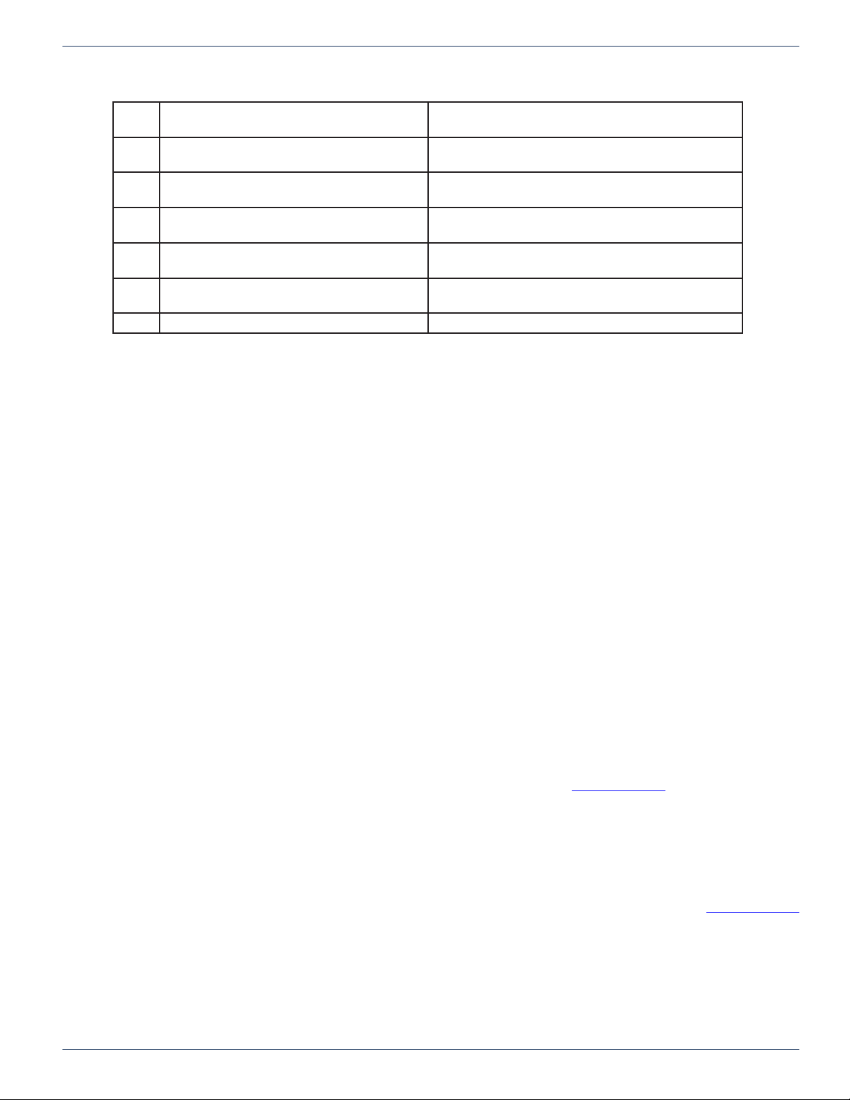
The control in port of the MCP 128 is user congurable and is used for serial data control of the system. The pin denitions
are listed in the table below.
Pin Control In - RS 232 mode Control In - RS 422/485 mode
1 GND GND
2 TXD
(transmit data)
FLEXNET – FNER Expandable (Modular) Routing Switches – Installation & Operation Manual 2-1
Not used
Page 8
CHAPTER 2: CONNECTIONS & PROTOCOLS
3 RXD
(receive data)
4 DTR
(data terminal ready)
5 GND
(signal gound)
6 DSR
(data set ready)
7 CTS
(clear to send)
8 RTS
(request to send)
9 Not used Inverting Receive
Table 1: 8x1 Control Module Control In Port Pin Denitions
Non-inverting Transmit
Non-inverting Receive
GND
Inverting Transmit
Not used
Not used
2.4 MPC 128 Control In Port Connection
If you are using a computer to control the FNER, you can use a direct serial connection to the Control In port. For serial control,
connect a serial cable (RS-232 or RS-422/485) from the computer to the 9-pin SERIAL port on the rear panel of the MPC 128.
The connector is shared for both RS-232 and RS-422/485. Do NOT use a NULL MODEM adapter or crossover cable. Use a
straight through 1 to 1 cable.
2.4.1 MPC 128 Control In Serial Communication Settings
The serial port parameters are the same whether you are using RS-232, RS-422 or RS-485. The parameters are xed at 9600
baud, 8 data bits, no parity, and 1 stop bit (8N1). The command protocol for controlling the switch is provided in the appendix.
2.4.2 MPC 128 Control In RS-232 Description
RS-232 was designed for communication of local devices, and supports one transmitter and one receiver. This standard
uses single ended signals over unbalanced, unterminated wires. Single ended means the signal is sent over one wire with
respect to a single ground source. Unterminated means the signal lines do not have impedance matching at the line ends. This
interface is useful for point-to-point communication at slow speeds and over short lengths of cable. Most PCs come equipped
with one or more RS-232 serial ports.
2.4.3 RS-232 Advantages/Disadvantages
RS-232 is easy to implement and has been standardized and accepted for years. Due to the nature of RS-232, the signals are
susceptible to noise and grounding problems. These problems set a limit to cable lengths. Quintech recommends if using RS232 that the cable length be limited to 20 meters or approximately 60 feet. RS-232 is also only point-to-point communications
so only two devices will typically communicate with each other over the RS-232 standard.
2.4.4 MPC 128 Control In RS-422 Description
In RS-422 communications, a pair of twisted wires is used to carry a signal. The data is encoded and decoded as a differential
voltage between the two lines. As a differential voltage, in principle the interface is unaffected by differences in ground voltage
between sender and receiver. For more details on differential signaling, refer to the “RS-485” section of this document.
2.4.5 RS-422 Advantages/Disadvantages
RS-422 differential signals over twisted pair wires are less affected by noise. They therefore can communicate at faster rates
and over longer distances. RS-422 is better than RS-232 but it still is limited to one master and up to ten receivers on the bus.
Recommended maximum length is 4000 feet. The FLEXNET RS-422 standard is limited to 10 receivers.
2.4.6 MPC 128 Control In RS-485 Description
The MPC 128 can be congured to communicate in RS-485 standard. For all RS-485 information, refer to the “RS-485” section
of this document.
2.4.7 All Control Port Connections except MPC Control In
Before powering up the units, make sure all of the control cables are properly installed. All FNER modules should be daisy-
chained together, with the MPC 128 unit occupying the rst position in the chain. Connect the CONTROL OUT port of the
MPC 128 to the CONTROL IN port of the rst 16x1 module in the chain. The CONTROL OUT port of that module connects to
the CONTROL IN port of the next 16x1 module, etc. The last module in the chain will have an unused 9-pin connector labeled
CONTROL OUT.
2-2 FLEXNET – FNER Expandable (Modular) Routing Switches – Installation & Operation Manual
Page 9
Note that the maximum control cable length that can exist between FNER modules is 6 feet. Refer to the appendix for proper
control port conections.
2.5 Ethernet Port
The MPC 128 has the ability to communicate over Ethernet. The system has a 10BaseT or 100BaseT Ethernet port
depending on options ordered. The Ethernet port supports a Telnet interface, TCP/IP and SNMP. All commands are sent to
the congured IP address and port. The command protocol for controlling the switch is provided in Appendix D.
2.5.1 Ethernet Connections
For Ethernet connections, connect the MPC 128 to a network port or router via the Ethernet port using a standard cable.
You can also connect directly to the computer’s network port, but this requires a crossover cable. Standard and crossover
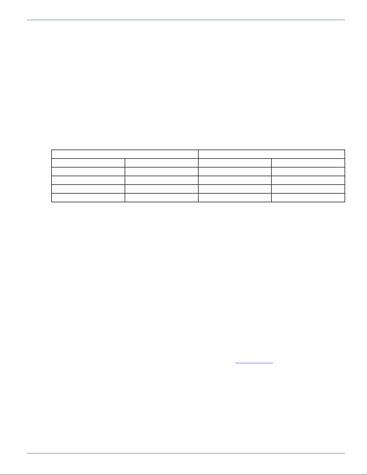
Ethernet cable pinouts are provided in Table 2: Ethernet Cable Pinout.
2.5.2 Ethernet Cable Pinout
Crossover Cable Standard Cable
RJ-45 RJ-45 RJ-45 RJ-45
Pin 1 Tx + Pin 3 Rx + Pin 1 Tx + Pin 1 Rx +
Pin 2 Tx - Pin 6 Rx - Pin 2 Tx - Pin 2 Rx -
Pin 3 Rx + Pin 1 Tx + Pin 3 Rx + Pin 3 Tx +
Pin 6 Rx - Pin 2 Tx - Pin 6 Rx - Pin 6 Tx -
CHAPTER 2: CONNECTIONS & PROTOCOLS
2.6 Ethernet Command Protocol
2.6.1 TCP/IP
The same command protocol is used for control over Ethernet TCP/IP and the serial port. Since the same command formats
are used, the command packet will contain a serial address. This address must match the serial address of the MPC 128 or
the packet will be rejected, even though the address is unnecessary when the command is sent over TCP/IP. To avoid any
problems, commands sent over TCP/IP should use the broadcast address “FF” hexadecimal.
2.6.2 Telnet
A Telnet console window is also provided for conguring and controlling the matrix. A command mode is provided where the
same protocol commands can be issued but no serial address or packet headers are required. See Appendix D for more
information.
2.6.3 SNMP
SNMP or Simple Network Management Protocol is now implemented on all MPC 128s. It is part of the Transmission Control
Protocol/Internet Protocol (TCP/IP) protocol suite. The Simple Network Management Protocol (SNMP) is an application layer
protocol that facilitates the exchange of management information between network devices.
SNMP works by sending messages, called protocol data units (PDUs), to different parts of a network. SNMP-compliant
devices, called agents, store data about themselves in Management Information Bases and return this data to the SNMP
requesters.
To use the protocol it has to be turned on from the front keypad rst. Refer to “SNMP” section.
Table 2: Ethernet Cable Pinout
FLEXNET – FNER Expandable (Modular) Routing Switches – Installation & Operation Manual 2-3
Page 10

CHAPTER 2: CONNECTIONS & PROTOCOLS
This page left intentionally blank.
2-4 FLEXNET – FNER Expandable (Modular) Routing Switches – Installation & Operation Manual
Page 11
FRONT PANEL BASICS
3. Front Panel Basics
3.1 Front Panel Interface
The front panel keypad and screen are used to set various operating parameters and to monitor and control the FNER
Switch. Various sub-menu screens appear on the front panel LCD.
3.2 Main Menu
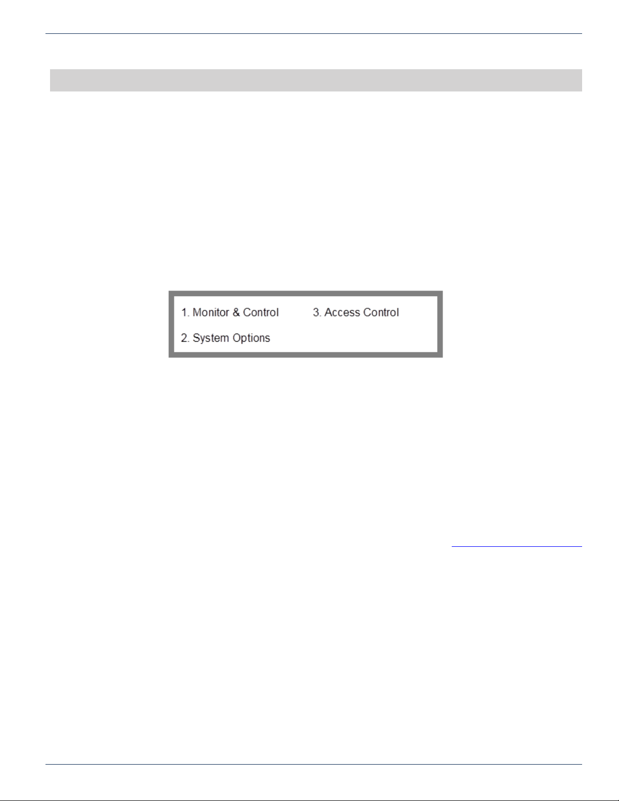
The Main Menu has three choices, “Monitor & Control”, “System Options”, and “Access Control”.
When in any other menu, pressing F4 repeatedly will exit you out of a screen back to the previous screen. Pressing F4
repeatedly will get you back to the Main Menu as shown in Figure 3. There is one exception, the download rmware screen
can only be exited by downloading rmware or power cycling the MPC 128. This main menu is the top of the front panel
hierarchy.
CHAPTER 3: FRONT PANEL BASICS
Figure 3: Main Menu
3.3 Front Panel Hierarchy & Page References
The entire front panel hierarchy is listed below. The page number that refers to a particular menu item is listed here for your
convenience. Some options are only available if logged in as the Admin.
1. Monitor & Control………………………………………….………..………….31
2. System Options Menu…………………………………………….…………..…39
2.1. Conguration Menu…………………………………………………...40
Entry into the conguration menu requires a factory code. The code is 732. Refer to section “Factory Settings Code Number”
for more information on this code. Most settings under this menu are critical to system functionality. Care should be taken
any time this menu is accessed.
2.1.1. System Setup Menu.………………………………………...42
2.1.1.1. Matrix Size………………………………………...43
2.1.1.2. Model……………………………………………...44
2.1.1.3. Module Sizes Menu…………………….…………45
2.1.1.3.1. SRR Module Size……………………….46
2.1.1.3.2. SRO Module Size……………………….47
2.1.2. Load Firmware……………………………………………… 48
FLEXNET – FNER Expandable (Modular) Routing Switches – Installation & Operation Manual 3-1
Page 12

CHAPTER 3: FRONT PANEL BASICS
2.1.3. Features Menu………………………….…………………... 54
2.1.3.1. Set Control Mode…………………….…………....55
2.1.3.2. Options Menu…….……………………………….56
2.1.3.2.2. LNB/SNMP menu………..LNB option not available
2.1.3.2.2. SNMP Menu.…………………………….57
2.1.3.2.2.1. SNMP On/Off………………….58
2.1.3.2.2.2. Set SNMP Trap IP….…..……...59
2.1.3.3. Port Access Control Enable/Disable………………62
The rest of the front panel hierarchy does not require the “732” factory settings code number to make changes to the system.
2.2. Interface Options Menu…………….…………..…….……….……....22
2.2.1. Serial Interface Menu………………………………………. 22
2.2.1.1. Set Address………………………...……………...23
2.2.1.2 Mode………………………………………………24
2.2.1.3. RS-485 Termination ………………………………25
2.2.2. Ethernet Conguration Menu……………………………….25
2.2.2.1. Static IP Conguration……………………………26
2.2.2.2. DHCP On/Off……………………………….…….27
2.2.2.3. QEC Port/Password Menu………………………...28
2.2.2.3.1. QEC Port #………………………………29
2.2.2.3.2. Reset Password………………………….30
3. Access Control Menu……………………………………………………………63
3.1. Keypad Lock………………………………………………………….64
3.2. Login/Logout…………………………………………………….…….66
3.3. Access Control Setup Menu…….……………..………………………68
3.3.1. Set Users…………………………………………………. 69
3.3.2. Set Access…………………………………………………… 71
3-2 FLEXNET – FNER Expandable (Modular) Routing Switches – Installation & Operation Manual
Page 13
CHAPTER 4: INITIALIZING SYSTEM FROM THE KEYPAD
INITIALIZING SYSTEM FROM THE KEYPAD
4. Initializing System from the Keypad
4.1 Communications Setup
If the MPC 128 is to be controlled by a port connection in addition to the keypad, the communication parameters must be set
up rst.
4.1.1 Interface Options Menu
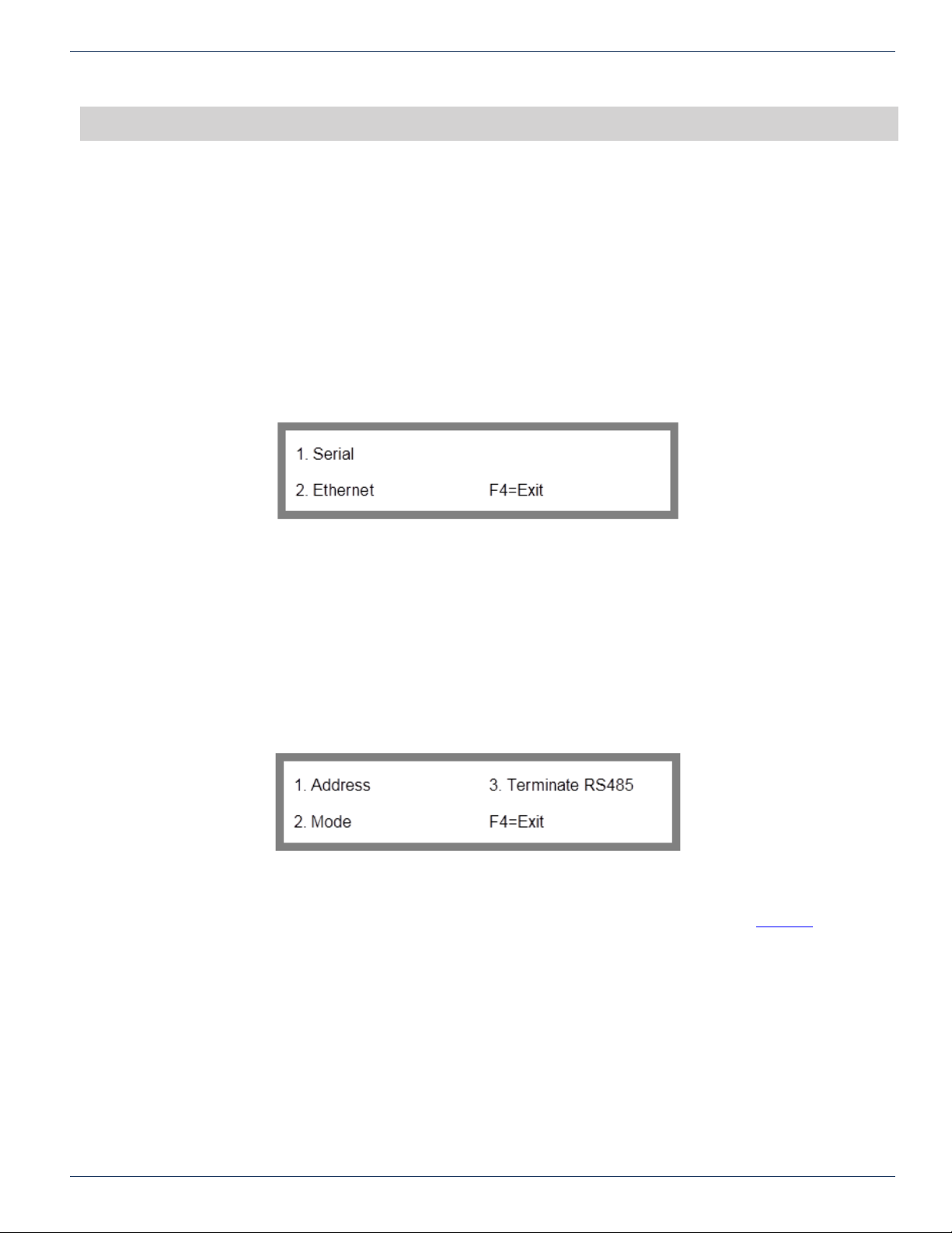
Option 2 of the System Options Menu will load the Interface Options Menu screen shown in Figure 4.
To get to the Interface Options Menu from the main menu: key sequence 2, 2.
2. System Options
2. Interface Options
4.2 Serial Interface Menu
If you are going to connect up to the Control In serial port to control the matrix you have to set up the serial port for proper
communications protocol.
Option 1 Serial of the Interface Options Menu will load Serial Interface Menu screen shown in Figure 5: Serial Interface Menu.
To get to the Serial Interface Menu screen from the main menu: key sequence 2, 2, 1.
2. System Options
2. Interface Options
1. Serial
From this screen, you will be able to congure both the address of the MPC 128 and the type of serial interface you will be
using, (RS-232, RS-422, or RS-485). For information on option 3 Terminate RS-485, refer to section “RS-485”.
4.2.1 Address
Option 1 of the Serial Interface Menu opens the Serial Address screen shown in Figure 6. The Serial Address screen
allows you to set a 2-byte hexadecimal address for the MPC 128. This address is used by the FLEXNET software to
communicate properly to the serial port. Set the address for the MPC 128 and then when setting up the parameters for serial
communications in the FLEXNET software, set the address to the same address as the MPC 128.
Figure 4: Interface Options Menu
Figure 5: Serial Interface Menu
4.2.2 Valid Addresses
Addresses can be set from 00 to FE hexadecimal. The unit only responds to commands sent over the serial bus that contain a
matching address. The only exception is the address “FF” which is a broadcast address. All units will respond to a command
containing FF as the address regardless of its current address. For this reason, FF should not normally be used as a unit
address.
FLEXNET – FNER Expandable (Modular) Routing Switches – Installation & Operation Manual 4-1
Page 14

CHAPTER 4: INITIALIZING SYSTEM FROM THE KEYPAD
4.2.3 Set Address
Get to the Serial Address screen on the front panel. The screen will look like Figure 6.
To get to the Serial Address screen from the main menu: key sequence 2, 2, 1, 1.
2. System Options
2. Interface Options
1. Serial
1. Address
To change the address, use the up and down arrows until the desired address is displayed, then press F1 to select the new
address. No change is made until the F1 key is pressed. The address range is from 00H to FEH. Do not use FFH as an
address. Press F4 repeatedly to back out to the main menu again.
4.2.4 Mode
Option 2 of the Serial Interface Menu opens the Mode screen of Figure 7.
To get to the Mode screen from the main menu: key sequence 2, 2, 1, 2.
2. System Options
2. Interface Options
1. Serial
2. Mode
Figure 6: Serial Address
The Mode screen enables you to specify whether an RS-232, RS-485, or RS-422 serial interface will be used to communicate
with the Control In serial communications port. Select the appropriate protocol and back out by pressing F4.
4.2.5 RS-485 Termination
Option 3 of the Serial Interface Menu opens the RS-485 Termination screen shown in Figure 8.
To get to the RS-485 Termination screen from the main menu: key sequence 2, 2, 1, 3.
2. System Options
2. Interface Options
1. Serial
3. Terminate RS-485
This screen enables you to specify how the Control In port is terminated. This setup is only necessary if you are using RS485 communications on the port. If you are not using RS-485 communications then these settings should be turned off. There
is an entire section of this manual that explains the details of RS-485 termination. Refer to section “RS-485” for assistance
Figure 7: Mode
Figure 8: RS-485 Termination
4-2 FLEXNET – FNER Expandable (Modular) Routing Switches – Installation & Operation Manual
Page 15
on this subject. Ignore the remote termination settings. They have no effect on operation.
4.3 Ethernet Conguration Menu
If you are going to use the Ethernet port to control the matrix, you have to set up the Ethernet port for proper communications
protocols and settings.
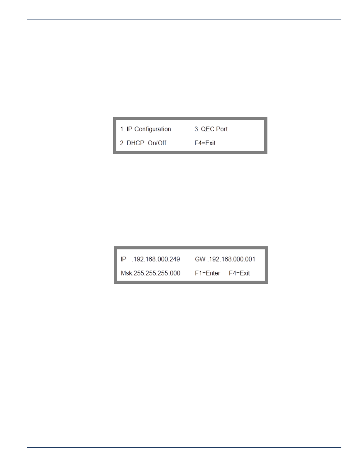
Option 2 of the Interface Options Menu will load the Ethernet Conguration Menu screen shown in Figure 9.
To get to the Ethernet Conguration Menu from the main menu: key sequence 2, 2, 2.
2. System Options
2. Interface Options
2. Ethernet
4.3.1 Static IP Conguration
Option 1 of the Ethernet Conguration Menu will load the Static IP Conguration screen shown in Figure 10. This screen
allows the user to set the static IP address, gateway and mask for the MPC 128. Contact your network administrator for the
correct values to use for these parameters.
To get to the Static IP Conguration screen from the main menu: key sequence 2, 2, 2, 1.
2. System Options
2. Interface Options
2. Ethernet
1. IP Conguration
CHAPTER 4: INITIALIZING SYSTEM FROM THE KEYPAD
Figure 9: Ethernet Conguration Menu
Figure 10: Static IP Conguration
The information displayed on the IP conguration screen depends on the DHCP setting. Whether or not you can change the
conguration also depends on the DHCP setting. Changes are only made after pressing F1. F4 will back you out without
making any changes to the settings.
4.3.2 IP Conguration Display with DHCP Off
If DHCP is off then the currently congured static IP information will be displayed. When DHCP is off the IP address, the
gateway, and the mask can be changed.
4.3.3 IP Conguration Display with DHCP On
If DHCP is on and the MPC 128 has successfully been assigned an address from the DHCP server, then that current
information is displayed on the screen. If DHCP is on but for some reason a DHCP server could not be found for addressing,
then the static conguration will be displayed. In this case, you can change the IP conguration even if the DHCP is on.
4.4 DHCP On/Off
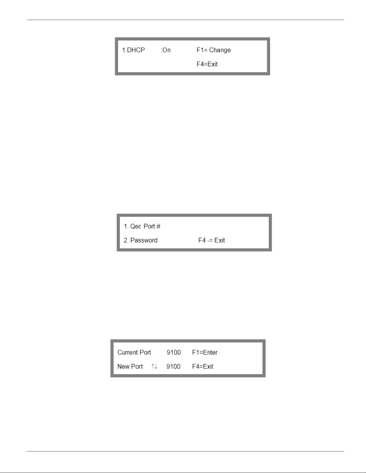
Option 2 of the Ethernet Conguration Menu will load the DHCP On/Off screen shown in Figure 11.
To get to the DHCP On/Off screen from the main menu: key sequence 2, 2, 2, 2.
2. System Options
2. Interface Options
2. Ethernet
2. DHCP On/Off
FLEXNET – FNER Expandable (Modular) Routing Switches – Installation & Operation Manual 4-3
Page 16
CHAPTER 4: INITIALIZING SYSTEM FROM THE KEYPAD
This screen allows you to enable or disable DHCP service. This will cause the MPC 128 to look for a DHCP server to assign
an address for network communications after boot up. Pressing F1 turns DHCP on/off.
4.4.1 Should DHCP be On or Off?
When set to ON, the IP address of the MPC 128 is dynamically assigned by the DHCP server. Note that the IP address
assigned in this manner will override any IP address that may have been specied via the Static IP conguration screen.
When set to OFF, the static IP address that is specied in the IP conguration screen will be used. Contact your network
administrator to conrm the correct setting of DHCP service.
4.5 COMM Port/Password Menu
Option 3 of Ethernet Conguration Menu loads the COMM Port/Password Menu shown in Figure 12.
To get to the COMM Port/Password Menu from the main menu: key sequence 2, 2, 2, 3.
2. System Options
2. Interface Options
2. Ethernet
3. Qec Port
Figure 11: DHCP On/Off
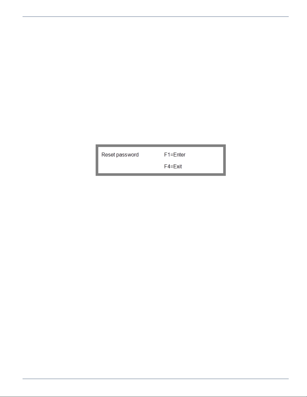
Option 1 will load the COMM port# screen shown in Figure 13.
To get to the COMM Port# screen from the main menu: key sequence 2, 2, 2, 3, 1.
2. System Options
2. Interface Options
2. Ethernet
3. Qec Port
1. Qec Port #
4.5.1 COMM Port Number
The Set COMM port # screen allows you to congure the port number for the COMM port access. Contact your network
administrator for the correct values to use for this parameter. Use the scroll keys to scroll the port number up or down until
the desired port number is displayed or type in the port number. Press F4 to exit or F1 to change the port number.
Figure 12: COMM Port/Password Menu
Figure 13: COMM Port #
4.5.2 What is a COMM Port Number?
A port number represents an endpoint or “channel” for network communications. Port numbers allow different applications on
the same computer to utilize network resources without interfering with each other. Port numbers most commonly appear in
4-4 FLEXNET – FNER Expandable (Modular) Routing Switches – Installation & Operation Manual
Page 17
network programming, particularly socket programming.
4.5.3 COMM Port Number Default Setting
The default setting of the COMM port is 9100. This number was selected because it is a port number that is not widely used
or registered by IANA (Internet Assigned Numbers Authority). Most applications use much lower numbers like 1000 or less.
4.5.4 Why Change the COMM Port Number?
In almost all cases, there is not a conict and the port number will be left at the default of 9100. In case your network happens
to be using port # 9100 for some reason, you can change FNER’s port number to some other value to avoid communication
conicts.
4.5.5 Reset Password
Option 2 will load the Reset Password screen shown in Figure 14.
To get to the Reset Password screen from the main menu: key sequence 2, 2, 2, 3, 2
2. System Options
2. Interface Options
2. Ethernet
3. Qec Port
2. Password
CHAPTER 4: INITIALIZING SYSTEM FROM THE KEYPAD
The Reset Password screen enables you to reset the COMM port access password to the FLEXNET-specied default. Press
F4 to exit or F1 to reset the password.
4.5.6 Why Reset the Password?
The password can be set with the ELP command from a communication port on the MPC 128. You can nd more information
about this in the FNER protocol document found in the appendix.
This ELP command allows the user to use almost any ASCII hex values to set the password. The user can even use ASCII
hex values that are not found on a standard keyboard. If the password is accidentally programmed with a Hex value that can’t
be typed in from a keyboard then the password needs to be reset.
Figure 14: Reset Password
FLEXNET – FNER Expandable (Modular) Routing Switches – Installation & Operation Manual 4-5
Page 18

CHAPTER 4: INITIALIZING SYSTEM FROM THE KEYPAD
This page left intentionally blank.
4-6 FLEXNET – FNER Expandable (Modular) Routing Switches – Installation & Operation Manual
Page 19
CROSSPOINT CONNECTIONS
5. Crosspoint Connections
This part of the manual describes how to monitor and change all RF connections through the keypad interface.
5.1 Monitor a Connection
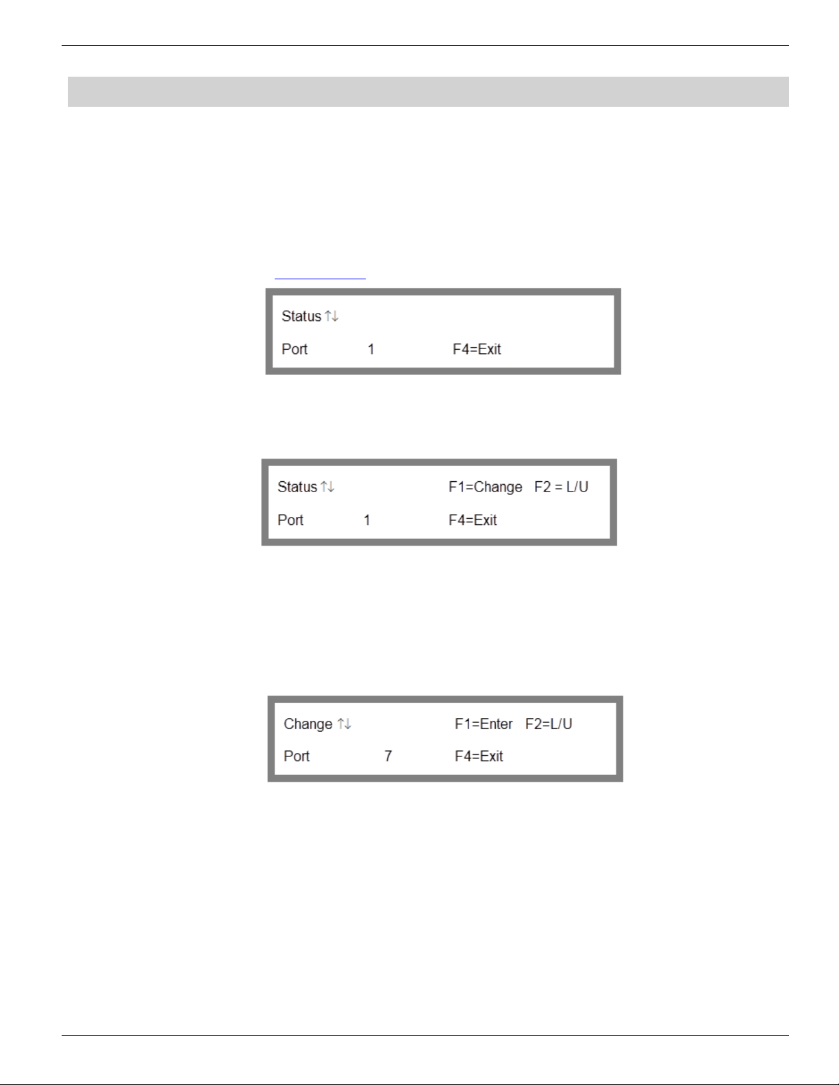
Option 1 “Monitor and Control” from the main menu will load a Connection Status screen similar to Figure 15. The screen
may have more options available if you are logged in with permissions or access control is disabled. For more information on
permissions, refer to section “Access Control“.
Figure 15: Connection Status wo/Permissions
If the user is logged on with permissions or access control for the local keypad setting is off, the Connection Status screen
will look more like Figure 16.
CHAPTER 5: CROSSPOINT CONNECTIONS
5.2 Changing a Connection
This function is available if the user is logged on with permissions or access control for the local keypad setting is off. These
permissions are discussed in the “Access Control” section of the manual. Pressing F1 will allow the user to change the input
connected to the output.
The Change Connection screen of Figure 17 is displayed when F1 is pressed on the Connection status screen. It allows you
to change the input connected to the output.
The menu heading will change from “Status” to “Change”. Select the new input by either typing it in or scrolling through the
available inputs with the arrow keys. Press F1 to enter the change. No connection will be made until you press F1. To exit
back to the main menu without making any changes press F4.
Figure 16: Connection Status w/Permissions
Figure 17: Change Connection
5.3 Locking & Unlocking Connections
This function is available if the user is logged on with permissions or access control for the local keypad setting is off.
Pressing F2 while the Connection Status screen is displayed locks/unlocks the connection status of the currently displayed
output. The Display will be as shown in Figure 18.
FLEXNET – FNER Expandable (Modular) Routing Switches – Installation & Operation Manual 5-1
Page 20

CHAPTER 5: CROSSPOINT CONNECTIONS
The F2 button operates as a toggle. Pressing it once will lock the connection as currently specied. Pressing it again disables
the lock thereby allowing changes to be made. The F1 button will have no effect upon the output’s connection status while
the lock is enabled. When an output’s connection status is locked the word “Locked” will appear to the right of the “Status ↑↓
” label as shown in Figure 18. The connection must be unlocked before any changes to the connection can be made. This
feature was added for additional protection against an accidental crosspoint connection change.
Figure 18: Connection Lock in Effect
5-2 FLEXNET – FNER Expandable (Modular) Routing Switches – Installation & Operation Manual
Page 21
RS-485
6. RS-485
6.1 Why an RS-485 Section?
In the past, there have been questions as to how to handle certain RS-485 communications setups with FNER systems. This
section was written to eliminate confusion about the FNER RS-485 communications, specically termination. This section
discusses the major points of RS-485 communications, including specic details such as signaling, cabling, pinout, and
termination settings.
6.2 RS-485 Basics
In order to discuss RS-485 lets review the basics of RS-232 for comparison. RS-232 in simplest terms is a three-wire
interface: one transmit, one receive, and one common ground. This is called an unbalanced signal.
It’s a simple protocol but because signaling is in reference to a common ground, the speed and cable lengths are severely
limited. RS-232 is typically only a few feet and usually limited to less than 20,000 bits per second. Rather slow for today’s
standards.
6.2.1 Balanced vs. Unbalanced
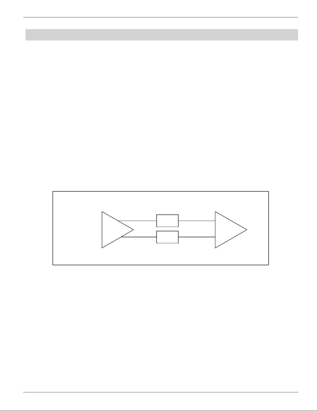
RS-485 standard uses balanced differential signals. In balanced signaling there are two lines. One signal carries the true
signal and the other carries the same signal except 180 degrees out of phase. The receiver then reads the difference
between the two signals. A basic diagram is shown in Figure 19. A ground wire does exist but it has nothing to do with how
the receiver determines the logic level of the signal.
CHAPTER 6: RS-485
Balanced Line Interface
Transmitter Receiver
6.2.2 Voltages & Signaling
A pair of wires is used to carry each signal. The data is encoded and decoded as a differential voltage between the two lines.
A typical truth table is shown below.
VA-VB < -0.2v = Logic 0
VA-VB > +0.2v= Logic 1
As a differential voltage, in principle the interface is unaffected by differences in ground voltage between sender and receiver.
6.2.3 Noise Immunity
Furthermore, if lines A and B are close together, they will be affected almost identically by external noise. If the lines are also
twisted together, then neither line is permanently closer to a noise source than the other. Hence, the well known “twisted pair”
is extremely effective in eliminating noise from the signal. Due to the nature of the differential receiver, any equivalent noise
on both wires is cancelled out.
Line A
Line B
Figure 19: Balanced Line Interface
6.2.4 Number of Devices
RS-485 standard allows 32 devices on one bus where RS-232 is typically only a one to one connection. The MPC 128 can
be on an RS-485 bus with up to and including 31 other devices.
FLEXNET – FNER Expandable (Modular) Routing Switches – Installation & Operation Manual 6-1
Page 22
CHAPTER 6: RS-485
6.2.5 Master/Slave
Most RS-485 systems use Master/Slave architecture, where each slave unit has its unique address and responds only to
packets addressed to this unit. These packets are generated by the master, which periodically polls all connected slave
units. Only communications sent to the assigned address will cause a response by the MPC 128 on the bus. This is why it is
important to assign the MPC 128 on your 485 bus a unique address.
6.2.6 4-Wire & 2-Wire Systems
RS-485 has a 2-wire and a 4-wire standard. FNER uses the 4-wire standard. This allows master to send data out one pair of
wires and the slaves sends data back to the master on the other twisted pair.
6.2.7 Cable Lengths
FLEXNET recommends the same cable length as the RS-485 standard. Your RS-485 cable length can be up to 4000 feet
between nodes.
6.2.8 Signal Reection
As data speeds and cable lengths go up, the problem of signal reections becomes important. Lines must be properly
terminated by a resistor that makes the cable look electrically like it is innitely long. An innitely long cable, of course, can
have no reected signals because the far end is innitely far away. When this reection occurs it propagates from one end of
the wires to the other end and back repeatedly. Therefore, to add something to x this reection you only need to take care
of the end of the cable, not any nodes in between the ends. When devices are daisy chained together, the MPC 128 between
the rst and last unit in the chain do not need to have termination resistors. If the MPC 128 is the last in line of a RS-485 bus
then the control termination should be on.
6.2.9 Receiver/Transmitter Termination
RS-485 termination is required to eliminate signal reection as discussed earlier. There is a twisted pair for sending data
from the PC to the MPC 128 and there is another twisted pair for the MPC 128 to transmit to the PC. Therefore, in a four
wire RS-485 bus you only need to terminate the receivers. FNER RS-485 termination therefore is only applied to the internal
receivers and not the transmitters.
6.2.10 Biasing Resistors
When an RS-485 network is an idle state, all nodes are in the receive mode and the transmitters are tri-stated. When this
happens the state of the line is undened. Bias resistors are nothing more than a pull up resistor on line B and pull down
resistor on line A to guarantee logic high when the bus is idle. When RS-485 termination is turned on these two resistors and
the termination resistor are connected to the RS-485 receiver.
6.3 Which Ports are RS-485?
The Control In port on the MPC 128 is the only RS-485 port available on an FNER system. Also to use RS-485 communications
the port has to be set up in 485 mode.
6.4 Summary
So now, we understand from the previous sections that FNER RS-485 communications only needs to terminate the ends
of the cables and we only need to terminate the receivers. Internally the MPC 128 adds a termination resistor and two bias
resistors when termination is turned on.
6.5 Front Panel RS-485 Termination
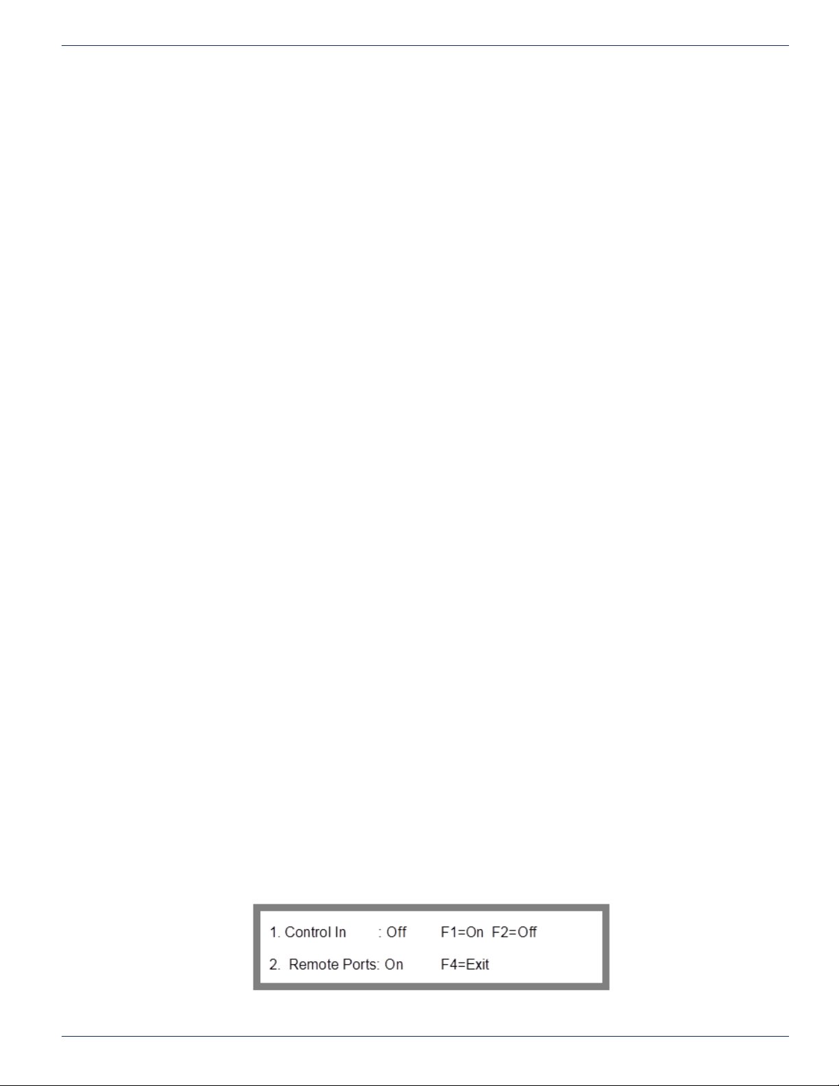
Option 3 of the Serial Interface Menu opens the RS-485 Termination screen shown in Figure 8.
To get to the RS-485 Termination screen from the main menu: key sequence 2, 2, 1, 3.
2. System Options
2. Interface Options
1. Serial
3. Terminate RS-485
Figure 20: RS-485 Termination
6-2 FLEXNET – FNER Expandable (Modular) Routing Switches – Installation & Operation Manual
Page 23

6.5.1 RS-485 Control In Port Termination
The MPC 128 Control In port can be congured for RS-485 communications. If the Control In port is congured for RS-232
communications then the Control In termination should be off. If the Control In port is congured for RS-422 or RS-485
communications and it is the last unit on the bus, then the control termination should be on. If the MPC 128 is not the last
unit on the bus then the control termination should be off. If you are not using RS-485 or RS-422 on the Control In port then
leave this setting off.
CHAPTER 6: RS-485
FLEXNET – FNER Expandable (Modular) Routing Switches – Installation & Operation Manual 6-3
Page 24

CHAPTER 6: RS-485
This page left intentionally blank.
6-4 FLEXNET – FNER Expandable (Modular) Routing Switches – Installation & Operation Manual
Page 25
FACTORY CONFIGURATION SETTINGS
7. Factory Conguration Settings
7.1 System Options Menu
The system Options menu is a critical part of the system hierarchy. From this menu, you can select options to make your
system function differently or not function at all. Here is a list of functions available in the System Options menu:
Change the Model number
Change the Model type
Change the number of inputs
Load new rmware
Set up SNMP protocol
Set up Ethernet communication
Set up serial port communications
Enable/disable access control for 4 ports
CHAPTER 7: FACTORY CONFIGURATION SETTINGS
The serial and Ethernet software settings are non critical to system functionality. These settings are determined by how you
are communicating to the MPC 128. These settings are discussed in the section “Communications Setup”.
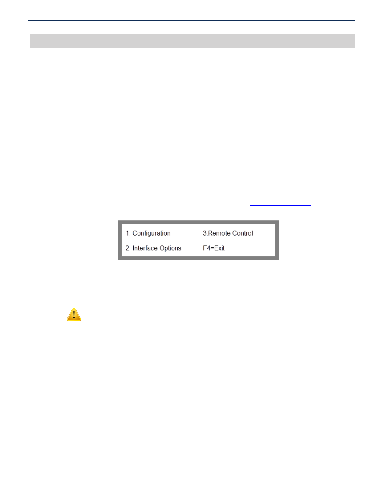
Option 2 of the Main Menu will load the System Options Menu shown in Figure 21.
2. System Options
7.2 Conguration Menu
Warning: The settings under the conguration menu are included in case of a system upgrade or
servicing. Most settings included under the conguration menu are set at the factory and should
never be changed.
Exceptions to this may be:
Adding additional modules
Enabling/disabling LNB power supplies (if equipped)
Loading new rmware
Correcting corrupted settings
System upgrade
Setting up SNMP protocol
Figure 21: System Options Menu
Option 1 of the System Options Menu will load the Conguration Menu Pass-code screen shown in Figure 22.
To get to the Conguration Menu Pass-code screen from the main menu: key sequence 2, 1
2. System Options
1. Conguration
FLEXNET – FNER Expandable (Modular) Routing Switches – Installation & Operation Manual 7-1
Page 26
CHAPTER 7: FACTORY CONFIGURATION SETTINGS
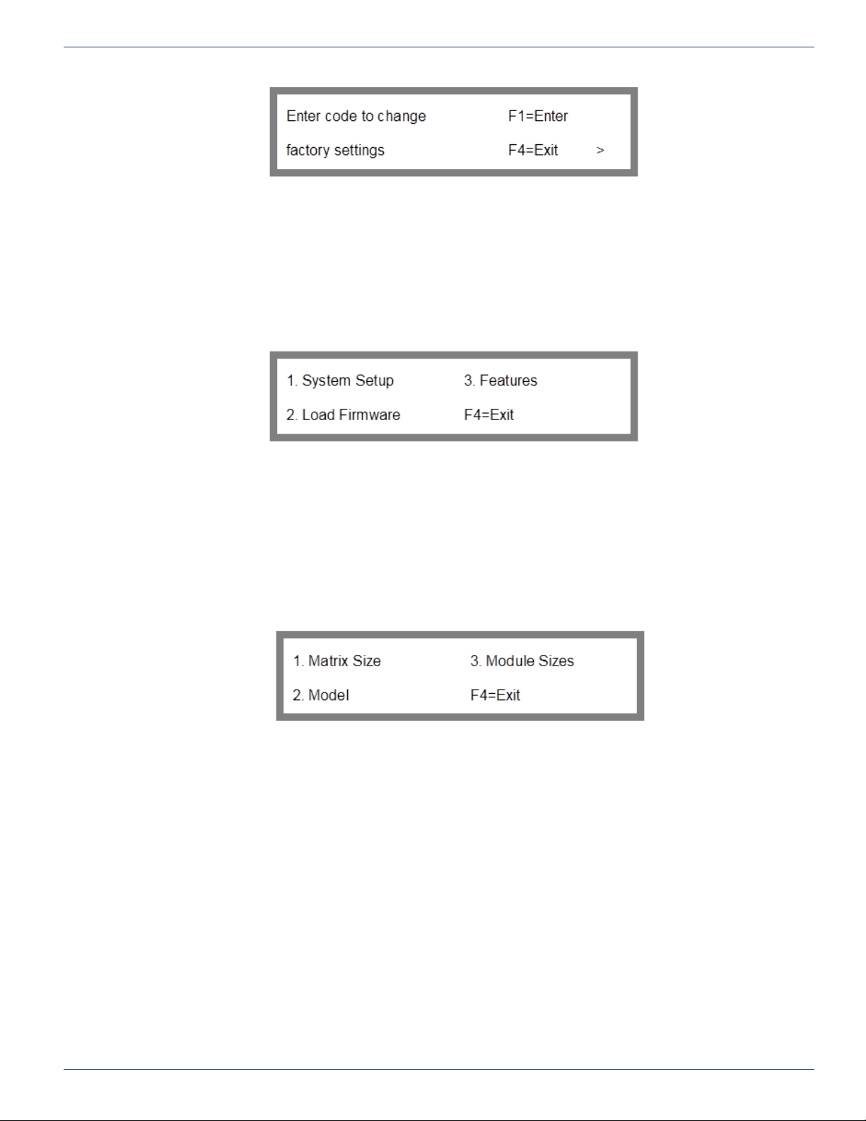
Figure 22: Conguration Menu Pass-code
7.3 Factory Settings Code Number
A code has been introduced into the front panel hierarchy in order to prevent accidental changes to the system settings. If
valid changes do need to be made to the system, the code to get into the conguration menu is 732.
This is not a security password. That is what access control is for. This number is to remind the user that they are entering
into a critical area of the menu hierarchy. If these values are improperly changed, the system will cease to operate!
To get past the password screen, simply enter the key sequence 7, 3, 2, F1. That will load the Conguration Menu screen
shown in Figure 23.
The options under the Conguration Menu are where all critical system settings can be modied.
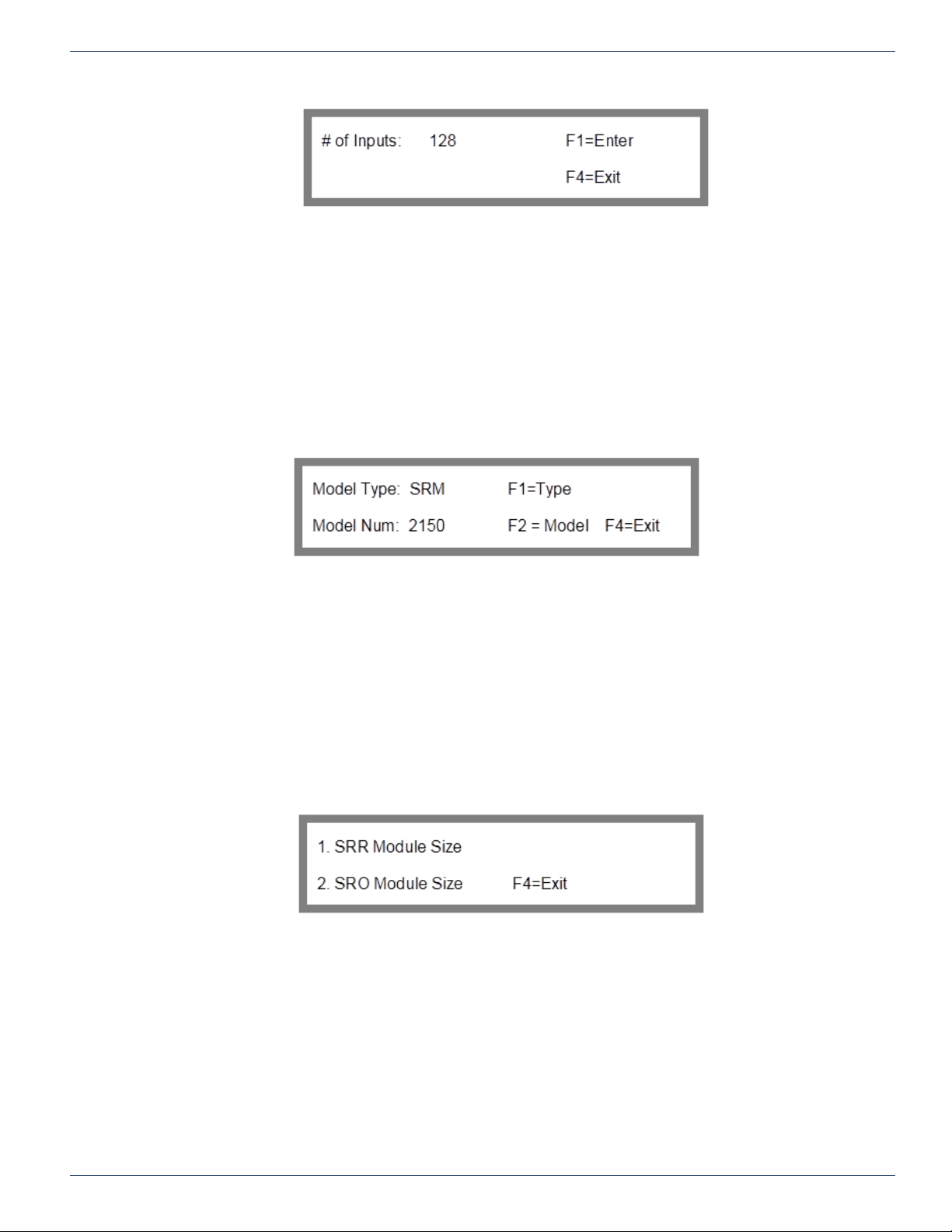
7.4 System Setup Menu
Option 1 of the Conguration Menu will load the System Setup Menu screen shown in Figure 24.
To get to the System Setup Menu screen from the main menu: key sequence 2, 1, (factory settings code number + F1), 1
2. System Options
1. Conguration (factory settings code number + F1)
1. System Setup
The system conguration of an FNER system consists of the number of matrix inputs and outputs, the model number, and
the number of SRR and SRO module outputs. The conguration settings are set at the factory and should not be changed
unless the system has been expanded with additional modules. Altering the conguration improperly will prevent the matrix
from operating correctly. We include these features to make FLEXNET factory upgrades quick and easy to implement.
7.5 Matrix Size
Option 1 of the System Setup Menu will load the Matrix Size screen of Figure 25. This option allows the specied size of the
FNER to be changed when multiple FLEXNET switch modules are used to form a larger FNER system. This setting should
never be changed unless the system is expanded with more 16x1 modules.
To get to the Matrix Size screen from the main menu: key sequence 2, 1, (factory settings code number + F1), 1, 1
2. System Options
1. Conguration (factory settings code number + F1)
1. System Setup
1. Matrix Size
Figure 23: Conguration Menu
Figure 24: System Setup Menu
7-2 FLEXNET – FNER Expandable (Modular) Routing Switches – Installation & Operation Manual
Page 27
7.6 Model
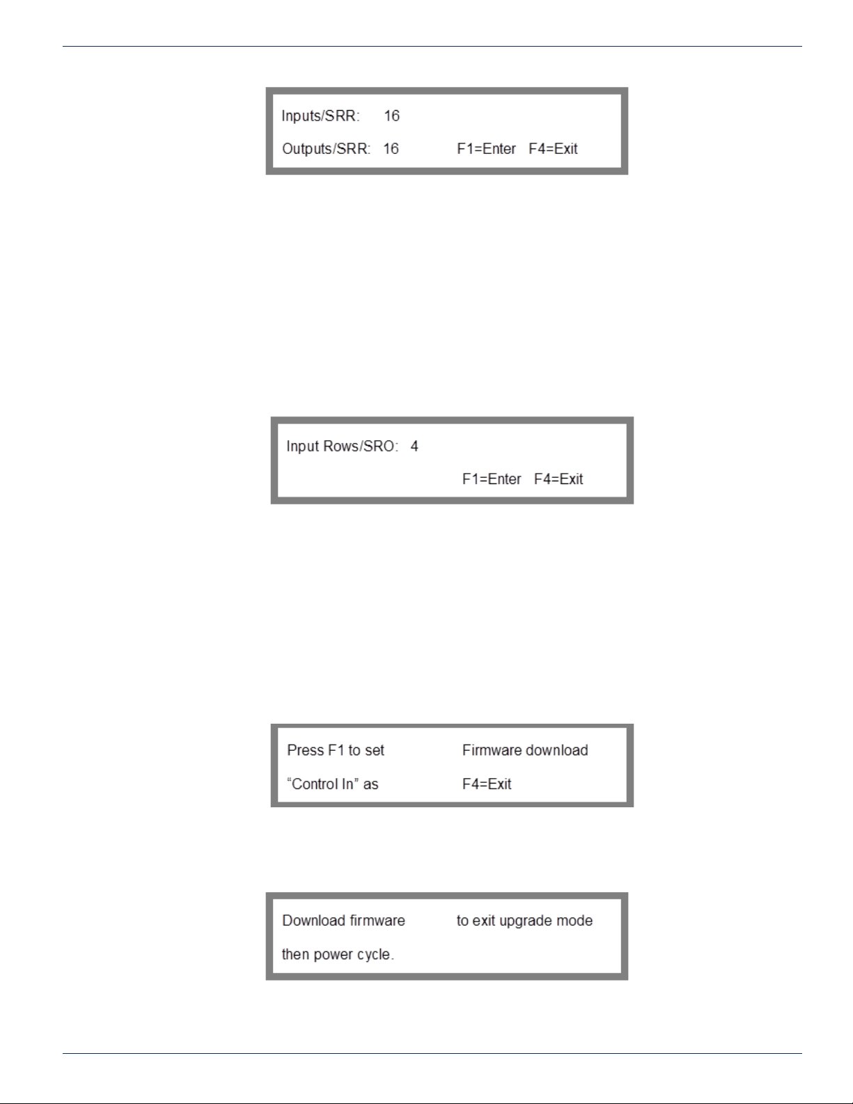
Option 2 of the System Setup menu will load the Model Number/Type screen of Figure 26. This option is included as part of
the system’s rmware identication in accordance with the protocol outlined in Appendix D. The control system is not affected
by the model number or type. System expansion requires no change of the model number.
To get to the Model Number/Type screen from the main menu: key sequence 2, 1, (factory settings code number + F1), 1, 2
2. System Options
1. Conguration (factory settings code number + F1)
1. System Setup
2. Model
CHAPTER 7: FACTORY CONFIGURATION SETTINGS
Figure 25: Matrix Size
7.6.1 Module Sizes Menu
Option 3 of the System Setup menu will load the Module Sizes Menu of Figure 27. This menu allows you to select option 1 SRR size or option 2 - SRO size. From this menu, press 1 to specify the number of inputs per SRR switching module. Press
2 to specify the number of input rows per SRO.
To get to the Module Sizes Menu from the main menu: key sequence 2, 1, (factory settings code number + F1), 1, 3
2. System Options
1. Conguration (factory settings code number + F1)
1. System Setup
3. Module Sizes
Figure 26: Model Number/Type
Figure 27: Module Sizes Menu
7.6.2 SRR Module Size
Option 1 of the Module Size Menu will load the SRR Module Size Screen of Figure 28. The standard size of an SRR is 16
inputs by 1 output, although sizes less than that can be special ordered. The maximum size that can be specied is 16 inputs
by 1 output. This setting should never be changed unless the system is being upgraded.
To get to the SRR Module Size screen from the main menu: key sequence 2, 1, (factory settings code number + F1), 1, 3, 1
2. System Options
1. Conguration (factory settings code number + F1)
1. System Setup
3. Module Sizes
1. SRR Module Size
FLEXNET – FNER Expandable (Modular) Routing Switches – Installation & Operation Manual 7-3
Page 28
CHAPTER 7: FACTORY CONFIGURATION SETTINGS
7.6.3 SRO Module Size
Option 2 of the Module Size Menu will load the SRO Module Size screen of Figure 29.
The number of input rows for each SRO output module is specied via this screen. This number should not be changed
unless the type of SRO is changed.
To get to the SRO Module Size screen from the main menu: key sequence 2, 1, (factory settings code number + F1), 1, 3, 2
2. System Options
1. Conguration (factory settings code number + F1)
1. System Setup
3. Module Sizes
2. SRO Module sizes
Figure 28: SRR Module Size
7.7 Load Firmware
Option 2 from the Conguration Menu displays the Load Firmware screen. The Load Firmware screen shown in Figure 30,
enables you to upgrade the internal rmware level of the MPC 128 unit.
To get to the Load Firmware screen from the main menu: key sequence 2, 1, (factory settings code number + F1), 2
2. System Options
1. Conguration (factory settings code number + F1)
2. Load Firmware
Pressing F1 will put the MPC 128 in a special rmware download mode. The screen shown in Figure 31 will load. Only press
F1 if you have the rmware ready for download.
Figure 29: SRO Module Size
Figure 30: Load Firmware
Figure 31: Download Firmware
7-4 FLEXNET – FNER Expandable (Modular) Routing Switches – Installation & Operation Manual
Page 29

7.8 Exiting Download Mode
If you “accidentally” put the MPC 128 in download mode, the only way get it out of this
mode is to either download the rmware or power cycle the MPC 128.
7.9 Firmware Upgrade Kit
A rmware upgrade kit only comes from ATX Networks service personel. A rmware upgrade kit will come as a zipped set of
les that will contain all the les needed to prepare and download new rmware to your MPC 128. Instructions on how to do
this procedure will be included in the zip le. Most upgrade kits include les to download from the Ethernet port or the serial
port.
7.10 Firmware Download Instructions
The instructions to download rmware are always included in an upgrade kit. There are instructions for an Ethernet download
and separate instructions for a serial port download.
7.11 Firmware Download Preparation
Write down the settings for your system before you start the download process. Record all the settings under the conguration
menu and the Interface Options menu. These setings will be overwritten during a rmware download. You will also have to
recreate any user acounts, user names, and passwords. Input – Output connections will also go back to factory defaults as
well.
A rmware download is not something that can be done in the background while the switch is operating. A rmware download
will overwrite all settings in the system. After a successsful rmware download the system settings will be set to FNER
defaults. These defaults are listed in the protocol document but listed here again for your convenience.
CHAPTER 7: FACTORY CONFIGURATION SETTINGS
7.11.1 Firmware Default Settings
DHCP Off…………………………….……..Off
Static IP…………………………………...…192.168.000.249
Static Netmask………………………………255.255.255.000
Static Gateway…………………………..….192.168.000.001
Telnet Port………………………………..… 23
QEC Ethernet Port………………..…………9100
Serial Port……………………………..…….RS-232 9600 baud 8N1
RS-485 Terminations…………………….…Off
Matrix Size……………………………………16
SRR Module Size….….…….………………16
SRO Size………..….………….…..………..…4
The crosspoint connections will also revert back to 1 to 1 connections. Input 1 connected to output 1, input 2 connected to
output 2, ect.
7.12 Ethernet or Serial Port Download?
If the rmware is downloaded from the Ethernet port the MPC 128 will reboot itself after completing the download. If the
download is done via serial port the power must be cycled manually after the download is complete. Both methods will
upgrade the mware they just use different ports and methods. If for some reason your rmware is corrupted or your Ethernet
connection is not working, you can still upgrade the rmware through the serial port. The ethernet connection connected
directly to the PC ethernet card is the easiest method.
7.13 Why Download Firmware?
New rmware is continually being developed to enhance the system features, make the system easier to use or simply add
a new feature that a customer requested. These rmware upgrades when available are not ususally nesseccary but may
enable you to have more features previously not implemented on your rmware version.
If you feel you might need to upgrade your rmware, contact ATX Networks for the latest available rmware version for your
system.
7.14 Why Is Downloading Failing?
FLEXNET – FNER Expandable (Modular) Routing Switches – Installation & Operation Manual 7-5
Page 30

CHAPTER 7: FACTORY CONFIGURATION SETTINGS
Some FLEXNET customers have encountered problems while downloading new rmware. Listed here are some of the most
common solutions to problems associated with a rmware download.
7.14.1 Serial Port Download Method Solutions
1. Use a one to one straight through serial port cable. Do not use a null modem cable or adapter.
2. Test the cable with an Ohmmeter to make sure each pin is connected to the same pin on both ends. Pin 1 connected
to only pin 1, pin 2 connected to only pin 2, ect. Test all nine pins. If there are pins that are not connected, the
download will not work.
3. Before starting the download, the MPC 128 has to be in rmware download mode as shown in Figure 31.
4. If using RS-232, check that you are connected to the Control In port
5. Copy the unzipped upgrade kit and run the applications from your root C or D drive. A directory path with more than
104 characters causes problems with some PC operating systems.
6. Make sure the COM port number in the rabbit eld utility matches the com port number you are connected to on your
PC.
7. Try bumping down the baud rate to 57600 in the RFU utility.
8. Make sure the RFU utility is pointing to the correct les:
Cold Loader = coldload.bin
Pilot BIOS = pilot.bin
Flash table = ash.ini
9. Make sure the serial port mode is congured properly (RS-232, RS-422, or RS-485).
7.14.2 Ethernet Download Method Solutions
1. If for some reason the rmware and/or Ethernet connection is no longer working you must download through the
serial port.
2. The MPC 128 does not have to be in rmware download mode to upgrade the rmware via the Ethernet port.
3. If connecting directly to a PC network card, use a cross over CAT5 Ethernet cable.
4. If you are connecting to a hub or switch, use a 1 to 1 straight through CAT5 Ethernet cable.
5. Check the cable for pinched or broken conductors. This is more common than you think.
6. Check the IP address, gateway and subnet mask of your PC. Make sure the MPC 128 gateway and mask are the
same.
An easy solution is to turn on DHCP and power cycle the MPC 128. This will allow your Ethernet DHCP server to assign the
three addresses to the MPC 128.
You can also connect to the MPC 128 directly.
These 3 addresses consist of 4 sets of numbers. These individual numbers range from 0 to 255. They are addresses that
allow the PC to nd the MPC 128 on the network. If the mask or gateway for the PC doesn’t match the MPC 128 mask and
gateway, you may be able to see the MPC 128 on the network but a rmware download will not work. Make sure the rst
three sets of numbers match the gateway.
Make sure the IP address of the unit has the rst three sets of numbers as the gateway and IP of the PC.
To nd the IP gateway and mask numbers:
Windows® 95/98:
Open a dos window
Type winipcfg
A window will be displayed that shows your PC’s conguration.
Windows NT/Me/2000/XP
Select Start > Run. Type command into the dialog box, then click OK.
In the resulting command line window, type ipcong /all.
The IP address, Subnet mask, and default gateway will be listed.
6. Copy the unzipped upgrade kit to your root C or D drive. A directory path with more than 104 characters causes
problems with some PC operating systems.
7. Make sure the Netloader.exe program can nd your MPC 128 on the network before trying to download.
8. Make sure the Netloader.exe program is pointing to the correct binary les.
Ram Loader = UDPDL2110.bin
7-6 FLEXNET – FNER Expandable (Modular) Routing Switches – Installation & Operation Manual
Page 31
User Program = *.bin under the rmware directory
7.15 Features Menu
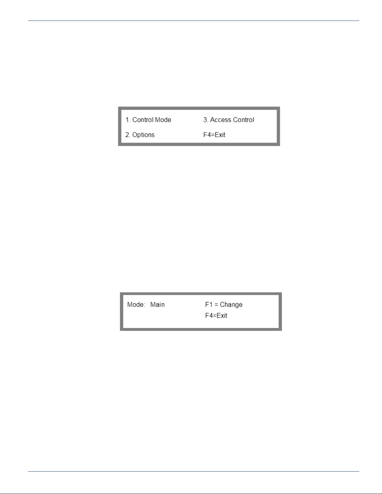
Option 3 from the Conguration menu displays the Features Menu shown in Figure 32.
To get to the Features Menu screen from the main menu: key sequence 2, 1, (factory settings code number + F1), 3
2. System Options
1. Conguration (factory settings code number + F1)
3. Features
The Features menu enables you to congure optional modes of operation for a MPC 128 module. These options include the
Control Mode, LNB Power (if equipped), SNMP protocol enabled, and to designate whether the access control system is on
or off (i.e., in effect or disabled) for various control ports.
Note: The Access Control option only appears in the Features Menu when you are logged
into the MPC 128 as Admin and access control for local is enabled. For a description of Access
Control refer to section “Access Control” on page 61.
CHAPTER 7: FACTORY CONFIGURATION SETTINGS
Figure 32: Features Menu
7.16 Set Control Mode
Option 1 of the Features Menu will load the Set Control Mode screen of Figure 33. This setting should never be changed and
should remain in main mode.
To get to the Set Control Mode screen from the main menu: key sequence 2, 1, (factory settings code number + F1) 3, 1
2. System Options
1. Conguration (factory settings code number + F1)
3. Features
1. Control Mode
Keep this setting to main.
7.17 Options Menu
Option 2 of the Features Menu will load the Options Menu screen shown in Figure 34.
To get to the Options Menu from the main menu: key sequence 2, 1, (factory settings code number + F1) 3, 2
2. System Options
1. Conguration (factory settings code number + F1)
3. Features
2. Options
Figure 33: Set Control Mode
FLEXNET – FNER Expandable (Modular) Routing Switches – Installation & Operation Manual 7-7
Page 32
CHAPTER 7: FACTORY CONFIGURATION SETTINGS
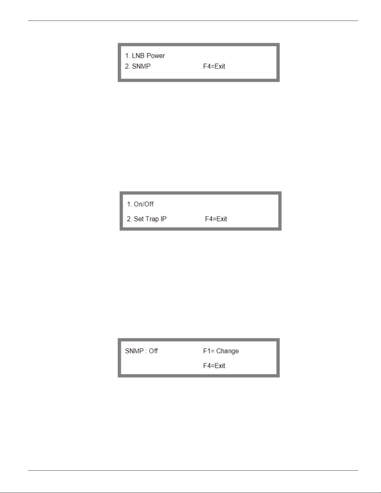
From this menu, you can select to enable/disable SNMP protocol. LNB power is not available with FNER systems. Settings
under this menu are factory preset and should not be changed.
7.18 SNMP Menu
Option 2 of the Options Menu will load the SNMP Menu shown in Figure 35.
To get to the SNMP Menu from the main menu: key sequence 2, 1, (factory settings code number + F1) 3, 2, 2
2. System Options
1. Conguration (factory settings code number + F1)
3. Features
2. Options
2. SNMP
Figure 34: Options Menu
From this menu, you can enable/disable SNMP protocol and set the Trap IP address. For details on SNMP refer to the section
“SNMP” on page 18.
7.18.1 SNMP On/Off
Option 1 of the SNMP Menu will load the SNMP On/Off screen shown in Figure 36.
To get to the SNMP On/Off screen from the main menu: key sequence 2, 1, (factory settings code number + F1) 3, 2, 2, 1
2. System Options
1. Conguration (factory settings code number + F1)
3. Features
2. Options
2. SNMP
1. On/Off
Figure 35: SNMP Menu
Figure 36: SNMP On/Off
Press F1 to toggle SNMP protocol on and off. F4 exits to the previous menu.
7.18.2 Set SNMP Trap IP
Option 2 of the SNMP Menu will load the Set SNMP Trap IP screen shown in Figure 37.
To get to the SNMP Trap IP screen from the main menu: key sequence 2, (factory settings code number + F1) 3, 2, 2, 2.
2. System Options
1. Conguration (factory settings code number + F1)
3. Features
2. Options
2. SNMP
7-8 FLEXNET – FNER Expandable (Modular) Routing Switches – Installation & Operation Manual
Page 33

2. Set Trap IP
Figure 37: Set SNMP Trap IP
7.19 Port Access Control Enable/Disable
This option is discussed in detail in the “Access Control” section of this manual.
Option 3 of the Features Menu displays the Access Control screen. Through this screen, you can designate whether the
access control system is on or off (i.e., in effect or disabled) for various control ports.
Note: The Access Control option only appears in the Features Menu when you are logged in as
the administrator. This is true regardless of whether access control has been enabled for local
control.
CHAPTER 7: FACTORY CONFIGURATION SETTINGS
FLEXNET – FNER Expandable (Modular) Routing Switches – Installation & Operation Manual 7-9
Page 34

CHAPTER 7: FACTORY CONFIGURATION SETTINGS
This page left intentionally blank.
7-10 FLEXNET – FNER Expandable (Modular) Routing Switches – Installation & Operation Manual
Page 35

ACCESS CONTROL
8. Access Control
FLEXNET denes Access control as: a means to limit the ability of people to mess things up. Our system limits a person’s
access to the system in several ways. One is the factory code needed in order to get to the conguration menu, the second
is locking the keypad, and the third is enabling access control, and creating user accounts and assigning permissions.
Access control for the FNER system is quite simple. There is only one output and 8 different accounts. Simply allow or deny
access to the output for the 8 users.
8.1 Access Control Overview
Access control for users was created for customers who had problems with unauthorized changes occurring to their switch
settings. If this is not a problem, you can simply disable access control in any combination or on all ve ports. If access
control is disabled on a communications port, than anyone using that port has the ability to change any setting or the output
connection on the FNER system.
If access control is enabled on a port the user has to login with an assigned name, assigned password, and will be pre
assigned permission to change the output connection or not.
Therefore, if access control is enabled for a port, a user can only change the output if logged in and he has permission from
the Admin to change the output.
CHAPTER 8: ACCESS CONTROL
8.2 System Access
A FLEXNET matrix is controlled by a standard Universal Control Module (MPC 128). The MPC 128 accepts control commands
from external sources that tell it how to switch the matrix or congure various system options. A standard MPC 128 has four
control ports that will accept commands:
Local: Front panel keypad and LCD.
Control In: The “PC Control In” connector. This is typically, where a control computer or PC is connected. The port can
be congured as RS-232, RS-422, or RS-485 and accepts 9600-baud 8N1 data. Command data is sent as an STX/ETX
bounded packet with checksum as dened in the protocol document.
COMM Port: Ethernet. The exact Ethernet port is user dened with the default Ethernet port set at 9100. It accepts the same
command packet that is used on the serial port. This makes it easy for a single driver to be used for both serial and Ethernet
connections.
Telnet: Telnet console window. This provides an ASCII interface with a cursor for keyboard entry of commands.
The system is highly exible and the access control feature can be congured to be on or off for each of the 4 possible control
ports on a control module.
8.3 Port Access Control Enable/Disable
Selecting “3. Access Control” at the Features Menu displays the Port Access Control Enable/Disable screen. Through this
screen, you can designate whether the access control system is on or off (i.e., in effect or disabled) for various control ports.
Note: The Access Control option only appears in the Features Menu when you are logged in as
the administrator. This is true regardless of whether access control has been enabled for local
control.
To get to the Port Access control Enable/Disable screen from the main menu: key sequence 2, 1, (factory settings code
number + F1), 3, 3
2. System Options
1. Conguration (factory settings code number + F1)
3. Features
3. Access Control
FLEXNET – FNER Expandable (Modular) Routing Switches – Installation & Operation Manual 8-1
Page 36
CHAPTER 8: ACCESS CONTROL
The ports for which access control can be on or off are as follows:
Local - Keypad
Remote - does not apply to SRX systems
Ctrl-In - PC Control In
COMM Port - Ethernet Port
Telnet - Telnet Console
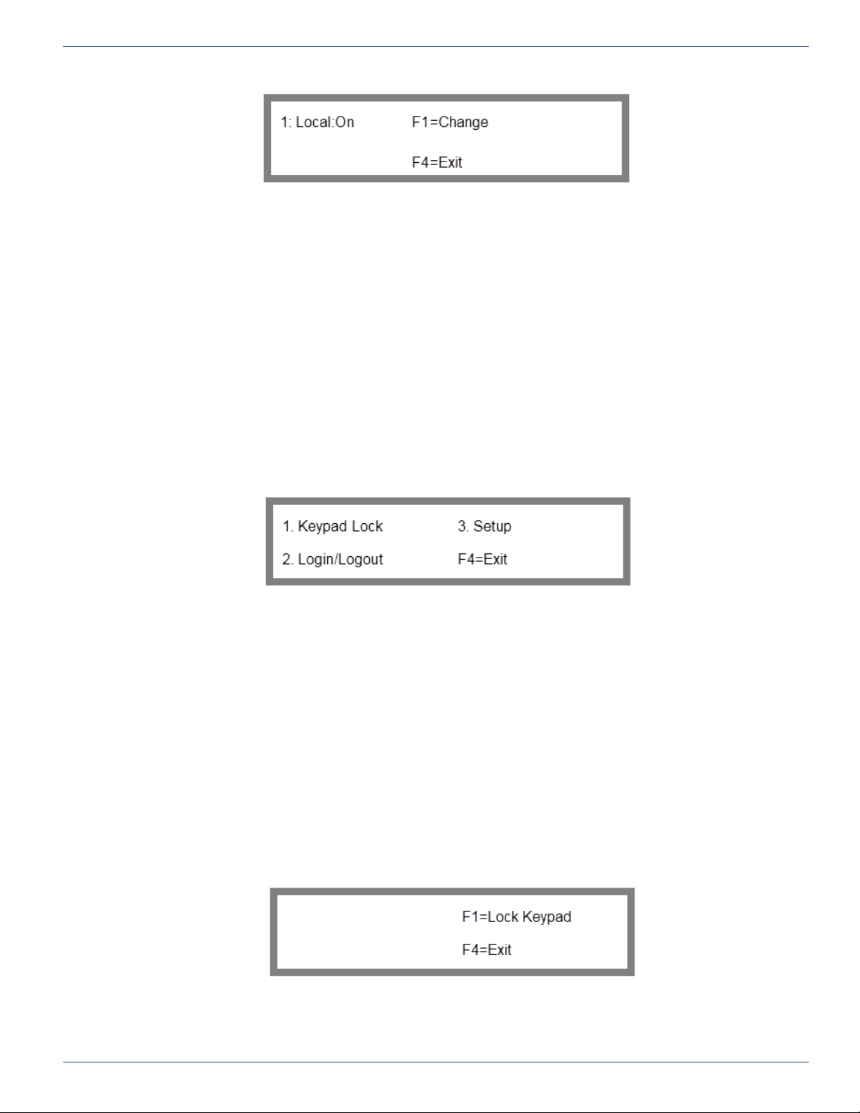
Use the up and down scroll arrows to display the port for which access control will be congured, then press the F1 key to
toggle access control on or off for that port. Press F4 to return to the Features Menu.
Once access control is enabled for a port, it will only accept passive monitoring commands unless a valid user logs in to that
port. These commands allow for passive monitoring of the matrix but do not allow changes to be made: C, F, KS, O, OS,
and Q. All other protocol commands will return with a “command unavailable” (NAK u) response. See the 2.15.06 protocol
document for more information.
Figure 38: Port Access Control Enable/Disable
8.4 Access Control Menu
Option 3 of the main menu will load the Access Control Menu screen shown in Figure 39.
From this menu, you can congure various types of access controls. From this menu, pressing 1 displays the Keypad Lock
Screen that allows you to lock or unlock access to the front panel keypad. Pressing 2 displays the Login/Logout Screen
that controls access to certain capabilities based upon the particular user access group to which a user belongs. A third
option, “Setup” will only appear when you are logged into the MPC 128 as “Admin”. It enables the administrator to dene and
congure the access capabilities for the various users. Pressing F4 returns you to the Main Menu.
8.5 Keypad Access Control
The rst and simplest part of access control is locking the keypad. This is done simply to prevent someone from bumping into
the MPC 128 keypad and accidentally changing a setting. When the keypad is locked, only the exact key sequence of 857
will allow the user back into the system from the keypad. Keypad lock does not disable any port access in any way.
8.5.1 Keypad Lock
Option 1 in the Access control menu will load the lock keypad screen shown in Figure 40.
To get to the Lock keypad screen from the main menu: key sequence 3, 1
3. Access Control
1. Keypad Lock
Figure 39: Access Control Menu
Figure 40: Lock Keypad
From the Keypad Lock Screen, press F1 to lock the keypad or press F4 to return to the Access control screen.
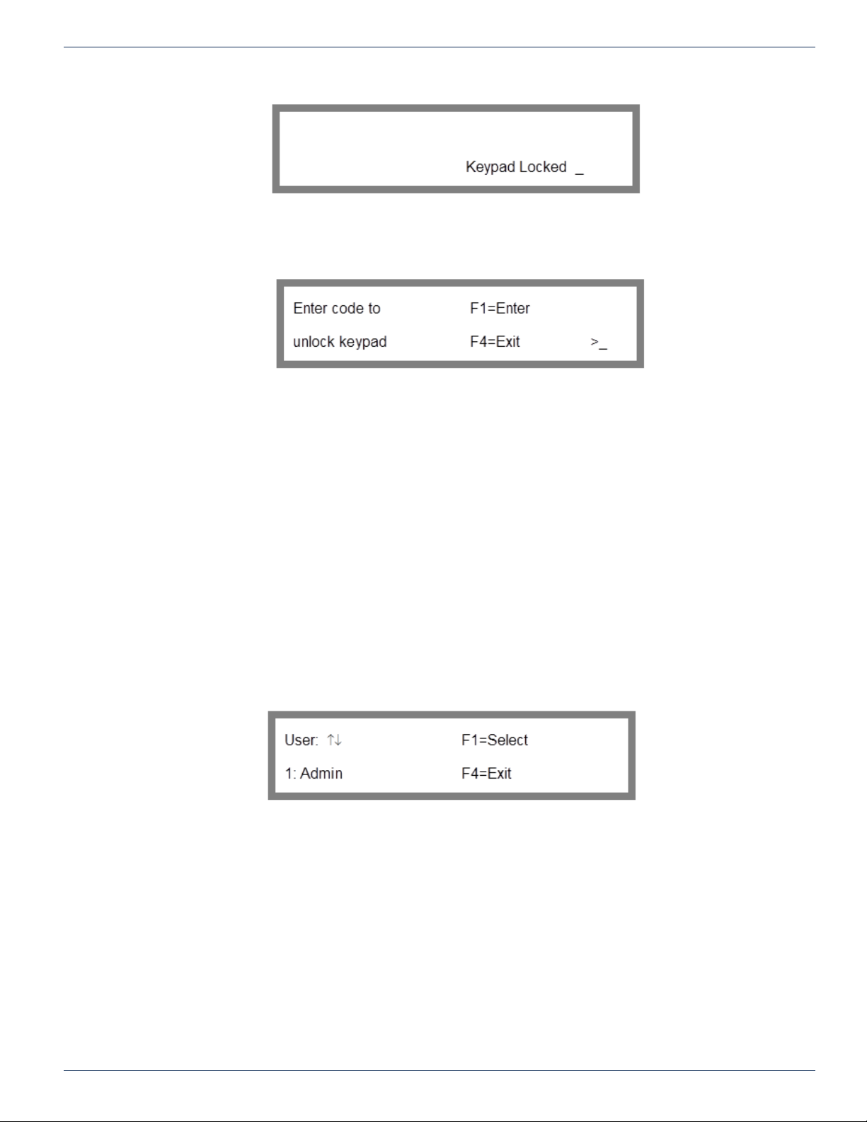
When enabled, the phrase “Keypad Locked” will be displayed on the screen to indicate that the lock is in effect. The screen
will look like Figure 41.
8-2 FLEXNET – FNER Expandable (Modular) Routing Switches – Installation & Operation Manual
Page 37
8.5.2 Unlock Keypad
To remove the keypad lock, press any key on the keypad. The Unlock Keypad Screen will be displayed shown in Figure 42.
8.5.3 Unlock Keypad Code
Enter the numeric sequence “857”. After a few seconds, you will be returned to the Keypad Lock Screen. The numeric
sequence equates to the letters “UKP” on a telephone keypad. This acronym stands for Unlock Key Pad. Entering an invalid
code or pressing the F4 key will redisplay the Keypad Locked message.
CHAPTER 8: ACCESS CONTROL
Figure 41: Keypad Locked
Figure 42: Unlock Keypad
8.6 Logging In & Logging Out
A user is automatically logged out when the MPC 128 module is reset, or if the Ethernet socket is closed or broken.
Once access control is enabled for a port then a user must login on that port before issuing any commands except those that
are allowed with no login. For the computer interface ports PC Control In, Telnet and Ethernet, the ZI protocol command is
used to login. For the Ethernet Telnet console window, any standard Telnet program may be used to bring up a text window
with a login prompt.
8.6.1 Login/Logout
To get to the Login/Logout screen from the main menu: key sequence 3, 2.
3. Access Control
2. Login/Logout
In the Login/Logout Screen 1: Admin (or the current Admin username) should be displayed. The user ID (UID) is always
displayed in front of the username since all usernames including Admin may be customized. Use the scroll keys to scroll
through the available usernames. Once the desired username is shown push F1 to select the user to log in as.
8.6.2 Password Entry
Once you have selected the desired username, the screen will change to the Password Entry screen shown in Figure 44.
Figure 43: Login /Logout
FLEXNET – FNER Expandable (Modular) Routing Switches – Installation & Operation Manual 8-3
Page 38
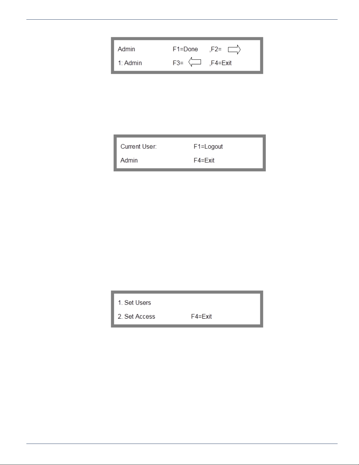
CHAPTER 8: ACCESS CONTROL
You build the password one character at a time. You can enter a number directly from the keypad or the scroll keys can be
used to bring up an alphanumeric. Once you have the correct character, push F2 to enter it and move forward to the next
character. Once all characters in the password have been entered, push F1 to attempt the login. If the password is incorrect,
the message “incorrect login” will be displayed and the password will be cleared to allow for another attempt.
8.6.3 Logout
Once the user is logged in, re-displaying the Login/Logout screen will display the current user and provide the option to
logout. The Logout Screen in Figure 45 will be displayed. To logout, press F1. Control will be returned to the Access Control
screen.
Figure 44: Password Entry
Figure 45: Logout
8.7 User Accounts
Option 3 Setup of the Access Control menu allows you to setup user accounts. User accounts consist of an assigned user
ID, a variable username and password, and permission to change the output.
User accounts can be managed remotely using the ZA, ZG, ZL, ZP, and ZU commands. See the 2.15.06 protocol document
for more information. They can also be managed from the front panel keypad.
8.8 Access Control Setup Menu
Note that you must be logged in as Admin and local access control has to be enabled to be able to access this menu.
In order to dene a user’s name, password, or permissions you need to go to the Setup screen shown in Figure 46.
To get to the Setup screen from the main menu: key sequence 3, 2.
3. Access Control
3. Setup
Figure 46: Access Control Setup
From this screen, you can select to modify user names and passwords or set output permissions.
8.9 Dening User Names & Passwords
Usernames and passwords are dened through the Set User screen.
8.9.1 Set User
To dene or modify a user name or their password, choose “Set Users” in the Setup Menu. The User Selection screen will
be displayed shown in Figure 47: User Selection.
To get to the User Selection screen from the main menu: key sequence 3, 3, 1.
3. Access Control
3. Setup
1. Set Users
8-4 FLEXNET – FNER Expandable (Modular) Routing Switches – Installation & Operation Manual
Page 39
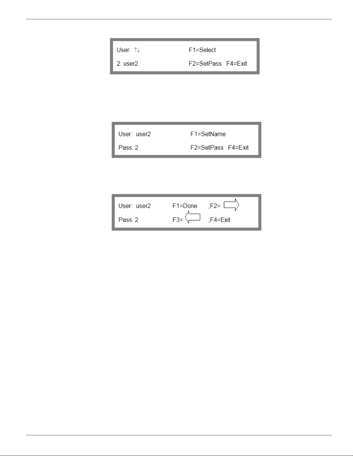
CHAPTER 8: ACCESS CONTROL
Figure 47: User Selection
In the User Selection screen, the user ID is shown followed by current username. Admin is always UID 1. You can use the
scroll keys to scroll through the available user IDs.
Use the up and down arrow keys to select the user ID whose name or password you wish to modify. As a default, the user
names “Admin” and “user2” through “user8” have already been dened when using the access control feature for the rst
time.
Once the correct user ID is selected, press F1 to enter the Select Name/Password screen shown in Figure 48.
Figure 48: Select Name/Password
To change the user name, press F1. To change the password, press F2. This will display either the Change User Name or
the Change Password screen. They are both identical except for the cursor location. The screen is shown in Figure 49.
Figure 49: Change User Name/Password
Use the F2 and F3 keys to position the cursor at a particular character position, then use the up and down arrow keys to scroll
through a list of alphanumeric characters. Repeat this process as often as necessary until the desired name or password has
been entered, then press F1 to save it and return to the Set Name/Password Screen. Pressing F4 will exit without making
any changes.
8.9.2 Valid Passwords & Length
A user name can consist of up to 14 alphanumeric characters and must begin with a letter. A password can also consist of
up to 14 alphanumeric characters and can begin with any alphanumeric character. Usernames are not allowed to start with
a number. Once the user name and password has been specied, press F1 to enter the information, then press F4 to return
to the user selection screen whereby you can choose another user whose name or password you want to change. From the
User Selection Screen, press F4 to return to the Setup Menu.
8.10 Dening Group Output Permissions
Permission for each output for each group is assigned through the Set Access menu option.
8.10.1 Set Access
The Set Access menu option in the setup directory is where Admin sets permissions for the groups.
To get to the Set Access screen from the main menu: key sequence 3, 3, 2.
3. Access Control
3. Setup
2. Set Access
FLEXNET – FNER Expandable (Modular) Routing Switches – Installation & Operation Manual 8-5
Page 40
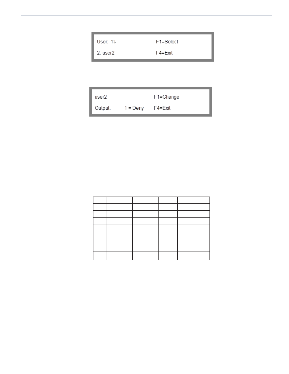
CHAPTER 8: ACCESS CONTROL
8.10.2 Setting User Access
Use the up and down arrow keys to display the name whose access capabilities you wish to modify, then press F1 to select
that group. The Set Access Screen will be displayed.
Since thee is only one output in an FNER system the Admin can only allow or deny access to the output. Press the F1 key to
display “Allow” or “Deny” for the output.
After the proper access has congured, press F4 to return to the user selection screen whereby you can choose another user
for whom you want to set access. From the User Selection Screen, press F4 to return to the Setup Menu.
Figure 50: Group Selection
Figure 51: Set Access
8.10.3 Determining Group Access
The current output access settings for a group can be found in two ways. The rst is to login as Admin on the keypad and
view the current setting in the Set Access screen. The second is to use the OS command on one the control ports. The OS
command will give the current input, whether or not the crosspoint is locked, and the current group access settings for that
output. See the 2.15.06 protocol document for more information.
8.11 Factory Defaults for Access Control
UID Username Password Group Output Control
1 Admin 1 1 All
2 User2 2 2 None
3 User3 3 3 None
4 User4 4 4 None
5 User5 5 5 None
6 User6 6 6 None
7 User7 7 7 None
8 User8 8 8 None
Table 3: Access Control Defaults
8.12 Admin Account
The Admin is the main controller of the system. He is the one who hands out and sets up all other user permissions.
8.12.1 Admin Default Login Password
The default password for the Admin is “1”. The Admin can change this password to any valid password after rst logging in
as the Admin.
8.12.2 Admin Password Warning
Current versions of the software have no reset for the Admin password. If the Admin password is programmed and then
forgotten, there are only two solutions. Reload the rmware or reset the internal board. These solutions require either qualied
ATX Networks technical service personnel or ATX Networks technical support assistance.
8-6 FLEXNET – FNER Expandable (Modular) Routing Switches – Installation & Operation Manual
Page 41
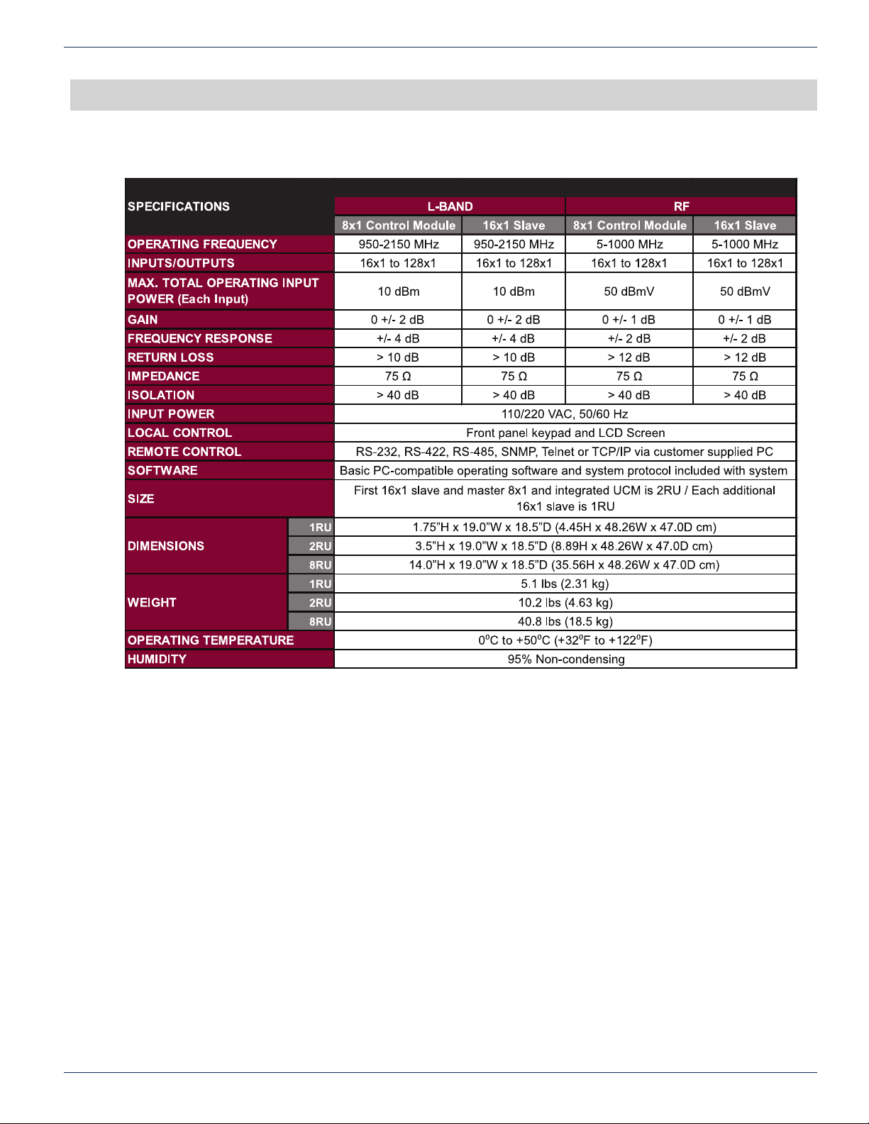
SPECIFICATIONS
9. Specications
CHAPTER 9: SPECIFICATIONS
RF Modular Routing Specications
FLEXNET – FNER Expandable (Modular) Routing Switches – Installation & Operation Manual 9-1
Page 42
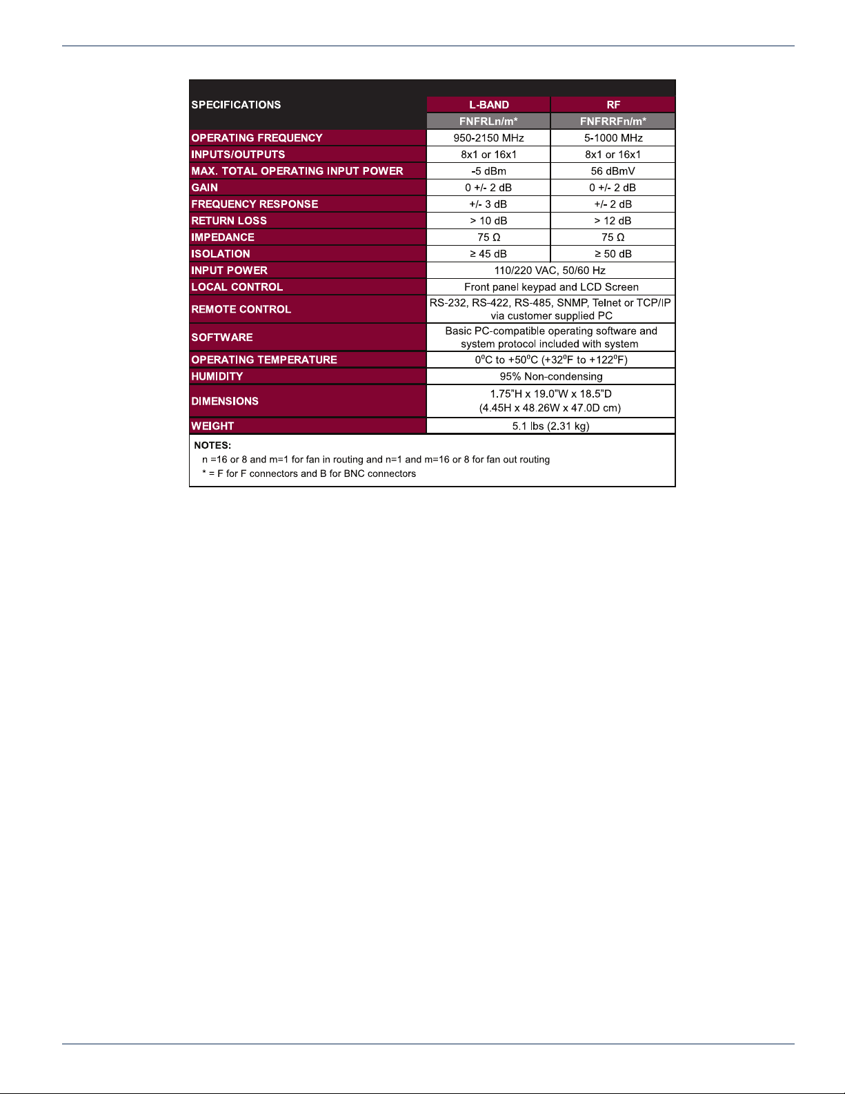
CHAPTER 9: SPECIFICATIONS
RF Fixed Routing Specications
9-2 FLEXNET – FNER Expandable (Modular) Routing Switches – Installation & Operation Manual
Page 43

SERVICE & WARRANTY
10. Service & Warranty
10.1 Contact ATX Networks
Please contact ATX Technical Support for assistance with any ATX products. Please contact ATX Customer Service to obtain
a valid RMA number for any ATX products that require service and are in or out-of-warranty before returning a failed module
to the factory.
Please have with you the following information when calling ATX Networks or include this information in an email question.
1. Model
2. Matrix Size
3. Protocol Version
4. Firmware Version
All this information is available at the front panel display when you apply power to the MPC 128.
Cycle the power of the main MPC 128, have a pencil, and paper ready. When the MPC 128 is booting up, this vital information
is briey listed on the front panel. Write down the Model, Size, protocol version, and rmware version.
CHAPTER 10: SERVICE & WARRANTY
TECHNICAL SUPPORT
Tel: (905) 428-6068
Toll Free: (800) 565-7488 (USA & Canada only)
► Press *3 for Technical Support
► Then press 1 for Digital Video Products (DVIS, DigiVu, UCrypt, etc.)
► OR, press 2 for All Other Products
CUSTOMER SERVICE
ATX Networks
1-501 Clements Road West
Ajax, ON L1S 7H4 Canada
Tel: (905) 428-6068
Toll Free: (800) 565-7488 (USA & Canada only)
► Press *1 for Customer Service
Fax: (905) 427-1964
Toll Free Fax: (866) 427-1964 (USA & Canada only)
Web: www.atxnetworks.com
Email: [email protected]
10.2 Warranty Information
All of ATX Networks’ products have a 1-year warranty that covers manufacturer’s defects or failures.
If your unit may need warranty service, having the following information ready makes a repair process easier and faster to
start and complete.
Serial number - Marked S/N on rear panel
Approximate date of purchase
FLEXNET – FNER Expandable (Modular) Routing Switches – Installation & Operation Manual 10-1
Page 44

CHAPTER 10: SERVICE & WARRANTY
This page left intentionally blank.
10-2 FLEXNET – FNER Expandable (Modular) Routing Switches – Installation & Operation Manual
Page 45
APPENDIX
11. Appendix
11.1 General Problems
The signal is lost when the power is turned off. The FNER is an active switch which requires power to maintain the
Several options referred to in the manual are
not coming up on the display.
The LCD is blank except for a row of dim blocks. Firmware has been corrupted. Contact ATX Networks for new rmware
The unit does not remember the previous
switch settings/switch size after power has
been removed and restored.
CHAPTER 11: APPENDIX
crosspoint connections. If power is turned off the signal no longer passes
through.
In order to see all the options you must be logged in as Admin and the
access control for local has to be on also.
and download instructions.
Contact ATX Networks for service.
Front Panel displays “download rmware” and it
won’t do anything
The keypad is locked Press 857
I am a qualied technician and would like to try
to x a problem myself.
11.2 Front Panel LEDs
The front panel LED is not lit. This indicates the unit is not receiving power.
You are in rmware download mode. The only solution is to download
rmware or cycle power.
1. Cycling power will not corrupt or change any settings but it will interrupt
the crosspoint connections while it reboots.
2. Downloading rmware will overwrite the entire system and set all
values back to FNER defaults. Refer to the “Load Firmware” section.
A warranty covers all units. Only ATX Networks, or a representative
of ATX Networks, should make any repairs. Removing any part of the
chassis will void the warranty. Additionally, attempting to repair a unit
could be dangerous.
1. Check to see if the power switch is in ON.
2. Make sure that the AC cables are properly connected.
3. Check the fuse located just above the power cord (if equipped).
4. Verify with a volt meter that the AC source is available. If the problem
isn’t with the AC supply, contact ATX Networks for service.
FLEXNET – FNER Expandable (Modular) Routing Switches – Installation & Operation Manual 11-1
Page 46

CHAPTER 11: APPENDIX
11.3 Problems with Crosspoint Connections
No signal is passing at all. The connection is shown as
being made but no switch occurred.
The option to change or lock/unlock a crosspoint is not
available.
The signal is passing at a low level. Using appropriate equipment, check the signal level. If it is
The monitor and control menu lists the wrong number of
inputs.
1. First, be certain that all coaxial cables are properly
connected, and that all control cables are connected and in
good working conditioning. Refer to the appendix for your
system connections.
2. Type in a different path to verify that the units are switching.
For example, if you cannot route to Input 7, try routing Input
8. Try this for several different inputs.
3. If the units are switching, verify that the signal you
requested is actually there (the system is DC blocked and
will not allow receivers to power LNBs). It is useful to monitor
the system with some type of analyzer.
4. Make sure that the matrix size is set correctly. The
actual matrix size will only switch up to the set matrix size.
Alternately, if the MPC 128 is set larger, it will show inputs
that are not physically available.
1. You are logged in as a user with assigned permissions.
The Admin has assigned permissions to your account. Your
account denys you the ability to change the output
2. Access control is on for the port and you are not logged in.
below specications, contact ATX Networks for asistance.
Someone incorrectly changed settings under the
conguration menu. Refer to the “Factory Conguration
Settings” and contact ATX Networks for technical assistance.
11.4 Serial Port Problems
The MPC 128 will not respond to protocol commands on the
Control In serial port.
1. Make sure that you are NOT using a null modem cable or
null modem adapter. Use a straight through 1 to 1 pin cable
2. If using RS-232, check that the serial cable from the
computer is connected to the Control In DB-9 connector port
on the back panel. Not the Control Out port.
3. Make sure that the address in the commands being sent
matches the serial address set for the MPC 128.
4. Make the COM port you are using on the computer
matches the COM port the matrix control software is set at.
5. Check that the serial interface mode (RS-232 or RS485/422 is correct.
6. If using RS-422/485 make sure the termination settings
are correct.
7 Make sure the data protocol is 8 bit 1 stop bit no parity and
9600bps.
11-2 FLEXNET – FNER Expandable (Modular) Routing Switches – Installation & Operation Manual
Page 47

11.5 Ethernet Problems
The MPC 128 will not connect using Telnet. 1. Make sure that another Telnet session is not currently
MPC 128 won’t accept any SNMP protocol commands. Check that SNMP is enabled. Refer to the section “SNMP”.
I can’t change anything in the IP conguration. Turn off DHCP When DHCP is on the IP conguration
CHAPTER 11: APPENDIX
open. Only one Telnet session at a time is allowed.
2. Make sure you are trying with the correct IP address.
3. Make sure you are usiung the right type cable. Straight
through or crossover.
displays the DHCP conguration assigned to the unit, not
the static IP conguration.
The MPC 128 keeps booting up to an IP address that is not
the same as the one I had entered in the IP conguration.
The MPC 128 will not respond to protocol commands on the
Ethernet Port.
Turn off DHCP. The DHCP is assigning an address to the
unit. To use the static IP conguration turn off DHCP.
1. Make sure that the serial address in the commands being
sent is either set as “FF” or matches the serial address set
for the MPC 128.
2. Make sure that the MPC 128 IP address matches the
target address used by the control computer.
3. Make sure that the mask and gateway are correctly set
for your network.
4. If the MPC 128 is connected directly to the network port
of another computer, make sure that a crossover cable is
being used.
5. If the MPC 128 is connected to a router or switch, make
sure that a standard cable is being used, that the router
detects the connection to the MPC 128, and that the router
is connected to the same network as the control computer.
6. Make sure the Ethernet lock has not been enabled using
the ELE command.
7. Make sure that the control computer is sending the
commands to port 9100.
8. Check with the administrator that no other program is
using port 9100 for Ethernet communications
I forgot my password. 1. Default passwords are listed in Table 3.
2. If the Admin has re-assigned names and passwords
contact that person for your username and password.
3. If you are the Admin and you don’t know your password,
contact ATX Networks for technical assistance.
FLEXNET – FNER Expandable (Modular) Routing Switches – Installation & Operation Manual 11-3
Page 48
CHAPTER 11: APPENDIX
I am typing in my password but it won’t let me login. 1. Passwords are case sensitive. If the Admin gave you
a password of “PasSMe” then the P,S,and M need to be
capital letters when you type it in.
2. The Admin has reassigned or changed your password
3. The unit has been given a hard reset which sets all
accounts to default permissions, names, and passwords.
Defaults are listed in Table 3: Access Control Defaults.
I have permissions but I still can’t change an output
connection.
Check if the output is Locked. Unlock the output rst before
you change the connection.
I can’t turn on/off access control Login as Admin rst. Only the Admin can turn on/off access
control for a port.
I can’t modify the user accounts or permissions Only the Admin can modify accounts. Login as the Admin.
The system won’t allow me to make crosspoint changes. 1. Log in using your assigned username and password. If
the Admin has denied you access to the output then you
can’t change the output without the Admin changing your
account rst.
2. Login as Admin
3. Turn off access control for the port you are using. (requires
Admin login)
My password to unlock the Ethernet port using the ELD
command is not working.
Reset the password from the front panel. Refer to the section
“Reset Password”.
11-4 FLEXNET – FNER Expandable (Modular) Routing Switches – Installation & Operation Manual
Page 49

CHAPTER 11: APPENDIX
This page left intentionally blank.
FLEXNET – FNER Expandable (Modular) Routing Switches – Installation & Operation Manual 11-5
Page 50

1-501 Clements Road West, Ajax, ON L1S 7H4 Canada
Tel +1 (905) 428-6068 Toll Free +1 (800) 565-7488
Fax +1 (905) 427-1964 Toll Free Fax +1 (866) 427-1964
www.atxnetworks.com [email protected]
Printed in Canada Rev. 07/15 (ANW1082)
 Loading...