

Page 1
Multichannel MPEG-2/H.264 Encoder/Multiplexer
QAM & IP Output
Installation & Operation Manual
Page 2

General Guide Notes
Manual Release Date: March 2016
Firmware Version
Some features described in this manual require the latest rmware to be installed on the DigiVu devices. Check with ATX
Networks technical support or the related support web site for your model of DigiVu for the latest release of rmware. The
rmware version installed may be found on the ‘Maintenance’ tab of the GUI. At the time of publication of this manual the most
current released rmware version is:
System 4.21-3.19-10.46
DV1HDA Card 1.3.0
DVGIGE Card 2.0-1.15
Organization of This Manual
This manual is generally organized based on the tabbed GUI with an individual chapter dedicated to describing the congurable
features of each tab. Further chapters outline activities related to the DigiVu operation such as installation, troubleshooting,
etc.
FYI: In this guide, reference to DigiVu infers DigiVu 3RU, DigiVu CD 3RU and DigiVu Mini 1RU
unless the model is specically stated. Reference to DVIS is synonymous with DigiVu as these
products run on the same rmware..
Cross Reference Hyperlink Usage
Hyperlinks are used liberally throughout the guide to assist the reader in nding related information if the reader is viewing the
Adobe PDF le directly. Hyperlinks may be identied by their blue text. Most links are to related pages within the document,
but some reference outside documents if the reader needs that additional information. The Table of Contents is entirely
hyperlinked and bookmarks are available but the bookmark feature must be turned on in your Reader application.
Symbol Usage
Throughout the manual, some symbols are used to call the readers attention to an important point. The following symbols are
in use:
NOTE: This symbol usage will call the reader’s attention to an important operation feature of the
equipment which may be safety related or an operation that may cause a service outage.
FYI: This symbol indicates that there is helpful related information available in this note or
elsewhere in the guide.
Although every effort has been taken to ensure the accuracy of this document it may be necessary, without notice, to make amendments or correct omissions.
Specications subject to change without notice.
DigiVu®, DigiVu
herein may be covered by one or more U.S. or foreign patents. DVB®, Microsoft®, Windows® , Adobe® Reader® , DOCSIS® and other non-ATX product and company names
in this manual are the property of their respective companies.
®
CD, DigiVu
®
Mini, UCrypt® and VersAtive®Pro are registered trademarks of ATX in the United States and/or other countries. Products or features contained
Page 3

TABLE OF CONTENTS
GENERAL GUIDE NOTES ....................................................ii
1. SAFETY ............................................................. 1-1
2. SYSTEM DESCRIPTION ................................................ 2-1
2.1 Chapter Contents ................................................. 2-1
2.2 Models Covered by this Guide ....................................... 2-1
2.3 The DigiVu® Encoder .............................................. 2-2
2.4 Key Features .................................................... 2-3
2.5 Simplied Block Diagrams .......................................... 2-4
2.6 Front and Rear Panels ............................................. 2-6
2.7 Card Slot Numbering .............................................. 2-7
2.8 Available Encoder Cards ........................................... 2-8
2.9 Available Input/Output Cards ........................................ 2-9
3. FIELD APPLICATIONS .................................................. 3-1
CHAPTER 1:
3.1 Chapter Contents ................................................. 3-1
3.2 Summary of Insertion Applications .................................... 3-1
3.3 Analog Channel Insertion vs Digital Channel Insertion. . . . . . . . . . . . . . . . . . . . . 3-2
3.4 QAM Insertion Without Decoding ..................................... 3-3
3.5 Insertion Into Under-utilized QAM (Add/Drop) ........................... 3-4
3.6 IP Video Content Insertion .......................................... 3-5
3.7 Local Content Back Haul Over IP .................................... 3-6
4. INSTALLATION ........................................................ 4-1
4.1 Chapter Contents ................................................. 4-1
4.2 Recommended Installation Environment ............................... 4-1
4.3 Equipment Safety Grounding ........................................ 4-1
4.4 RF Cable Sheath Grounding ........................................ 4-2
4.5 Mounting ........................................................ 4-2
4.6 Environment Considerations. . . . . . . . . . . . . . . . . . . . . . . . . . . . . . . . . . . . . . . . . 4-3
4.7 Provisioning Electrical Power ........................................ 4-3
4.8 RF Cabling ...................................................... 4-4
4.9 Audio & Video Connections ......................................... 4-4
4.10 Ethernet Network ................................................. 4-5
4.11 Installing Modules ................................................. 4-5
5. THE GUI ............................................................. 5-1
5.1 Chapter Contents ................................................. 5-1
5.2 Conguration Pages ............................................... 5-2
5.3 Minimum Computer Requirements .................................... 5-2
5.4 Connecting to the GUI ............................................. 5-2
5.5 Connecting to the Management Computer .............................. 5-4
5.6 Connecting to a Local Cable Modem .................................. 5-5
5.7 Factory Default IP Address Settings ................................... 5-8
5.8 Default Username and Password ..................................... 5-8
DigiVu® Series Multichannel MPEG-2/H.264 Encoder/Multiplexer with QAM &/or IP Output - Installation & Operation Manual iii
Page 4

CHAPTER 1:
5.9 Resetting the Username and Password ................................ 5-8
6. ENCODER SETTINGS TAB .............................................. 6-1
6.1 Chapter Contents ................................................ 6-1
6.2 SD Encoder Cards ................................................ 6-2
6.3 HD Encoder Card ................................................. 6-2
6.4 Input and Output Cards ............................................ 6-2
6.5 Encoder Settings Tab .............................................. 6-3
6.6 Encoder Conguration Quick Guide ................................... 6-4
6.7 Encoder Setting .................................................. 6-5
6.8 Input Parameters ................................................. 6-5
6.9 Output Parameters ................................................ 6-6
6.10 Program Identication .............................................. 6-8
6.11 Platform Control Buttons. . . . . . . . . . . . . . . . . . . . . . . . . . . . . . . . . . . . . . . . . . . . 6-9
7. MUX TAB ............................................................ 7-1
7.1 Chapter Contents ................................................. 7-1
7.2 MUX Settings .................................................... 7-1
7.3 Legacy STB Settings .............................................. 7-2
7.4 DVB® SI Settings ................................................. 7-2
7.5 No Video Slide Enable ............................................. 7-3
7.6 Platform Control Buttons. . . . . . . . . . . . . . . . . . . . . . . . . . . . . . . . . . . . . . . . . . . . 7-3
8. RF OUTPUT TAB ...................................................... 8-1
8.1 RF Settings ...................................................... 8-1
8.2 Platform Control Buttons. . . . . . . . . . . . . . . . . . . . . . . . . . . . . . . . . . . . . . . . . . . . 8-2
9. MAINTENANCE TAB ................................................... 9-1
9.1 Chapter Contents ................................................. 9-1
9.2 DVIS Information ................................................. 9-2
9.3 DVIS Hardware Status ............................................. 9-2
9.4 SNMP Settings ................................................... 9-2
9.5 Remote Update Server: ............................................ 9-3
9.6 Platform Control Buttons. . . . . . . . . . . . . . . . . . . . . . . . . . . . . . . . . . . . . . . . . . . . 9-3
9.7 Network Settings .................................................. 9-6
9.8 Platform Network Control Buttons .................................... 9-7
10. DEMOD & MUX SETTINGS TAB ......................................... 10-1
10.1 Chapter Contents ................................................ 10-1
10.2 Quick Guide to Demod & Mux Conguration ........................... 10-1
10.3 Demod & Mux Settings ............................................ 10-4
10.4 Demodulator Settings ............................................. 10-4
10.5 Demodulator Settings Buttons ...................................... 10-4
10.6 Add & Drop Settings .............................................. 10-5
10.7 Add & Drop Settings Buttons ....................................... 10-6
10.8 PID Display Tree ................................................. 10-7
11. IP OUTPUT TAB ...................................................... 11-1
11.1 Chapter Contents .................................................11-1
11.2 Enabling the IP Output Tab .........................................11-2
iv DigiVu® Series Multichannel MPEG-2/H.264 Encoder/Multiplexer with QAM &/or IP Output - Installation & Operation Manual
Page 5

11.3 Support for VLAN Tagging ..........................................11-3
11.4 Gigabit Ethernet Card Fundamentals ..................................11-3
11.5 Quick Guide to the Gigabit Ethernet Card ..............................11-3
11.6 IP Output Conguration ............................................11-4
11.7 Source IP Settings ................................................11-4
11.8 Destination IP Settings .............................................11-5
11.9 Protocol Settings. . . . . . . . . . . . . . . . . . . . . . . . . . . . . . . . . . . . . . . . . . . . . . . . . .11-5
11.10 VLANS Settings ..................................................11-6
11.11 GbE Port Numbering ..............................................11-7
11.12 Two VLANs Automatically Created ....................................11-7
11.13 Stream Settings ..................................................11-8
11.14 Platform Control Buttons. . . . . . . . . . . . . . . . . . . . . . . . . . . . . . . . . . . . . . . . . . . .11-9
12. FIRMWARE UPGRADE & RECOVERY .................................... 12-1
12.1 Chapter Contents ................................................ 12-1
12.2 Types of Firmware Files ........................................... 12-1
12.3 Identifying Current Firmware Version ................................. 12-2
12.4 Exporting a Conguration .......................................... 12-2
12.5 Where to Obtain Firmware Files ..................................... 12-3
12.6 Firmware Upgrade Process ........................................ 12-3
12.7 System Recovery Process ......................................... 12-5
12.8 Restore a Conguration Export ..................................... 12-7
12.9 Username & Password Reset Process. . . . . . . . . . . . . . . . . . . . . . . . . . . . . . . . 12-8
CHAPTER 1:
13. FIELD REPLACEMENTS ............................................... 13-1
13.1 Field Replacement of Realtime Clock Battery .......................... 13-1
13.2 Field Replacement of Cooling Fans .................................. 13-1
13.3 Field Replacement of Plug-in Cards ................................. 13-2
14. TROUBLESHOOTING ................................................. 14-1
14.1 Error Codes .................................................... 14-1
15. SERVICE & SUPPORT ................................................. 15-1
15.1 Contact ATX Networks ............................................ 15-1
15.2 Warranty Information ............................................. 15-1
DigiVu® Series Multichannel MPEG-2/H.264 Encoder/Multiplexer with QAM &/or IP Output - Installation & Operation Manual v
Page 6

CHAPTER 1:
vi DigiVu® Series Multichannel MPEG-2/H.264 Encoder/Multiplexer with QAM &/or IP Output - Installation & Operation Manual
Page 7

SAFETY
1. Safety
WARNING! FAILURE TO FOLLOW THE SAFETY PRECAUTIONS LISTED BELOW MAY RESULT IN PROPERTY DAMAGE
OR PERSONAL INJURY. PLEASE READ AND COMPLY WITH THE FOLLOWING:
SAFETY GROUND: The connection to earth of the supplementary grounding conductor shall be in compliance with the
appropriate rules for terminating bonding jumpers in Part V of Article 250 of the National Electrical Code, ANSI/NFPA 70, and
Section 10 of Part I of the Canadian Electrical Code, Part I, CSA C22.1.
WATER AND MOISTURE: Care should be taken to prevent entry of splashed or dripping water, other liquids, and physical
objects through enclosure openings.
DAMAGE: Do not operate the device if damage to any components is suspected.
POWER SOURCES: Only connect the unit to a power supply of the type and capacity specied in the operating instructions
or as marked on the device.
NOTE: (a) For 115 VAC operation, use the power cord supplied for operation from a 115 VAC source.
CHAPTER 1: SAFETY
(b) For 230 VAC operation, use the power cord supplied for operation from a 230 VAC source.
GROUNDING OR POLARIZATION: Electrical grounding and polarization means must not be defeated.
POWER CORD PROTECTION: Route power supply cord to prevent damage by external objects. Pay particular attention to
the exit point from the device and plug.
FUSING: This device is equipped with a fused receptacle, replace the fuse only with the same type. Refer to replacement
text on the unit for correct fuse type. It is recommended that the duplex wall receptacle be current limited to 15 A maximum.
NOTE: (a) Replace fuse in units operating on 115 VAC supply by fuse rated 3.0 A, 250 V, slo blo.
(b) Replace fuse in units operating on 230 VAC supply by fuse rated 1.5 A, 250 V, slo blo.
CAUTION:
POWER SUPPLY REMOVAL: Disconnect power (AC or DC) from the equipment before removing it for replacement or
service. This is accomplished by unplugging the power cord from the power outlet.
BATTERY REMOVAL AND REPLACEMENT: Replace the battery with Panasonic or Sony Part No. CR2032 or exact
replacement only.
CAUTION: Use of a different battery type may present a risk of re or explosion.
BATTERY DISPOSAL: Recycle or dispose of batteries in accordance with the battery manufacturer’s instructions and local/
national disposal and recycling regulations. Please call 1-800-8-BATTERY or go to the website at www.call2recycle.org for
information on recycling or disposing of your used battery.
SERVICE: Do not attempt to service the device beyond procedures provided the operating instructions. All other servicing
should be referred to qualied service personnel.
For continued protection against the risk of re, replace only with the same type and rating of fuse.
MODIFICATIONS: Modications should not be made to the device or any of its components for applications other than those
specied in the operating instructions.
SAFETY CODES AND REGULATIONS: The device should be installed and operated in compliance with all applicable local
safety by-laws, codes and regulations.
POWER SUPPLY CORD PROTECTION: Care must be taken during installation to route or arrange the power supply cord
to prevent and avoid the possibility of damage to the cord.
POWER SUPPLY CORD ROUTING: The power supply cord shall not be attached to the building surface, nor run through
DigiVu® Series Multichannel MPEG-2/H.264 Encoder/Multiplexer with QAM &/or IP Output - Installation & Operation Manual 1-1
Page 8

CHAPTER 1: SAFETY
walls, ceilings, oors and similar openings in the building structure.
EQUIPMENT NOTICE: Use in Norway and Sweden:
Equipment connected to the protective earthing of the building installation through the mains connection or through other
equipment with a connection to protective earthing - and to a cable distribution system using coaxial cable, may in some
circumstances create a re hazard. Connection to a cable distribution system has therefore to be provided through a device
providing electrical isolation below a certain frequency range (galvanic isolator, per EN 60728-11: a galvanic isolator shall
provide electrical insulation below 5 MHz. The insulation shall withstand a dielectric strength of 1,5 kV r.m.s., 50 Hz or 60
Hz, for 1 min.).
Utrustning som är kopplad till skyddsjord via jordat vägguttag och/eller via annan utrustning och samtidigt är kopplad till
kabel-TV nät kan i vissa fall medfõra risk fõr brand. Fõr att undvika detta skall vid anslutning av utrustningen till kabel-TV
nät galvanisk isolator nnas mellan utrustningen och kabel-TV nätet.
1-2 DigiVu® Series Multichannel MPEG-2/H.264 Encoder/Multiplexer with QAM &/or IP Output - Installation & Operation Manual
Page 9
SYSTEM DESCRIPTION
2. System Description
DigiVu series products are cost effective and space efcient encoding, multiplexing and transmission platforms ideal for digital
simulcast applications, digital delivery of PEG, hub site specic programming, local channel insertion or headend encoding.
Several SD/HD baseband programs can be directly encoded/multiplexed and output in QAM or IP format, eliminating the need
for stacking and/or combining several units for multiple program encoding. Models exist with two and six card slots, accepting
various combinations of available cards. HTTP based GUI allows easy set-up and control without the need for proprietary
software installation Remote access and SNMP monitoring are available via integrated RJ45 Ethernet interface.
In this chapter we introduce the key features and describe the attributes that make the DigiVu Device a powerful addition to
any digital cable TV network.
2.1 Chapter Contents
• “Models Covered by this Guide”
• “The DigiVu® Encoder”
• “Key Features”
• “Simplied Block Diagrams”
• “Front and Rear Panels”
• “Card Slot Numbering”
• “Available Encoder Cards”
• “Available Input/Output Cards”
CHAPTER 2: SYSTEM DESCRIPTION
2.2 Models Covered by this Guide
There are three models in the DigiVu series, all have QAM output by default, but each has different channel capacity.
FYI: In this guide, reference to DigiVu infers DigiVu 3RU, DigiVu CD 3RU and DigiVu Mini 1RU
unless the model is specically stated. Reference to DVIS is synonymous with DigiVu as these
products run on the same rmware..
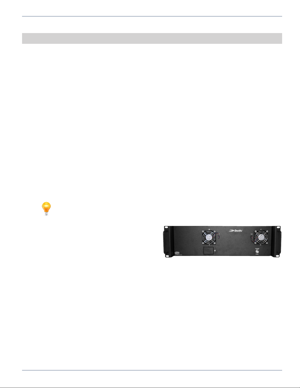
2.2.1 DigiVu® 3RU
This is the 3RU model with up to 10 channels of SD MPEG2 encoding or 5 channels of HD/SD MPEG-2/H.264. The
output is a single QAM. GbE IP output is available but
number of encoded channels is reduced for IP output, as
one card slot is used for the IP output card. This is a popular
model in applications where up to 10SD/5HD channels of
cost effective video are required in commercial sites such as
headends, MDUs, stadiums, hospitals and other health care
facilities where in-house educational channels are implemented.
Distinguishing Features:
• 3RU Chassis.
• 6 card slots for encoders or I/O cards. (Not all slots can be used for all card types.)
• Up to 10 integrated SD MPEG-2 encoded programs using dual encoder cards.
• Up to 5 integrated SD/HD MPEG-2/H.264 encoded programs.
Figure 2-1: 3RU DigiVu
®
DigiVu® Series Multichannel MPEG-2/H.264 Encoder/Multiplexer with QAM &/or IP Output - Installation & Operation Manual 2-1
Page 10

CHAPTER 2: SYSTEM DESCRIPTION
2.2.2 DigiVu® CD 3RU
This is very much the same as DigiVu with the addition of an
integrated channel dropping lter. This is a 3RU model with
up to 10 channels of SD MPEG-2 encoding or 5 channels of
HD/SD MPEG-2/H.264 where an existing cable TV channel
lineup requires that a channel be removed before inserting
the new QAM channel. The output is a single QAM. GbE
IP output is available but the number of encoded channels
is reduced for IP output, as one card slot is used for the IP
output card. This is a popular model in applications where up to 10SD/5HD channels of cost effective video are required in
commercial sites such as headends, MDUs, stadiums, hospitals and other health care facilities where in-house educational
channels are implemented.
Distinguishing Features:
• 3RU Chassis.
• Integrated (optional) Channel Dropping Filter.
• 6 card slots for encoders or I/O cards. (Not all slots can be used for all card types)
• Up to 10 integrated SD MPEG-2 encoded programs using dual encoder cards.
• Up to 5 integrated SD/HD MPEG-2/H.264 encoded programs.
2.2.3 DigiVu® Mini 1RU
This is the Mini 1RU model with up to 4 channels of HD/SD
MPEG-2/H.264. The output is single QAM. GbE IP output is
available but the number of encoded channels is reduced for
IP output, as one card slot is used for the IP output IP card.
This is a popular model in applications where up to 4SD/2HD
channels of cost effective video are required in commercial sites such as headends, MDUs, stadiums, hospitals and other
health care facilities where in-house educational channels are implemented.
Distinguishing Features:
• 1RU Chassis.
• 2 card slots for encoders or I/O cards.
• Up to 4 integrated SD MPEG-2 encoded programs using dual encoder cards.
• Up to 2 integrated SD/HD MPEG-2/H.264 programs encoded.
Figure 2-2: 3RU DigiVu® CD
Figure 2-3: 1RU DigiVu® Mini
2.3 The DigiVu® Encoder
DigiVu series products are headend or network-edge local content encoding devices for digital video networks. They encode
local baseband analog content into a digital format at the headend or within a property provisioned with digital only TVs, STBs
or DTAs where analog spectrum is not available or where digital content is needed in addition to analog content.
Target applications include:
• Cost-effective encoding, multiplexing & transmission (QAM and/or GigE).
• Headend application of digital simulcast or digital delivery of PEG.
• Hub site specic programming.
• Security or surveillance camera feeds (MDUs, retirement homes).
• Text/character generator or local information channel (hotels, conference centers, gated communities).
• Distribution of ‘in-house’ or private channels throughout a property (e.g., sports stadiums, network studios).
In addition to headend/hub applications, all deployments of digital signals in a modern cable TV system are presented with
challenges which did not exist in the former analog deployments. Specic challenges are faced when MDUs and institutions
within the cable plant require locally inserted content which must be received by the installed base of cable TV set top boxes
(STB). The DigiVu can be used in these properties to encode local analog video cameras, message boards, instructional
and advertising channels into HD/SD MPEG-2/H.264 streams. The resulting stream content may be inserted into a blank EIA
channel or may perform digital drop and insert into pre-existing clear QAM carriers or also perform Add/Drop Multiplexing
within a QAM channel. The exible architecture of the product makes it an ideal candidate for any number of programs that a
headend, hub, MDU or similar property is likely to require.
2-2 DigiVu® Series Multichannel MPEG-2/H.264 Encoder/Multiplexer with QAM &/or IP Output - Installation & Operation Manual
Page 11

2.4 Key Features
2.4.1 Flexible Digital Program Insertion
Designed for deployment in both RF and IP environments, the DigiVu system is capable of inserting digital programs into an
EIA RF channel where there is no pre-existing carrier or it may be used with an integrated channel deletion lter (DigiVu CD
Model) and any EIA channel may be effectively removed making way for a new QAM created by the DigiVu. The integrated
QAM modulator may be set to any frequency between 54 and 870 MHz (extended range 15 - 975 MHz with some restrictions)
in 1 kHz steps and fully supports STD, IRC and HRC channel plans. For IP distribution/insertion installations, Ethernet transport
streams may be created as either unicast or multicast, MPTS/SPTS with any address within the valid IPv4 address and port
range.
2.4.2 Support for SD/HD MPEG-2/H.264 Encoding
The DigiVu and DigiVu Mini platforms may be ordered with or eld upgraded with card slot plug-in SD or HD video encoders.
Each single channel HD plug-in card may be congured for SD or HD and can encode MPEG-2 or H.264 proles. If SD
programs only will need to be encoded, there are affordable single and dual channel SD encoder cards available. Both SD
and HD programs may be mixed on any output multiplex (IP or QAM) for best bandwidth efciency. Up to 2 HD programs may
be multiplexed to a QAM in the DigiVu Mini platform and up to 5 HD programs on the DigiVu platform. For platforms with IP
outputs, DigiVu Mini may output 1 HD program while the DigiVu may output up to 4 HD programs.
2.4.3 Gigabit Ethernet Output
The DigiVu systems may be provisioned with an optional gigabit Ethernet output card. The Ethernet card has 2 electrical
Ethernet ports (RJ45) as well as 2 SFP ports into which may be installed multimode ber optic SFPs for reliable trunk
connection to distribution switches. A variety of SFP interface types such as single mode and multimode ber are supported
and may be installed as required by system architecture. The Ethernet output may be provisioned to be the sole output of the
unit or simultaneous RF and Ethernet are supported. IP output streams may be provisioned with VLAN tagging and Pro-MPEG
FEC. If congured with IP output only(RF Disabled), then the IP programs may be all SPTS streams.
CHAPTER 2: SYSTEM DESCRIPTION
2.4.4 Integrated Add/Drop Multiplexing
Both DigiVu platforms have integral transport stream multiplexers which creates a new QAM or IP multiplex or alternately
may be used in an add/drop application along with an optional plug-in demodulator card to insert programs into an existing
QAM, clear or encrypted, replacing only the programs that are desired. If the program that is dropped was encrypted, the
replacement program stream will be in the clear. The add/drop application utilizes the QAM demodulator to analyze the MPEG
stream and selectively insert or “drop and insert” local programs in a exible manner.
2.4.5 Remote Monitoring Via SNMP
The product fully supports Simple Network Management Protocol (SNMP) which allows the monitoring of the built in alarm
points by a remote SNMP management console. The available DigiVu MIB may be compiled into the remote Management
Console to provide notication of the triggering of alarms either across a private network or the internet if available. Upon
triggering of a predened alarm, a trap is automatically sent by the DigiVu equipment to a listening SNMP management
console.
2.4.6 Flexible Transport Stream Re-Multiplexing
Flexibility is provided in conguring the re-multiplexed transport stream in an add/drop application. The inserted program may
be assigned any valid PID or MPEG program number and the encoder may be set to any of a wide range of valid CBR video
and audio encoding rates. A built in MPEG-2 stream analyzer (demodulator card required for this feature) for incoming MPEG
programs assists in making the correct selections for replacing programs easy and intuitive. MPEG tables PAT and PMT along
with all PID values are automatically generated to ensure that downstream STB can reliably tune the inserted multiplex and
minimum craft experience is required to implement a system. Dynamic PID monitoring avoids outages due to program table
updates.
2.4.7 Scalable Architecture is Field Upgradable
Encoder cards which accommodate one or two channels of SD MPEG-2 or one channel of HD/SD MPEG-2/H.264 encoding
may be installed as required so the system may be grown as needs grow. Hot swappable cards make upgrading the DigiVu
encoder capability faster while keeping outages to a minimum. The RF Demodulator card may be installed in any available
slot as future requirements dictate even if the initial installation did not originally include it. IP output capabilities may also be
added when required by installing a Gigabit Ethernet card in slots 2 (DigiVu Mini) or 5 (DigiVu and DigiVu CD).
2.4.8 Mass Deployment and Backup with Conguration Export
The DigiVu platforms allow the operator to export the programmed conguration as a le. The exported le may be used for
backup and archive purposes or to allow fast and easy deployment of multiple DigiVu units with similar conguration thus
DigiVu® Series Multichannel MPEG-2/H.264 Encoder/Multiplexer with QAM &/or IP Output - Installation & Operation Manual 2-3
Page 12
CHAPTER 2: SYSTEM DESCRIPTION
saving the time to manually program each unit before deployment.
NOTE: Care has to be taken not to overwrite the existing DigiVu IP address when loading
exported settings to remote units. This is avoided with factory default settings but may happen with
user congured settings.
2.4.9 IPv4 Network Address Support
All DigiVu platforms support IPv4 IP addressing and maybe congured with any valid IPv4 address to allow access from
private networks or from across the internet. For security against internet intrusion, the DigiVu unit forces assignment of a
username and password which may be changed at any time.
2.4.10 Optional Channel Deletion Filter (DigiVu® CD)
In applications where all cable plant channels have pre-existing QAM carriers, The DigiVu CD may be congured with an
optional channel deletion lter which allows the removal of any EIA channel and all of it’s RF content with minimal adjacent
channel affect, allowing a new QAM channel to be inserted.
2.4.11 Powerful GUI
Management and conguration of the DigiVu system is through a built-in web server which presents the conguration pages
in an intuitive tabbed format interface. Access to the GUI may be congured to allow remotely connecting across any private
network or over the Internet if a connection is made available, usually with a DOCSIS Cable Modem. For internet security, a
username and password provides controlled access against unauthorized persons.
2.4.12 Rack Mounting Enclosure
The DigiVu platform is constructed for deployment in a 19” rack mount installation environment. Integral cooling fans allow
the equipment to be installed and operate in a wide range of uncontrolled environmental conditions where room cooling is not
available.
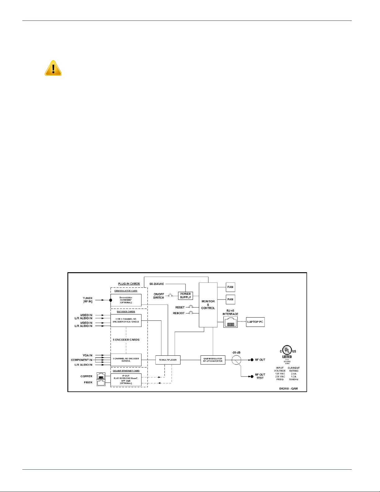
2.5 Simplied Block Diagrams
2.5.1 QAM Output
Figure 2-4: Simplied Block Diagram - QAM Output
2-4 DigiVu® Series Multichannel MPEG-2/H.264 Encoder/Multiplexer with QAM &/or IP Output - Installation & Operation Manual
Page 13
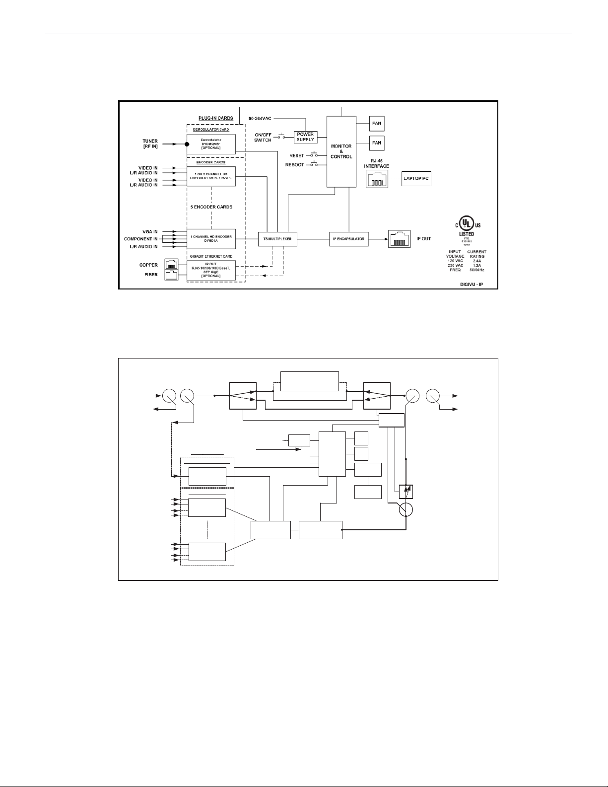
2.5.2 IP Output
CHAPTER 2: SYSTEM DESCRIPTION
Figure 2-5: Simplied Block Diagram - IP Output
2.5.3 DigiVu® CD (With RF Bypass)
-10 dB
-20 dB
RF IN
RF IN
TEST
TO
DEMODULATOR
PLUG
-IN CARDS
(PATCH CABLE)
DEMODULATOR CARD
QAM
DEMODULATOR
VIDEO IN
L/R AUDIO IN
VIDEO IN
L/R AUDIO IN
VIDEO IN
L/R AUDIO IN
VIDEO IN
L/R AUDIO IN
ENCODER CARDS
1 OR 2-CHANNEL
ENCODER
1 OR 2-CHANNEL
ENCODER
Figure 2-6: Simplied Block Diagram with RF Bypass - DigiVu® CD
90-264 VAC
QAM CHANNEL DELETION
FILTER - DGVUCD*
(OPTIONAL)
POWER
SUPPLY
REBOOT
RESET
QAM MODULATOR
RF-UPCONVERTER
MONITOR
CONTROL
DETECTOR
FAN
&
FAN
RJ-45
INTERFACE
LAPTOP
PC
RF SWITCH RF SWITCH
ON/OFF SWITCH
TS MULTIPLEXER
-20 dB
-20 dB
RF
RF SWITCH
-20 dB
RF OUT
RF OUT
TEST
DigiVu CD
DigiVu® Series Multichannel MPEG-2/H.264 Encoder/Multiplexer with QAM &/or IP Output - Installation & Operation Manual 2-5
Page 14
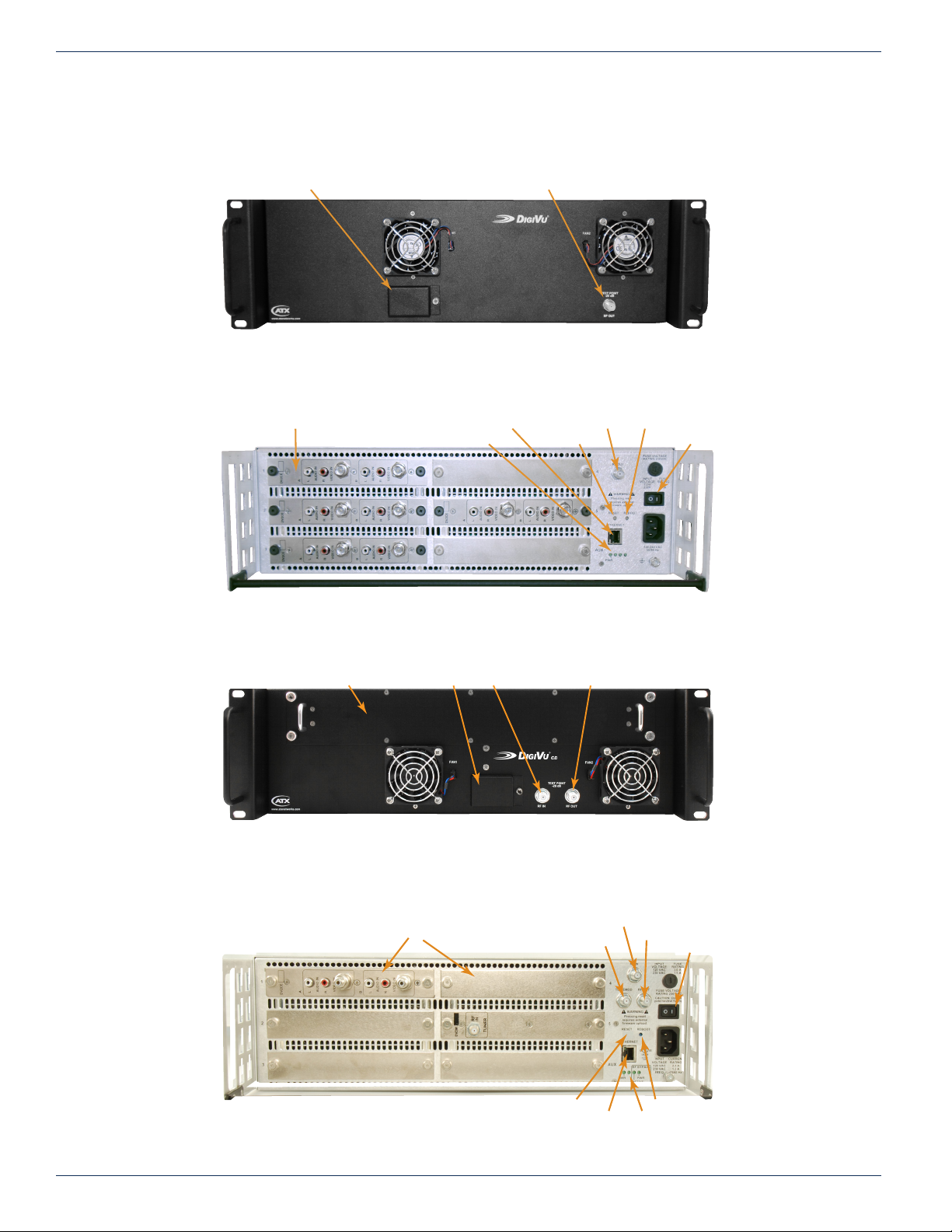
CHAPTER 2: SYSTEM DESCRIPTION
Realtime Clock Battery
RF Output Test Point
Management Ethernet Port
Power Indicator
RF Input Port
2.6 Front and Rear Panels
2.6.1 DigiVu® Front
2.6.2 DigiVu® Rear
Encoder and I/O Card Slots
Figure 2-7: DigiVu® Front
Management Ethernet Port RF Output Port Reboot Button
Reset ButtonPower Indicator
Power Switch
2.6.3 DigiVu® CD Front
2.6.4 DigiVu® CD Rear
Channel Dropping Filter
Figure 2-8: DigiVu® Rear
Realtime Clock Battery RF Output Test PointRF Input Test Point
Figure 2-9: DigiVu
Encoder and I/O Card Slots
®
CD Front
Out to Demod
RF Output Port
Power Switch
Reboot ButtonReset Button
Figure 2-10: DigiVu® CD Rear
2-6 DigiVu® Series Multichannel MPEG-2/H.264 Encoder/Multiplexer with QAM &/or IP Output - Installation & Operation Manual
Page 15
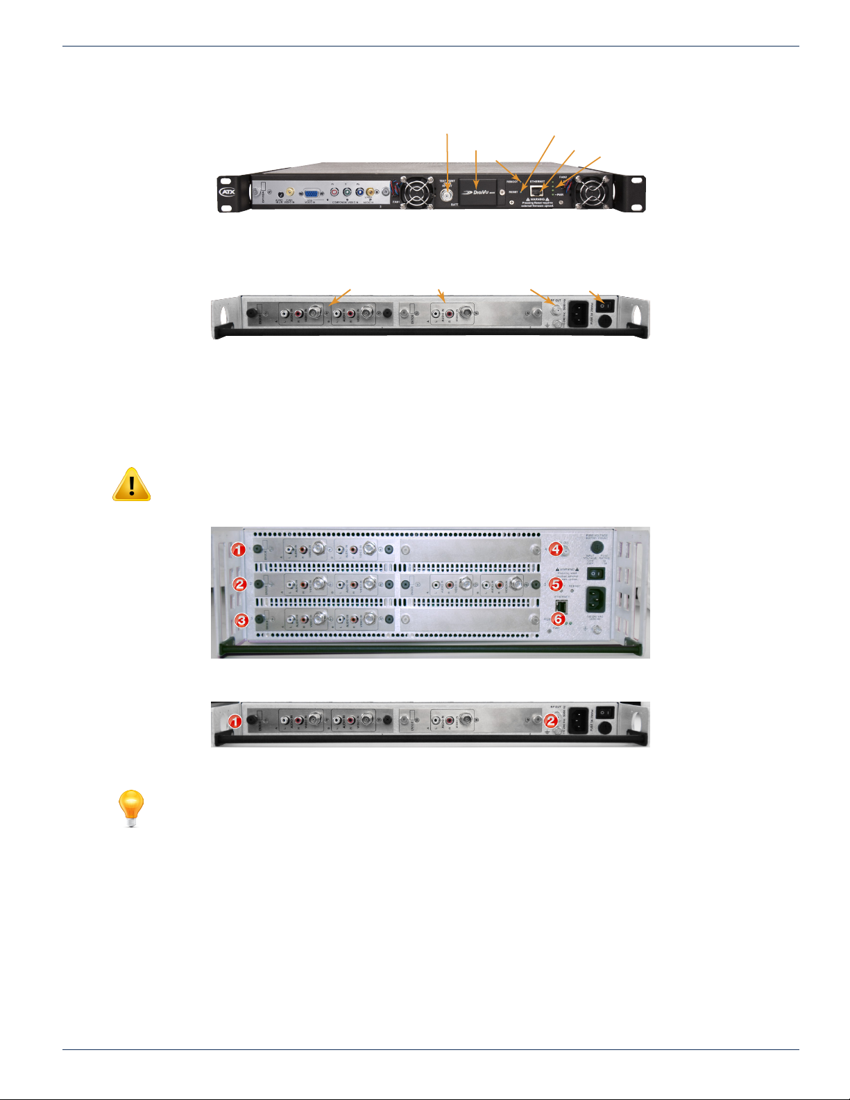
2.6.5 DigiVu® Mini Front
RF Output Port Power SwitchEncoder and I/O Card Slots
2.6.6 DigiVu® Mini Rear
2.7 Card Slot Numbering
All plug-in cards are installed in a slot on the rear panel which are numbered 1 through 5 plus AUX (6th slot) on the DigiVu and
DigiVu CD, see Figure 2-13, and numbered 1 & 2 on the DigiVu Mini, see Figure 2-14. See the card support table below for
correct card insertion. Be careful to align the circuit board of the card with the internal card guides when re-inserting the cards.
RF Output Test Point
Realtime Clock Battery
Reboot Button
Figure 2-11: DigiVu® Mini Front
Figure 2-12: DigiVu® Mini Rear
CHAPTER 2: SYSTEM DESCRIPTION
Reset Button
Management Ethernet Port
Power Indicator
NOTE: The 6th card slot in the DigiVu 3RU platforms is for power only to cards which do not
require management, as this slot does not show up in the GUI. Currently, this slot is exclusively
used for the 2-Way A/V Splitter card but the A/V Splitter card may be installed in any slot if required.
Figure 2-13: DigiVu® 3RU Card Slot Numbers
Figure 2-14: DigiVu® 1RU Card Slot Numbers
FYI: For information on the way the GUI displays installed cards see “6.5.1 Port Numbering
Convention” on page 6-3.
DigiVu® Series Multichannel MPEG-2/H.264 Encoder/Multiplexer with QAM &/or IP Output - Installation & Operation Manual 2-7
Page 16
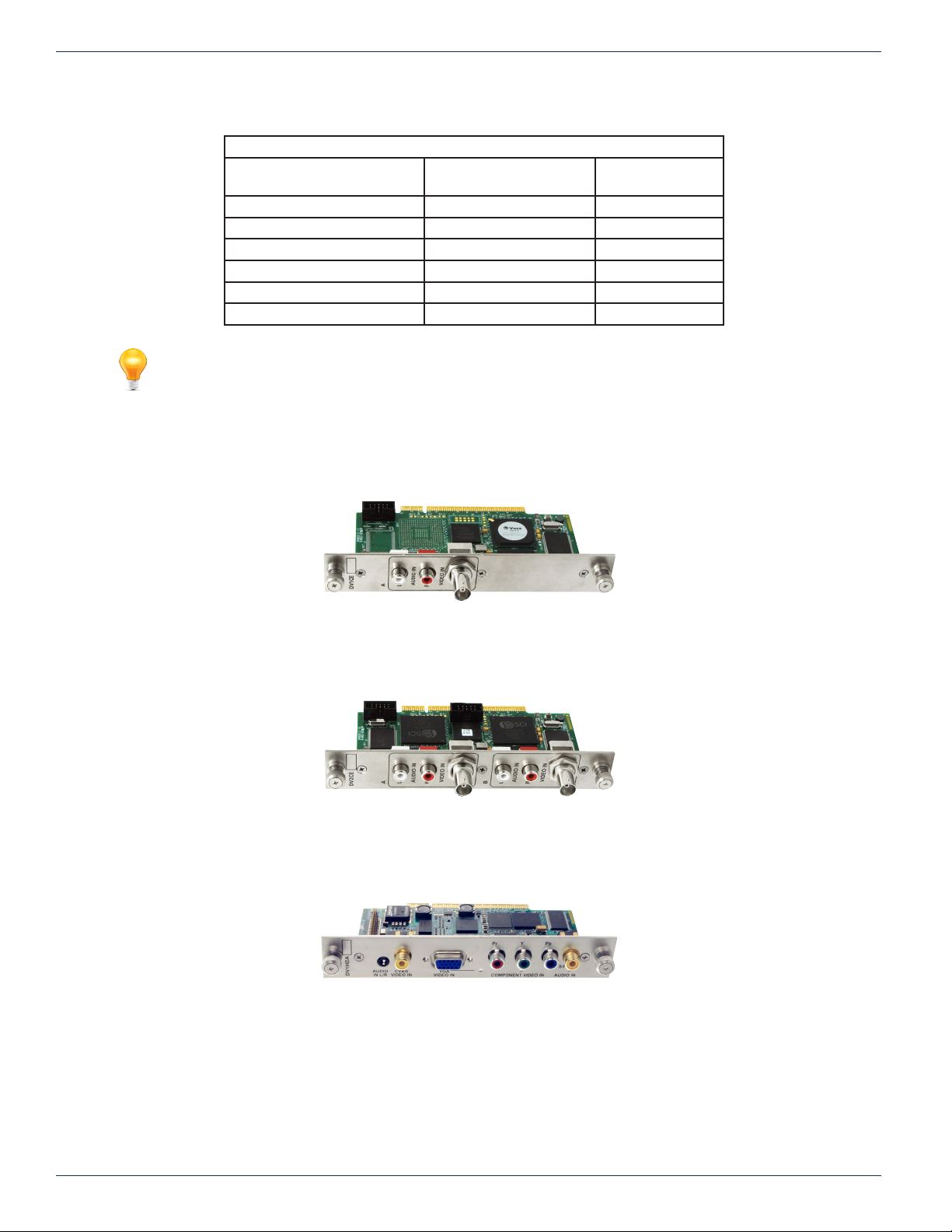
CHAPTER 2: SYSTEM DESCRIPTION
2.7.1 Card Slot Support
DigiVu®, DigiVu® CD & DigiVu® Mini Card Support
Card Type
Single Channel HD Encoder 1, 2, 3, 4, 5 1, 2
Single Channel SD Encoder 1, 2, 3, 4, 5 1, 2
Dual Channel SD Encoder 1, 2, 3, 4, 5 1, 2
Demodulator 1, 2, 3, 4, 5 1, 2
Gigabit Ethernet 5 2
2-Way Audio/Video Splitter 1, 2, 3, 4, 5, AUX 1, 2
NOTE: All cards are hot pluggable so there is no need to interrupt power to change cards.
2.8 Available Encoder Cards
2.8.1 DV1CE & DV1CEM Single Channel SD Card
DigiVu & DigiVu CD
Supports in Slots
DigiVu Mini
Supports in Slots
Figure 2-15: Single Channel SD Encoder
2.8.2 DV2CE & DV2CEM Dual Channel SD Card
Figure 2-16: Dual Channel SD Encoder
2.8.3 DV1HDA Single Channel HD/SD Card
Figure 2-17: Single Channel HD/SD Encoder
2-8 DigiVu® Series Multichannel MPEG-2/H.264 Encoder/Multiplexer with QAM &/or IP Output - Installation & Operation Manual
Page 17
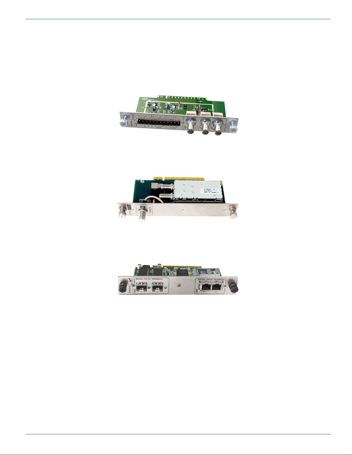
2.9 Available Input/Output Cards
2.9.1 DV1DA Distribution Amplier
Figure 2-18: 2-Output A/V Distribution Amplier
2.9.2 DVDMQMB & DVDMQMAC QAM Modulator
CHAPTER 2: SYSTEM DESCRIPTION
2.9.3 DVGIGE Gigabit Ethernet Card
Figure 2-19: QAM Demodulator
Figure 2-20: Gigabit Ethernet Output Card
DigiVu® Series Multichannel MPEG-2/H.264 Encoder/Multiplexer with QAM &/or IP Output - Installation & Operation Manual 2-9
Page 18

This page intentionally left blank
CHAPTER 2: SYSTEM DESCRIPTION
DigiVu® Series Multichannel MPEG-2/H.264 Encoder/Multiplexer with QAM &/or IP Output - Installation & Operation Manual 2-10
Page 19

FIELD APPLICATIONS
3. Field Applications
In this chapter we illustrate some of the common eld applications for the DigiVu systems. This listing is not exhaustive and
does not show every combination of channel or program encoding/insertion. Reference to DigiVu infers all DigiVu platforms
unless a specic model is stated.
FYI: In this guide, reference to DigiVu infers DigiVu 3RU, DigiVu CD 3RU and DigiVu Mini 1RU
unless the model is specically stated. Reference to DVIS is synonymous with DigiVu as these
products run on the same rmware.
3.1 Chapter Contents
• “Summary of Insertion Applications”
• “Analog Channel Insertion vs Digital Channel Insertion”
• “QAM Insertion Without Decoding”
• “Insertion Into Under-utilized QAM (Add/Drop)”
• “IP Video Content Insertion”
• “Local Content Back Haul Over IP”
CHAPTER 3: FIELD APPLICATIONS
3.2 Summary of Insertion Applications
3.2.1 Insertion of a Carrier Into a Blank or Empty Channel Spectrum
It is possible to insert the DigiVu QAM carrier into spectrum space left intentionally blank without the use of a channel deletion
lter. Generally the two scenarios for insertion are in between existing adjacent system channels and at the upper edge of the
cable system passband.
See “QAM Insertion Without Decoding” on page 3-3
3.2.2 Insertion of a Carrier with use of a Deletion Filter to Remove an Existing Carrier
Using the optional channel deletion lter, the target system channel may be effectively removed to make space for the inserted
channel. In this case, adjacent system channels are minimally affected through the DigiVu “Brick Wall” channel dropping lter
technology.
See “Insertion into Locally Deleted QAM” on page 3-4
3.2.3 Digital Program Insertion into an Existing QAM with Existing Programs
This application is intended for ‘in the clear’ or encrypted QAM channels that have programming that is able to be sacriced
or for QAM channels that are designed for this program insertion feature. Encrypted programs will be replaced with an ‘in the
clear’ program.
See “Insertion into Under-utilized QAM (Add/Drop)” on page 3-4
3.2.4 IP Video Content Insertion
This application uses the DigiVu encoding capability with IP output to locally insert programming into an IPTV property or
remote hub for distribution or Headend encoding application.
See “IP Video Content Insertion” on page 3-5
3.2.5 Video Back Haul Schemes
These applications uses the DigiVu encoding capability with IP output, QAM output to haul a special remote origination
program to a hub for distribution.
“Local Content Back Haul Over IP” on page 3-6
DigiVu® Series Multichannel MPEG-2/H.264 Encoder/Multiplexer with QAM &/or IP Output - Installation & Operation Manual 3-1
Page 20
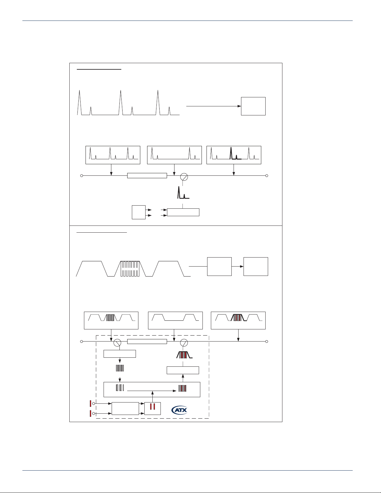
CHAPTER 3: FIELD APPLICATIONS
3.3 Analog Channel Insertion vs Digital Channel Insertion
Old Way – Analog System
One Channel contains one Program
One channel is deleted
A new program is modulated and reinserted
All channels can be tuned by an Analog TV Tuner
1 PROGRAM 1 PROGRAM 1 PROGRAM
ANALOG CHANNEL ANALOG CHANNEL ANALOG CHANNEL
All original channels minus
All original channels before
the Channel Deletion Filter
PROGRAM
ANALOG
CHANNEL
CABLE TV IN
1
PROGRAM
ANALOG
CHANNEL
1
1
PROGRAM
ANALOG
CHANNEL
one channel after the Channel
PROGRAM
ANALOG
CHANNEL
CHANNEL DELETION FILTER
NEW
CHANNEL
SOURCE
MATERIAL
AUDIO
VIDEO
Deletion Filter
1
DELETED
CHANNEL
New Way – All Digital System
One Channel can typically contain up to 10 programs
One channel is deleted
Any number of programs within that channel can be “dropped”
One to Four new programs can be “added”, modulated and inserted
The new channel can only be tuned with a Digital Set-Top Box
PROGRAMS
NEW
PROGRAM
ANALOG
CHANNEL
MODULATOR
ANALOG
1
PROGRAM
ANALOG
CHANNEL
DIRECTIONAL
COUPLER
DIGITAL
All original channels plus new
channels after the directional
coupler
1
PROGRAM
ANALOG
CHANNEL
SET-TOP
BOX
PROGRAM
ANALOG
CHANNEL
NEW
CHANNEL
TV
PROGRAM
ANALOG
1
CABLE TV OUT
TV
DIGITAL CHANNEL DIGITAL CHANNEL DIGITAL CHANNEL
All original channels minus
All original channels before
the Channel Deletion Filter
PROGRAMS
DIGITAL
DIGITAL CHANNEL
CHANNEL
CABLE TV IN CABLE TV OUT
NEW
PROGRAM 1
NEW
PROGRAM 2
CHANNEL
DEMODULATOR
ORIGINAL
PROGRAMS
DROPPED
PROGRAMS
ENCODER
DIGITAL
one channel after the Channel
DIGITAL CHANNEL DIGITAL CHANNEL
CHANNEL DELETION FILTER
MULTIPLEXER
NEW
PROGRAMS
Deletion Filter
DELETED CHANNEL
NEW AND OLD PROGRAMS
MODULATOR
NEW AND OLD
PROGRAMS
DIRECTIONAL
COUPLER
DVISm
All original channels plus new
channel and added programs
after the directional coupler
NEW AND OLD
DIGITAL
CHANNEL
DIGITAL CHANNEL
PROGRAMS
DIGITAL
CHANNEL
Figure 3-1: Analog Channel Insertion vs Digital Channel Insertion
3-2 DigiVu® Series Multichannel MPEG-2/H.264 Encoder/Multiplexer with QAM &/or IP Output - Installation & Operation Manual
Page 21
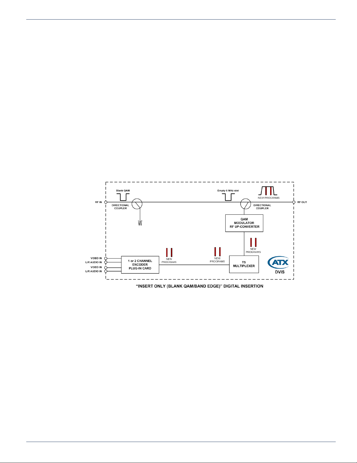
3.4 QAM Insertion Without Decoding
3.4.1 Insertion Into Empty Channel
DigiVu series products can be used to insert local programming into the cable system where there is empty spectrum (no QAM
or analog channel). This can be spectrum in the middle of other channels or above the HFC plant end frequency (at the “band
edge”). In these scenarios, a channel is allocated on the system where no carrier is sent from the headend and every property
in the system where the DigiVu is installed may insert a QAM without the use of a channel deletion lter. When RF spectrum
is available for this application and/or there are a large number of insertion systems installed, the cost of a channel deletion
lter may be saved at every property.
3.4.2 Insertion Into Channel at Band Edge
There are two main scenarios for this deployment:
• Regular 870 MHz plant has some empty channels remaining unused just below 870 MHz. The new QAM channel is
inserted on one of these empty channels.
• Plant is built to 750 so at least 100 MHz of plant is available with empty channels. The new QAM is inserted in this
upper band above the 750 plant.
In each case, some extra loss may be incurred through passives that are near or past their usable bandwidth but in such
a case, only a very few passives are affecting the new QAM channel and the DigiVu output may be increased slightly to
compensate if required.
CHAPTER 3: FIELD APPLICATIONS
Figure 3-2: Insertion Into Channel at Band Edge
DigiVu® Series Multichannel MPEG-2/H.264 Encoder/Multiplexer with QAM &/or IP Output - Installation & Operation Manual 3-3
Page 22
CHAPTER 3: FIELD APPLICATIONS
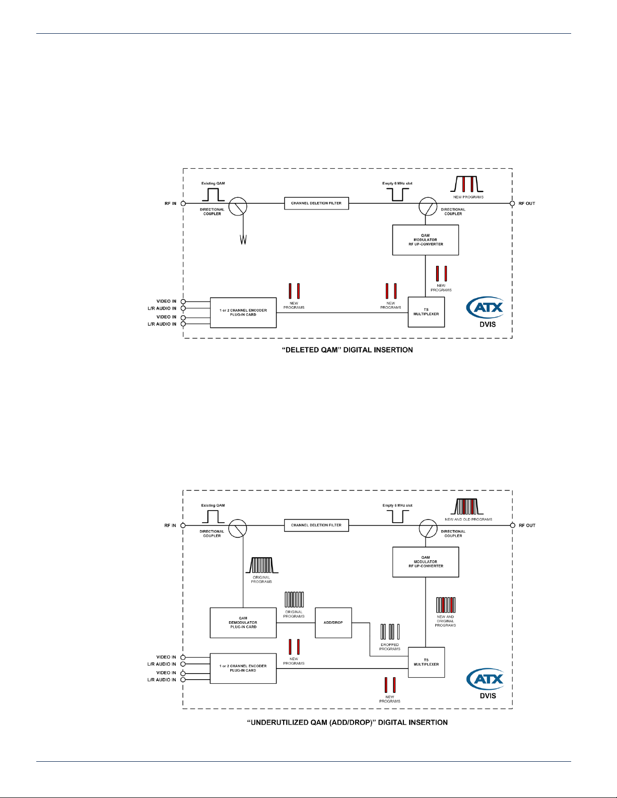
3.4.3 Insertion Into Locally Deleted QAM
The DigiVu CD product can be used to insert local programming into an EIA channel where the cable system carries a
channel but providing customers with the programming on that channel is discretionary. In this scenario, a system EIA channel
is deleted using an optional channel deletion lter with very good adjacent channel performance and deep rejection of the
intended deletion channel. This lter is available from ATX Networks and is an integral part of the design of the DigiVu CD.
In this case, the DigiVu CD will create a totally new QAM channel and insert it into the blank spectrum following the output of
the lter.
Figure 3-3: DigiVu® CD - Insertion into Locally Deleted QAM
3.5 Insertion Into Under-utilized QAM (Add/Drop)
3.5.1 Locally Add/Drop Programs in a QAM
The DigiVu CD can be used to insert local programming into the actual data stream of a QAM by dropping specic programs
from an existing QAM channel and replacing them with local content. This application requires optional DEMOD Card and
Channel Deletion Filter. In this application, the original system EIA channel is ltered out and a new QAM channel inserted
Figure 3-4: Locally Add/Drop Programs in a QAM
3-4 DigiVu® Series Multichannel MPEG-2/H.264 Encoder/Multiplexer with QAM &/or IP Output - Installation & Operation Manual
Page 23
in it’s place, however, before deletion the incoming QAM channel is demodulated and de-multiplexed. This allows insertion
of local content in a more granular manner, right at the program level. Any incoming programs may be selected to be deleted
even an encrypted program, and in their place, SD or HD programs may be inserted. Replaced programs will be ‘in the clear’.
This has the benet of retaining programs in the QAM that must remain and using the deleted program space to provide
the local content to the property. Only content payload is manipulated (dropped/replaced/added). All other data/tables from
incoming QAM is passed through without affecting it.
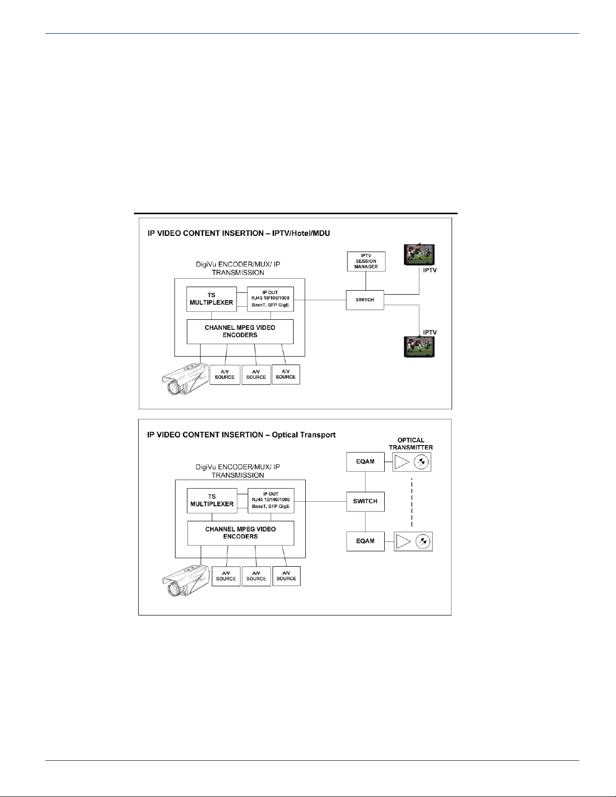
3.6 IP Video Content Insertion
The DigiVu platform with GbE output card may be used to insert IP video content directly to a network switch for transmission
on the plant in a hotel or other hospitality environment or transported via Edge QAM and optical for remote delivery.
CHAPTER 3: FIELD APPLICATIONS
Figure 3-5: IP Video Content Insertion
DigiVu® Series Multichannel MPEG-2/H.264 Encoder/Multiplexer with QAM &/or IP Output - Installation & Operation Manual 3-5
Page 24
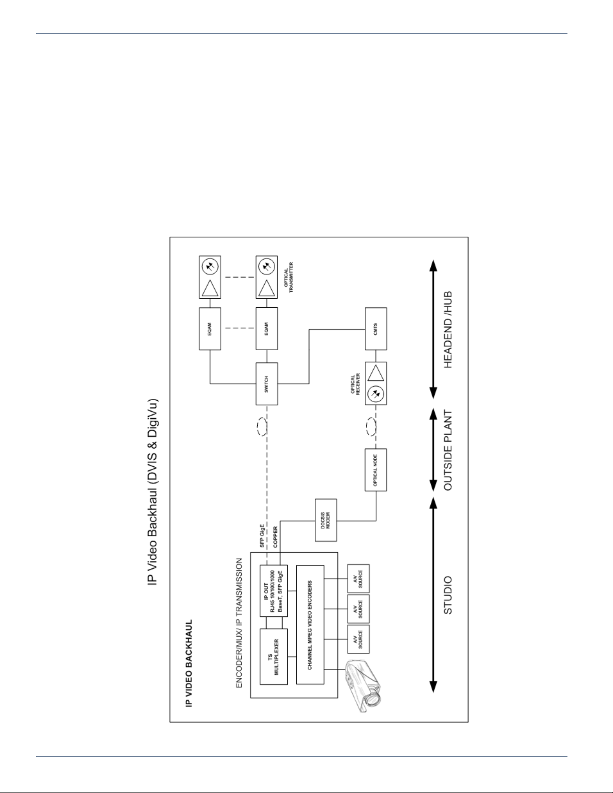
CHAPTER 3: FIELD APPLICATIONS
3.7 Local Content Back Haul Over IP
DigiVu systems may be used for IP back haul where there is a source of video at a point in the plant such as a remote studio
or special program origination location and the video is needed at a hub for reinsertion into the plant. There are two main
applications as illustrated in Figure 3-6.
1. Fiber Back Haul
This provides guaranteed signal quality, link speed and bandwidth. In this case, a single mode SFP may be used to
transport the IP stream on the ber.
2. DOCSIS modem Back Haul
Not always possible to guarantee link speed and bandwidth which could vary, therefore encoded signal quality must
be lower due to lower upstream bandwidth. In this case a DOCSIS modem with high rate upload speed is used to
transmit the video over IP to the hub, where it is re-inserted.
Figure 3-6: Local Content Back Haul Over IP
3-6 DigiVu® Series Multichannel MPEG-2/H.264 Encoder/Multiplexer with QAM &/or IP Output - Installation & Operation Manual
Page 25
INSTALLATION
4. Installation
This chapter outlines the most important aspects of the installation and summarizes the site considerations that the installer
must take into account when choosing a location for the unit. Reference to DigiVu infers both DigiVu and DigiVu Mini unless
specically stated.
FYI: In this guide, reference to DigiVu infers DigiVu 3RU, DigiVu CD 3RU and DigiVu Mini 1RU
unless the model is specically stated. Reference to DVIS is synonymous with DigiVu as these
products run on the same rmware.
4.1 Chapter Contents
• “Recommended Installation Environment”
• “Equipment Safety Grounding”
• “RF Cable Sheath Grounding”
• “Mounting”
• “Environment Considerations”
• “RF Cabling”
• “Ethernet Network”
• “Installing Modules”
CHAPTER 4: INSTALLATION
4.2 Recommended Installation Environment
Carefully unpack the equipment from the shipping box. If the box or equipment is damaged, notify the freight company to make
a damage claim. If you suspect that there is a problem with the equipment that may compromise safe operation, do not install
or operate it.
NOTE: This equipment is intended for installation in a RESTRICTED ACCESS LOCATION only.
Not for use in a computer room as dened in the Standard for Protection of Electronic Computer/
Data Processing Equipment, ANSI/NFPA 75. This equipment is intended for use in a xed position
and should be installed securely before operation is undertaken.
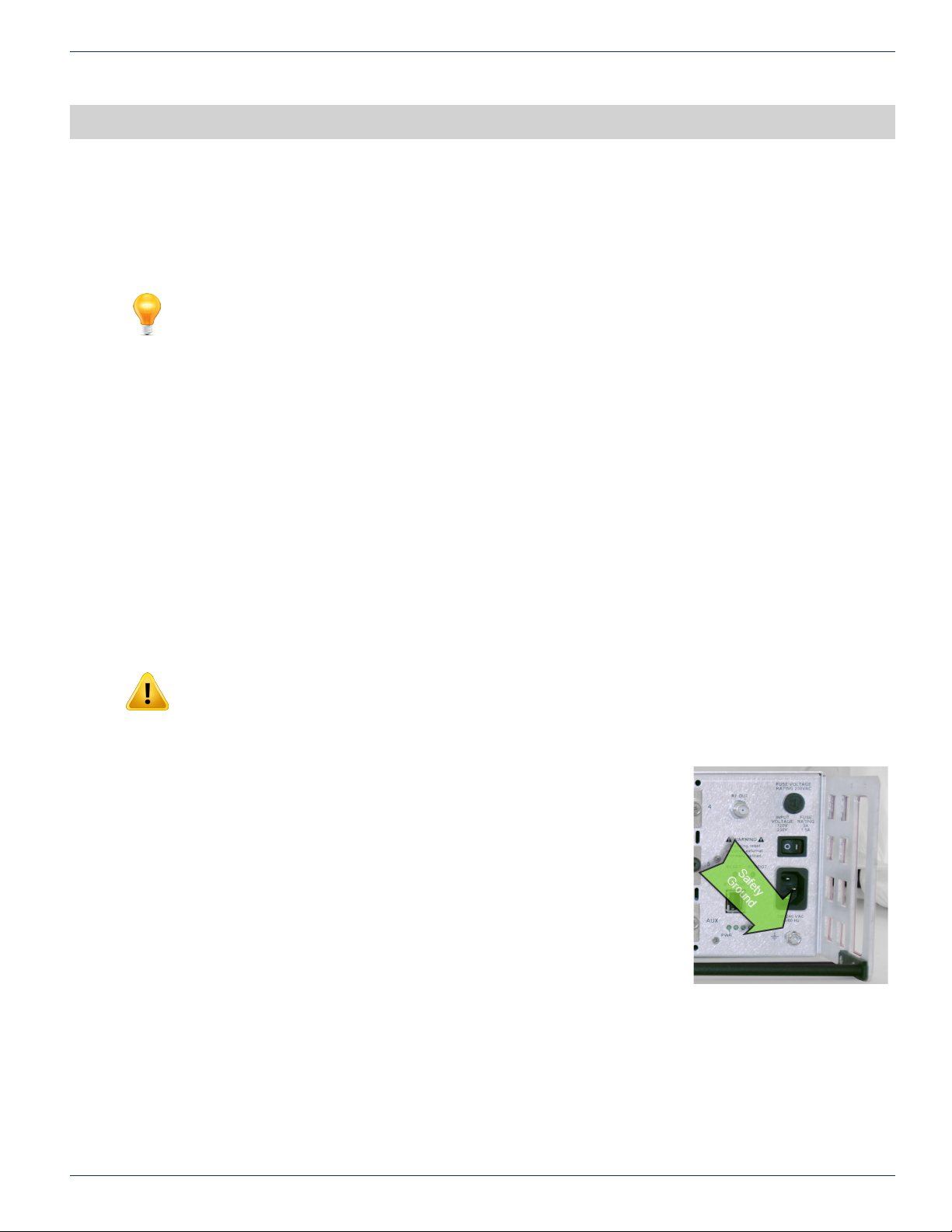
4.3 Equipment Safety Grounding
It is imperative that the chassis be connected to a permanent building ground in a manner
that will ensure that the exposed metal parts are constantly connected to ground even
when the power cord may be disconnected temporarily. A grounding lug is provided on the
front panel to conveniently effect such a connection. The following guidelines are provided
to clarify the requirements for the installation to meet UL, CUL and CB standards. The use
of the words “Ground” and “Earth” as well as “Grounding” and “Earthing” may be used
interchangeably and in this context, have the same meaning.
4.3.1 Connection to Earth
The supplementary equipment grounding conductor is to be installed between the back
panel ground connector and earth, that is, in addition to the equipment ground conductor
in the power supply cord.
4.3.2 Conductor Size
The supplementary equipment grounding conductor may not be smaller in size than the branch-circuit supply conductors
or a minimum #14 AWG. The supplementary equipment grounding conductor is to be connected at the back panel terminal
provided, and connected to earth in a manner that will retain the earth connection when the power supply cord is unplugged.
The connection to earth of the supplementary grounding conductor shall be in compliance with the appropriate rules for
terminating bonding jumpers in Part V of Article 250 of the National Electrical Code, ANSI/NFPA 70, and Section 10 of Part I
of the Canadian Electrical Code, Part I, CSA C22.1.
Figure 4-1: Safety Ground Lug
DigiVu® Series Multichannel MPEG-2/H.264 Encoder/Multiplexer with QAM &/or IP Output - Installation & Operation Manual 4-1
Page 26

CHAPTER 4: INSTALLATION
4.3.3 Conductor Termination
Termination of the supplementary equipment grounding conductor may be made to building steel, to a metal electrical raceway
system, or to any grounded item that is permanently and reliably connected to the electrical service equipment earth.
4.3.4 Conductor Type
Bare, covered or insulated grounding conductors are acceptable. A covered or insulated grounding conductor shall have a
continuous outer nish that is either green, or green with one or more yellow stripes.
4.4 RF Cable Sheath Grounding
4.4.1 Requirement to Ground the Coaxial Cable Sheath
In addition to the supplementary ground to the equipment, it is also required to ground the sheath of the RF coaxial cable at
it’s point of entrance to the building. If the chassis is installed at a location removed from the point of coaxial cable entrance,
it is the installer’s responsibility to ensure that the grounding of the sheath has already been performed in accordance with
electrical code directives.
4.4.2 Size of Grounding Conductor
The size of grounding conductor and the manner of attachment to the coaxial cable should be in accordance with the national
electrical safety regulations in effect in the country in which the installation is located.
4.4.3 Minimize Coaxial Cable Sheath Currents
Care should be taken when grounding the coaxial cable sheath to ensure that circulating currents are minimized to prevent
interference on the RF signal. This ground loop condition may be minimized by connecting the coaxial cable sheath grounding
conductor to the same building ground point as the chassis safety ground conductor attachment.
4.5 Mounting
4.5.1 Rack Mounting
The chassis is intended to be mounted in a standard 19” EIA equipment rack. A reasonable amount of space will be required
in front of and behind to allow installation and servicing. The equipment is designed with fan forced cooling which exhausts
to the top and side of the unit. Avoid blocking airow at the top and sides and mount in such a manner to provide a source of
ambient cool air at the front fan air intake grill. Provide at least one open rack space above the chassis. Consider also that the
site technician will need access to the front and back of the unit for accessing connections, maintenance and conguration
when determining the best mounting location.
4.5.2 Mounting Precautions
FYI: See “Equipment Safety Grounding” on page 4-1 for detailed information on grounding.
1. Elevated Operating Ambient:
If installed in a closed environment that may exceed room ambient temperature, consideration should be given to
installing the equipment in an environment compatible with the maximum ambient temperature specied (50°C).
2. Reduced Air Flow:
Installation should allow at least 2” spacing around the equipment to ensure that airow required for proper operation
is not compromised. At least one blank rack space above the unit should be allowed.
3. Mechanical Loading:
Mounting of the equipment should be according to the installation instructions so that a hazardous condition is not
created due to improper mechanical loading. Do not use the DigiVu to mechanically support other equipment.
4. Circuit Overloading:
Consideration should be given to the connection of the equipment to the supply circuit and the effect that overloading
of the circuit will have on over-current protection and supply wiring. Consider equipment nameplate ratings when
addressing this concern.
5. Reliable Earthing:
The chassis must be connected to a reliable ground or earth connection with an adequately sized copper conductor.
See “4.3 Equipment Safety Grounding” on page 4-1.
4-2 DigiVu® Series Multichannel MPEG-2/H.264 Encoder/Multiplexer with QAM &/or IP Output - Installation & Operation Manual
Page 27

4.6 Environment Considerations
4.6.1 Ambient Temperature
The chassis must be installed in a room where the ambient air temperature does not exceed +122°F (+50°C). This is a
maximum temperature that must not be exceeded but the preferred temperature range is one where people feel most
comfortable.
4.6.2 Non-condensing Environment
The environment must be non-condensing. This means that a relative humidity of less than 95% must be maintained. Lower
humidity is better and the preferred humidity range is one where people feel most comfortable.
4.6.3 Fan Control
The equipment is designed to operate to specication in an ambient room temperature of 0°C to +50°C (+32°F to +122°F).
Sufcient airow through the unit must be maintained regardless of the mounting location. It is imperative that other equipment
or materials of any type do not block free airow at the front and top/back of the chassis. There are no internal air lters so
there is no need to provide ongoing maintenance of lters.
4.7 Provisioning Electrical Power
4.7.1 Power Cord Protection
Measures must be taken during installation to route or arrange the power supply cord to prevent physical damage to the
cord and to avoid the possibility of future damage occurring. The power supply cord shall be installed and routed such that,
throughout it’s length, the cord and it’s points of connection are not strained in any way.
CHAPTER 4: INSTALLATION
4.7.2 Power Cord Attachment:
The power supply cord shall not be attached to the building surface, bundled with audio, video or RF coaxial cables, nor run
through walls, ceilings, oors and similar openings in the building structure.
4.7.3 Provision of Electrical Power Outlet:
An electrical power outlet of appropriate type and rating shall be provided near the location where the chassis is installed such
that the provided power supply cord may be routed in an appropriate manner, without the use of extension cords, between the
receptacle and the chassis. Alternately, the chassis shall be installed in close proximity to an existing electrical outlet such that
the requirements of this paragraph are achieved.
4.7.4 IEC Power Input Cord
The power input receptacle is a standard IEC connector similar to that commonly used on computers and monitors. The power
cord provided is dependant on the shipping address of the equipment. If shipped in North America a cord with a NEMA 5-15
grounded plug for 115 VAC is provided. If it is necessary to operate the equipment on 230 VAC, the installer must obtain an
IEC cord with a NEMA 6-15 grounded plug for use in North America. This may be obtained from ATX Networks or locally. If
shipped outside of North America, the equipment will be shipped with an IEC cord set appropriate for the locale.
4.7.5 Input Power Requirements
When installing equipment, it is the responsibility of the installer to determine that sufcient capacity is available in the electrical
circuit feeding the unit to avoid overloading the supply circuit. Each model will require power according to it’s specications to
be supplied from a properly grounded outlet. The installer should determine that the power outlet, its wiring and receptacle is
in compliance with the local electrical codes.
4.7.6 Input Power
The input power requirement is constant over the range of input voltages. At higher input voltages, the current consumption is
lower than it is at lower voltages where the input current is higher.
4.7.7 Input Voltage Range
The equipment is supplied with an autosensing switching type power supply which can operate on input voltages from 90 VAC
to 264 VAC. There is no need to congure the power supply to operate on any voltage within this range.
4.7.8 Fusing
The internal power supply is protected from over current conditions with a slow blow fuse. Replace with similar type and rating
to avoid over-current circuit damage. The following table describes the fuse if replacement ever becomes necessary.
DigiVu® Series Multichannel MPEG-2/H.264 Encoder/Multiplexer with QAM &/or IP Output - Installation & Operation Manual 4-3
Page 28
CHAPTER 4: INSTALLATION
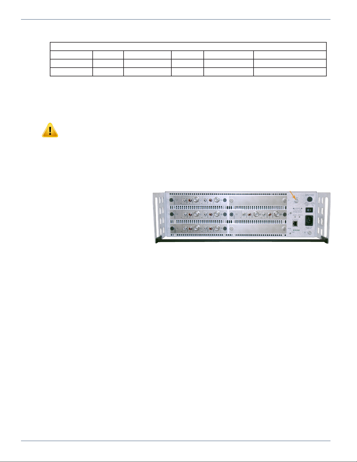
RF Out
Input Voltage Model Fuse application Fuse Type Ampere rating Fuse size
115 VAC All AC IN Slow Blow 3 5 x 20 mm glass tube
230 VAC All AC IN Slow Blow 1.5 5 x 20 mm glass tube
4.8 RF Cabling
RF cabling to the chassis should be either RG6/u or RG59/u style double or triple shield coaxial cable of a type UL approved
for Cable TV applications. There is no restriction on using RG6/u cable on the F Fittings. Connectors should be very lightly
wrench tightened according to Cable Service Provider’s company policy.
NOTE: Final connection of the RF output to the distribution network should only be completed
when the installer has completed conguration. An incompatible conguration, if it was installed or
congured elsewhere, may create a situation where output RF Levels are incompatible with the
premises. This may result in unintended service outages.
4.8.1 RF Output Connector
The accompanying graphic illustrates the rear panel. A diagram, “Simplied Block Diagrams” on page 2-4 may be referenced
for details of interconnections.
Fuse Replacement Criteria - All Models
4.8.2 RF Input Levels
If the DigiVu chassis has been tted with a
demodulator module, then the input signal
level presented to the RF input of the module
must be in the range of +5 to +14 dBmV per
digital carrier as measured with a digital eld
meter. If local conditions dictate that a higher
or lower signal level is available, the installer
must install appropriate external attenuation
or may install a coupler to ensure the input
specication is met. External RF attenuators
and couplers that may be necessary depend
on site conditions and are not supplied.
4.8.3 RF Output Level
The RF output connector is 75 Ω “F” Type female. The output level from the QAM modulator is 57.5 +/- 1.5 dBmV. The GUI
provides an internal adjustable attenuator of up to 26 dB in 1 dB steps to reduce this level to match application specic RF
levels. Try to adjust the modulator output QAM level to closely match adjacent channels on the nal system combining network.
4.9 Audio & Video Connections
4.9.1 Video Cable Recommendation
Coaxial
It is recommended to utilize double or triple shielded 75 Ω coaxial cables with BNC or RCA (depending on encoder card)
connectors or adapters for video signals. UL approved coaxial cables that are in general use in Cable TV systems will usually
be satisfactory. Observe re and smoke rating of cables and the installation environment to ensure compliance with all local
codes. Cables shall be routed and connectors and adapters attached such that terminal connections are not strained.
VGA
Usually a pre-manufactured VGA cable is used if this is the input signal type. Lengths up to about 50 meters may be available
but specify a plenum rated cable if the cables of this length which leave the equipment room will be installed. Cables shall be
routed and connectors and adapters attached such that terminal connections are not strained.
Figure 4-2: DigiVu® Rear Panel RF Output
4.9.2 Video Port Connectors
The MPEG-2 encoders are provided with a BNC female connector for SD video input . For convenience a BNC male to RCA
female adapter is provided on each video input port as this is a common requirement in many installations.
The MPEG-2/H.264 encoders are provided with 3 x RCA female connector (component) and DE-15 female connector (VGA).
4-4 DigiVu® Series Multichannel MPEG-2/H.264 Encoder/Multiplexer with QAM &/or IP Output - Installation & Operation Manual
Page 29
4.9.3 Video Input Levels
Video Input level is expected to be 1 volt P-P although a higher and lower signal voltage may be tolerated by adjusting the
video level control in the GUI. See “Brightness: [0-255]” on page 6-6 for a possible work around for low level video.
4.9.4 Audio Cable Recommendation
It is recommended to utilize double or triple shielded 75 Ω coaxial cables with RCA connectors or adapters for audio signals.
UL approved coaxial cables that are in general use in Cable TV systems will usually be satisfactory. Observe re and smoke
rating of cables and the installation environment to ensure compliance with all local codes. Cables shall be routed and
connectors and adapters attached such that terminal connections are not strained.
4.9.5 Audio Port Connectors
The Audio connectors provided are RCA female type, except L/R baseband audio on HD/SD card which uses a TRS 3.5mm
female connector. This card is shipped with a 3.5mm female to 2 x RCA female adapter. Many adapter types are available
to convert these RCA connections to the type that may be encountered at a property. Use good quality shielded cable for all
audio applications.
4.9.6 Audio Input Impedance & Level
The audio input is high impedance unbalanced. Be sure to match the audio source to the DigiVu audio connection. Usually
double or triple shielded 75 Ω coaxial cables may be used with satisfactory results. If balanced audio is encountered it is often
possible to obtain good results by using only the + side of the feed.
CHAPTER 4: INSTALLATION
4.10 Ethernet Network
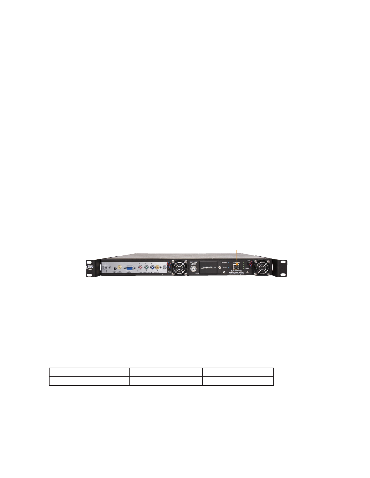
4.10.1 Ethernet Port
A front panel Ethernet network port is provided on the DigiVu Mini 1RU version. The DigiVu 3RU versions both have the
Ethernet port on the back panel. This port is to allow local and remote access to the equipment over the internet or a private
intranet.
Information about use of the Ethernet port may be found at:
Setting port IP addresses “Network Settings” on page 9-6
“Connecting to the Management Computer” on page 5-4
“Connecting to a Local Cable Modem” on page 5-5
The Ethernet port is DTE, similar to a PC Ethernet port and will require a crossover cable to connect to a PC. Connection to a
router or switch may be made with a standard straight through cable. Port speed is 10/100 Base-T and will auto negotiate the
connection based on the fastest common speed of the DigiVu and connected equipment.
4.10.2 Ethernet Cable Type
Ethernet Management Port
Figure 4-3: Management Port on the DigiVu® Mini
Connect DigiVu® to: Router or Switch Computer
Cable Type Straight Through Crossover
Cables of high quality meeting Cat5e or Cat6 are recommended. A crossover cable is supplied with every DigiVu unit.
4.11 Installing Modules
For information on removing or installing modules, see “Field Replacement of Plug-in Cards” on page 13-2.
DigiVu® Series Multichannel MPEG-2/H.264 Encoder/Multiplexer with QAM &/or IP Output - Installation & Operation Manual 4-5
Page 30

CHAPTER 4: INSTALLATION
This page intentionally left blank
4-6 DigiVu® Series Multichannel MPEG-2/H.264 Encoder/Multiplexer with QAM &/or IP Output - Installation & Operation Manual
Page 31
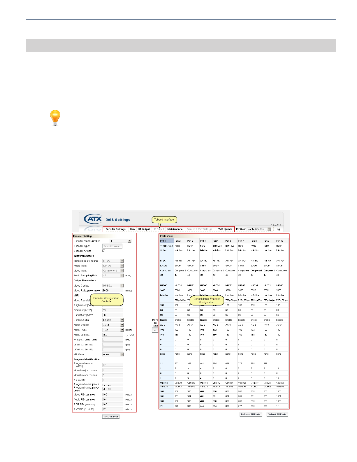
THE GUI
5. The GUI
The DigiVu has many congurable settings which allow customizing of the product to the installation environment. Access to
the DigiVu conguration, referred to as the GUI, is via an integrated web server so a web browser may be used to view and
change settings. The GUI may be accessed remotely over the internet or any private intranet if such access is made available.
FYI: In this guide, reference to DigiVu infers DigiVu 3RU, DigiVu CD 3RU and DigiVu Mini 1RU
unless the model is specically stated. Reference to DVIS is synonymous with DigiVu as these
products run on the same rmware.
5.1 Chapter Contents
• “Conguration Pages”
• “Minimum Computer Requirements”
• “Connecting to the GUI”
• “Connecting to the Management Computer”
• “Connecting to a Local Cable Modem”
• “Factory Default IP Address Settings”
• “Default Username and Password”
• “Resetting the Username and Password”
.
CHAPTER 5: THE GUI
Figure 5-1: The GUI
DigiVu® Series Multichannel MPEG-2/H.264 Encoder/Multiplexer with QAM &/or IP Output - Installation & Operation Manual 5-1
Page 32
CHAPTER 5: THE GUI
5.2 Conguration Pages
5.2.1 Summary of Page Functionality
A brief outline and description of the GUI main conguration tabs follows:
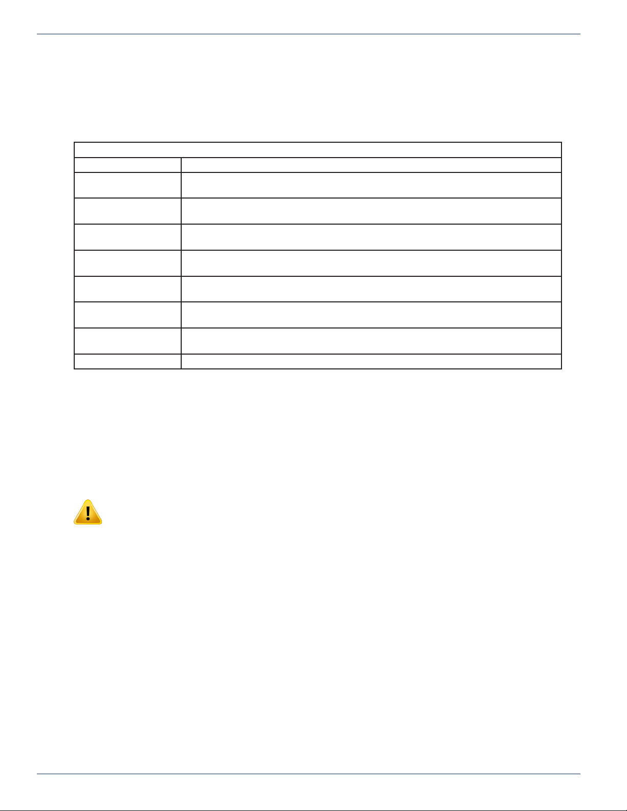
Tab Name Page Properties
“Encoder Settings” Displays the HD/SD MPEG-2/H.264 Encoder congurable settings and the Ports View which
is the complete list of installed modules and their stored conguration.
“Mux” Displays the congurable settings affecting the output multiplex for RF or Ethernet, activation
of the Ethernet output card and settings affecting legacy STB.
“RF Output” Displays the congurable settings affecting the QAM output type and frequency and RF
output level.
“IP Output” Displays congurable settings affecting the Gigabit Ethernet card IP output type, IP source
and destination addressing including VLAN and FEC. Only active with GbE card installed
“Maintenance” Displays congurable settings for the GUI Ethernet network, cooling status and facilitates
exporting congurations for backup and mass deployment.
“Demod & Mux
Settings”
“DVIS Update” Facilitates importing of rmware updates as well as import of a previously exported
Log Used for troubleshooting by ATX Networks support engineers.
Displays congurable settings affecting the demod input frequency and all add/drop
conguration and MPEG stream analyzer controls. Only active with demod card installed.
conguration le.
GUI Conguration Tabs
Figure 5-2: Description of Conguration Tabs
5.3 Minimum Computer Requirements
The computer used to access the DigiVu conguration settings is referred to as the Management Computer. It is recommended
that the Management Computer meet the minimum requirements listed below. ATX Networks does not endorse the use of any
specic operating system software however the listed combination of software has been thoroughly tested with the DigiVu
and is known to work without issue. The operator is free to utilize whatever software combination is desired, however the
responsibility to ensure correct operation of the alternate software is his/hers alone.
NOTE: The extensive use of Java script in the DigiVu interface may cause web browsers other
than Internet Explorer® to incorrectly or incompletely display DigiVu web pages.
5.3.1 Recommended Computer
• Computer running Windows® or other OS.
• Ethernet Network port available.
• Web browser.
• Adobe® Reader® for reading this manual.
5.4 Connecting to the GUI
Conguration of the DigiVu requires a laptop or desktop PC running Microsoft Windows or other OS with an available Ethernet
network port (the Management Computer). If connecting directly to the unit, the Management Computer must be set to operate
on the same subnet as the DigiVu for access to the DigiVu GUI.
The following procedures are for Microsoft Windows XP and a default IP address setting on the DigiVu of 192.168.0.23.
5-2 DigiVu® Series Multichannel MPEG-2/H.264 Encoder/Multiplexer with QAM &/or IP Output - Installation & Operation Manual
Page 33
CHAPTER 5: THE GUI
FYI: If you are using a different Operating System or the network address on the DigiVu has been
changed from default, adjust the procedures to suit the address or software you are using.
1. Connect the Management Computer’s Ethernet adapter to the DigiVu’s Ethernet port using a Cat5e cable, see Figure
5-6. Link lights should illuminate indicating that the cable connection is correct and working.
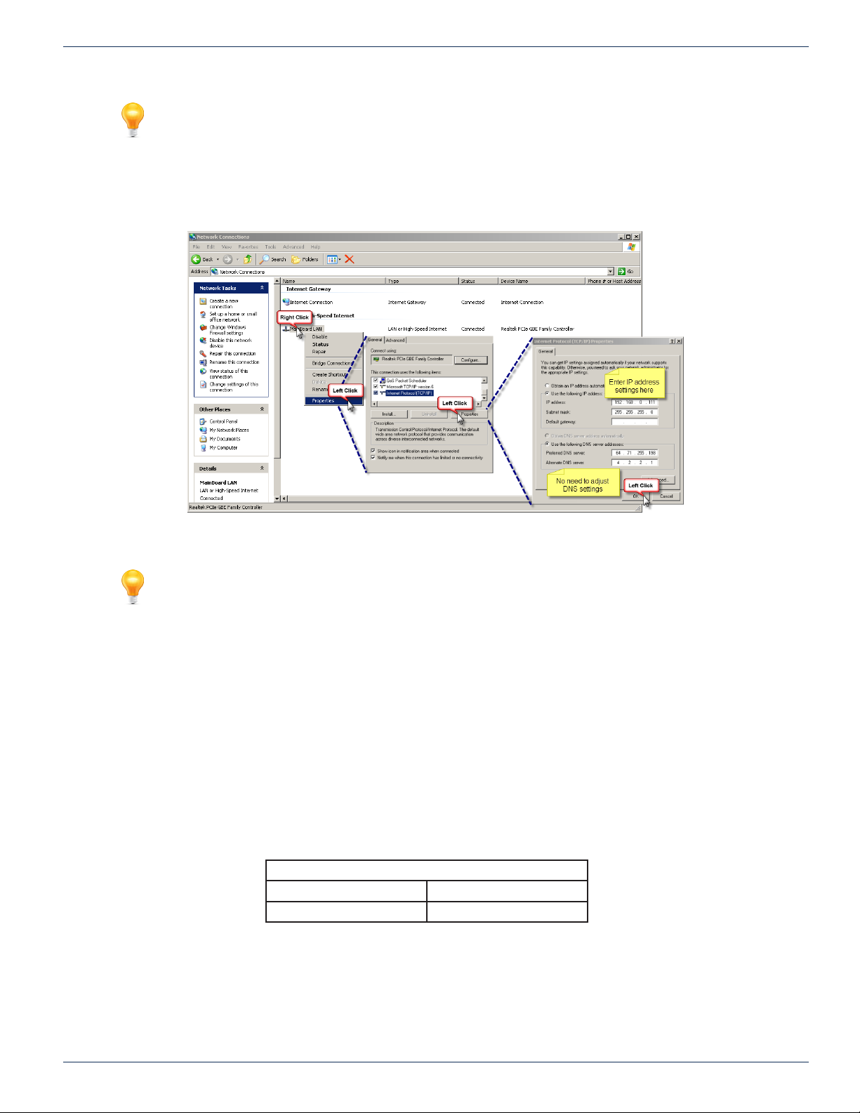
2. Set the Management Computer’s Ethernet interface to a static IP address on the 192.168.0.x subnet, as described
in Figure 5-3.
Figure 5-3: Setting the Management Computer IP Address
FYI: If the Management Computer currently has network settings that will need to be used again
after the DigiVu system is congured, this would be a good time to makes note of the current
settings if you don’t already know them, so the network adapter may be readily returned to these
values again.
a) From the Control Panel, open ‘Network Connections’ and select the connection associated with the
wired Ethernet adapter to be used for connecting to the DigiVu (e.g., Local Area Connection).
b) Right click on the connection then select Properties.
c) Select ‘Internet Protocol (TCP/IP)’ and click Properties.
d) Click the selection box beside Use the following IP address.
e) In the ‘IP address’ eld, enter 192.168.0.x (where x represents any number from 1-253 except 23).
f) Click in the ‘Subnet mask’ eld and the subnet 255.255.255.0 is automatically entered.
g) Click OK and then OK again in the previous window.
3. On the Management Computer, open a web browser and enter http://192.168.0.23/site in the address eld.
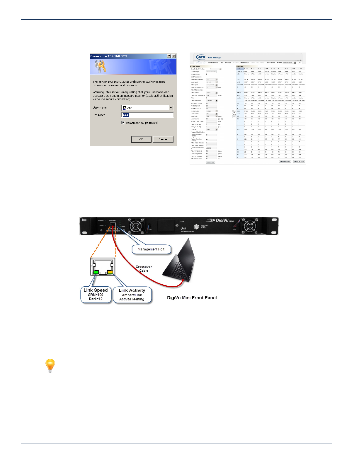
4. You should get the window shown in Figure 5-4 or similar depending on browser, requesting the username and
password.
Default Username and Password
Username Password
atx atx
6. Once logged in you receive the default DigiVu Settings page, shown in Figure 5-5.
DigiVu® Series Multichannel MPEG-2/H.264 Encoder/Multiplexer with QAM &/or IP Output - Installation & Operation Manual 5-3
Page 34
CHAPTER 5: THE GUI
:
Figure 5-4: Login Dialog
Figure 5-5: Default Page
5.5 Connecting to the Management Computer
The DigiVu and DigiVu CD 3RU chassis are both provided with a 10/100 Base-T Ethernet network port on the rear panel for
the Management Port. The 1RU DigiVu Mini has the port on the front panel, shown in Figure 5-6. This port is for connecting to
the GUI for initial conguration and ongoing monitoring and maintenance.
Figure 5-6: DigiVu® Mini Connected to the Management Computer
The management port is DTE, similar to a PC Ethernet port. A crossover Ethernet cable, provided with the equipment on
shipment, will be required to connect the Ethernet port directly to a PC.
The network port will automatically negotiate a speed of 10 or 100 Mbps depending on the capabilities of the PC network port.
A light next to the DigiVu Ethernet port will illuminate amber when a link is negotiated.
FYI: If connectivity problems between the PC network port and the DigiVu occur, (Ethernet link
light does not illuminate) check to be sure that you are using a known good network cable.
If the equipment is to be connected to a local cable modem for remote conguration or monitoring, a standard Cat5e or better
type cable will be required for the connection to the modem. The cable required for connection to the cable modem is normally
supplied with the modem.
5-4 DigiVu® Series Multichannel MPEG-2/H.264 Encoder/Multiplexer with QAM &/or IP Output - Installation & Operation Manual
Page 35
5.6 Connecting to a Local Cable Modem
The following procedure allows remote management using a cable modem for internet connectivity.
5.6.1 Install and Connect the Modem
1. Connect the cable modem RF input to a source of cable TV RF signals of the appropriate level.
2. Verify that the modem completes registration to the DOCSIS carriers (LED indication). If the cable modem does not
lock into the DOCSIS carriers, verify that the signal at the RF input port is sufcient.
5.6.2 Log into the GUI
It is rst necessary to connect the Management Computer directly through a crossover network cable to the front or back panel
management port depending on the model, and congure the DigiVu IP address for remote management. See “Connecting to
the GUI” on page 5-2 for details on logging into the GUI.
5.6.3 Congure the DigiVu® IP Address for Remote Management
CHAPTER 5: THE GUI
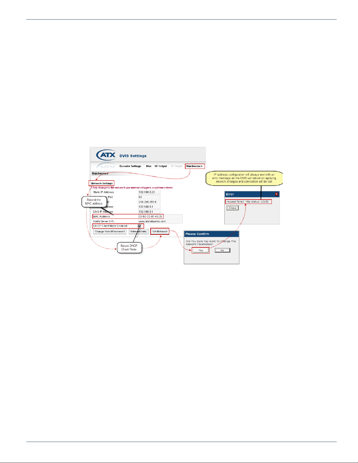
Figure 5-7: Conguring Management Ethernet for DHCP
DHCP IP Address Acquisition from Cable Modem
1. Click the ‘Maintenance’ tab and navigate to the ‘Network Settings’ section.
2. Record the DigiVu Ethernet adapter’s MAC Address for future reference.
3. Select the check box marked ‘DHCP Client Mode Enabled’ and then click Set Network.
4. In the conrmation window that appears, click Yes to conrm the change to the network parameters.
5. The unit will reboot and fans will shut down then restart.
6. An error messages will be displayed in the browser. If Internet Explorer is being used, a message box displaying
request failed. http status 12152 for 1 second then another error message. The error message indicates that the
DigiVu IP address has been modied and therefore connectivity has been lost.
7. Unplug the crossover cable from the DigiVu GUI Ethernet port and connect a straight through Ethernet cable between
the cable modem and the DigiVu Ethernet port.
8. The cable modem LED indicating a valid data connection to a client should light and after approximately 30 seconds
the DigiVu should obtain an IP address from the cable modem.
9. If the cable modem internal DHCP server has assigned the DigiVu an IP address, then open the cable modem web
interface and nd the IP address that was assigned. If the IP address is assigned by the headend DHCP server then
look in the headend DHCP server for the IP address assigned to the MAC address of the DigiVu.
10. Wait 2 minutes then open a new browser session with the GUI using the new IP address that was assigned.
DigiVu® Series Multichannel MPEG-2/H.264 Encoder/Multiplexer with QAM &/or IP Output - Installation & Operation Manual 5-5
Page 36

CHAPTER 5: THE GUI
5.6.4 Static IP Address Assignment
If the DigiVu can be plugged directly into an Ethernet based device, a router, switch, cable modem, that supports clients with
public static IP addresses (or static IP addresses that may be routed to the public internet), the following procedure can be
taken to assign a static IP address.
1. Open the ‘Maintenance’ tab in the GUI and scroll to the ‘Network Settings’ section.
Figure 5-8: Conguring Management Ethernet for Static IP Address
2. Fill in the following elds with appropriate values:
◦ Static IP Address - An IP address assigned to the unit by the network administrator.
◦ Subnet Mask - The mask to match the IP address assigned to the unit by the network administrator.
◦ Default Gateway - The IP address of the router assigned by the network administrator.
3. Click ‘Set Network’.
4. In the conrmation window that appears, click ‘Yes’ to conrm the change to the network parameters.
5. The unit will reboot and fans will shut down, then restart.
6. An error message will be displayed in the browser. If Internet Explorer is being used, a message box displaying
request failed. http status 12152 for 1 second then another error message. The error messages indicate that the
DigiVu network settings have been modied and therefore connectivity has been lost.
7. Wait 2 minutes then open a new browser session with the GUI using the new IP address that was entered.
5.6.5 Connecting Remotely
In order to connect to the DigiVu chassis remotely you need the IP address that the network port has been set to. Depending
on the method of setting the IP address, acquire the address in the following ways. If you know the address skip to “5.6.4 Static
IP Address Assignment” on page 5-6.
5.6.6 Dynamic IP Address Acquired via Cable Modem
In order to reconnect to the GUI after it is connected to a cable modem, it is necessary to determine the IP address the unit
has acquired from the DHCP server. There are two ways to achieve this:
• Get it from the DHCP Server:
Log into the appropriate billing system interface and access the account associated with the cable modem being
used. The account can typically be found by searching according to cable modem MAC address, which is labeled
on the modem. Once you can access the cable modem account, verify that a client with the MAC address noted
above, see the section “5.6.3 Congure the DigiVu® IP Address for Remote Management” on page 5-5 is listed as
connected in the cable modem client table. Record the IP address assigned to the DigiVu unit MAC address in the
cable modem client table.
• Get it from the Cable Modem:
Log into the cable modem interface if it is accessible. Each cable modem has a built-in web server to allow
troubleshooting and this interface will display the acquired IP address.
5-6 DigiVu® Series Multichannel MPEG-2/H.264 Encoder/Multiplexer with QAM &/or IP Output - Installation & Operation Manual
Page 37
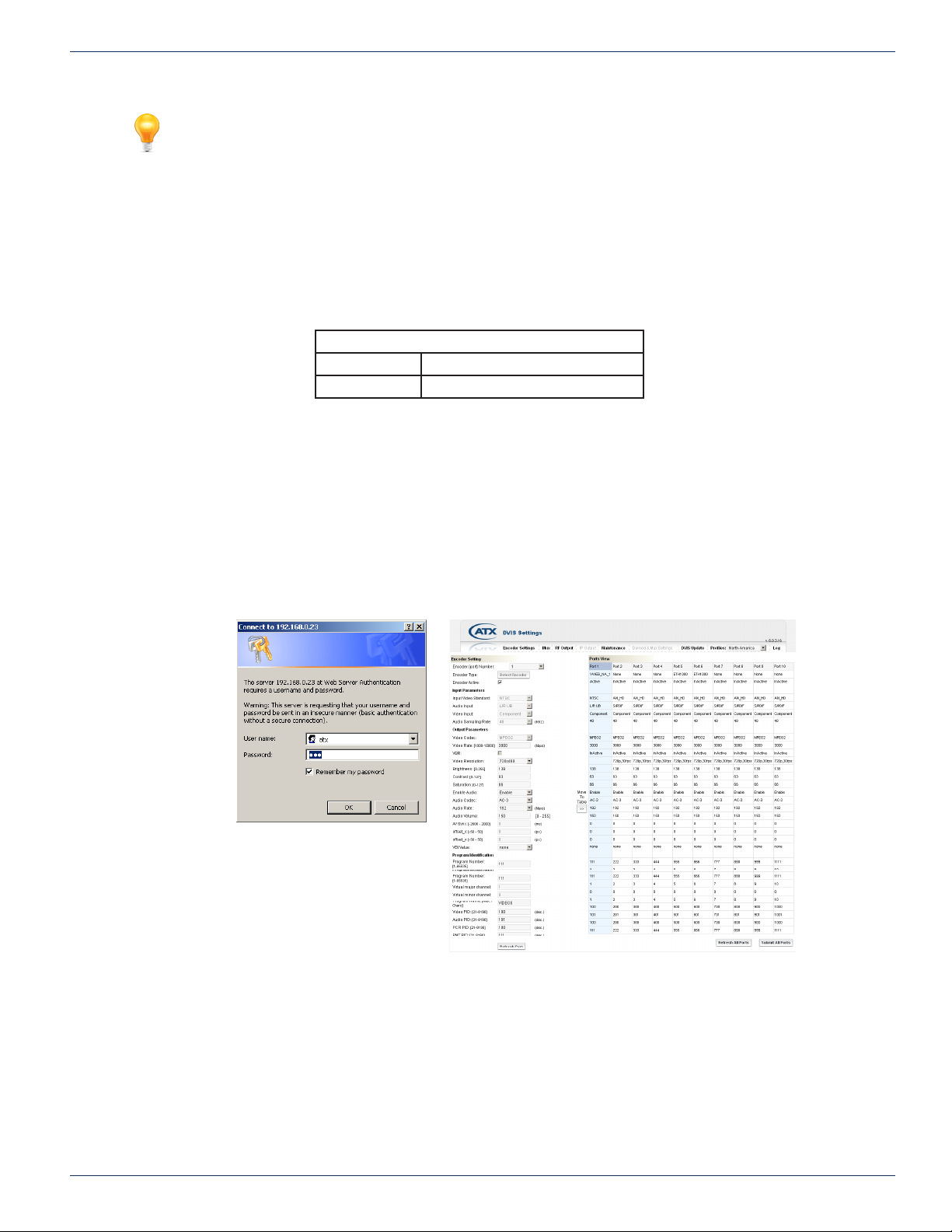
FYI: In some systems, the time for the billing or modem management system to update with the
most recent cable modem client table information may take a few minutes to a few hours. If you
have alternative means to nd out the IP address assigned to the client with the DigiVu MAC
address more rapidly, you can save time as the DigiVu is available for remote access as soon as
the new IP address is acquired, regardless of whether the billing or modem management system
has this information.
Once you have the assigned public IP address of the DigiVu:
1. Open an Internet Explorer web browser and in the address bar enter ‘http://xxx.xxx.xxx.xxx/site’ replacing the x’s with
the IP address of the unit.
2. When the login screen appears, enter the Username and Password for the unit.
Username Password
3. Upon validation of the login and password, the GUI opens and displays the ‘DVIS Settings’ page. The unit is ready
to be managed remotely.
5.6.7 Static IP Address Assigned
1. Login to a computer with internet access. If you are using the same computer that was used for direct connection to
the DigiVu, remember to restore the computer’s network settings to the appropriate values (the settings used prior to
changes made for connection to the DigiVu or other settings, as appropriate).
2. Open a new Internet Explorer browser window to establish a fresh internet session entering the IP address of the
DigiVu GUI in the address window.
3. You should be presented with the following screen on the left, prompting you to log in:
CHAPTER 5: THE GUI
Factory Default Username and Password
atx atx
Figure 5-9: Prompt for
Username & Password
Figure 5-10: Default Screen when Logged In
When the login screen, above left, appears prompting you to log in, enter an appropriate User Name and Password for the
unit from the table below. When the login username and password are successfully entered, the default screen, above right,
will be presented.
DigiVu® Series Multichannel MPEG-2/H.264 Encoder/Multiplexer with QAM &/or IP Output - Installation & Operation Manual 5-7
Page 38
CHAPTER 5: THE GUI
5.7 Factory Default IP Address Settings
The GUI is web based and will require a locally connected computer to complete the conguration. The network port through
which access to the web server is available has been factory pre-congured with the following network settings. By default,
the IP address mode is static IP; DHCP is disabled.
FYI: When entering the default IP address of the DigiVu in a web browser, always be sure to
enter 192.168.0.23/site or xxx.xxx.xxx.xxx/site replacing your unit’s IP address in place of the x’s
Factory Default IP Addresses
IP Address 192.168.0.23
Subnet Mask 255.255.255.0
Web Server Port 80
Gateway 192.168.0.1
5.8 Default Username and Password
Factory Default Username & Password
Username Password
atx atx
FYI: If the DigiVu equipment has previously been congured with a different Username and
Password, use the appropriate values for this unit. When the Username and Password are changed
in the unit, the factory default values are lost. Contact ATX Technical Support for reverting
username/password to default values.
5.9 Resetting the Username and Password
If the Username or Password have been changed and subsequently forgotten, a rmware reset le is available which can
workaround this problem without loss of programmed conguration. Contact ATX Networks for assistance then see “12.9
Username & Password Reset Process” on page 12-8 for a description of the process.
5-8 DigiVu® Series Multichannel MPEG-2/H.264 Encoder/Multiplexer with QAM &/or IP Output - Installation & Operation Manual
Page 39
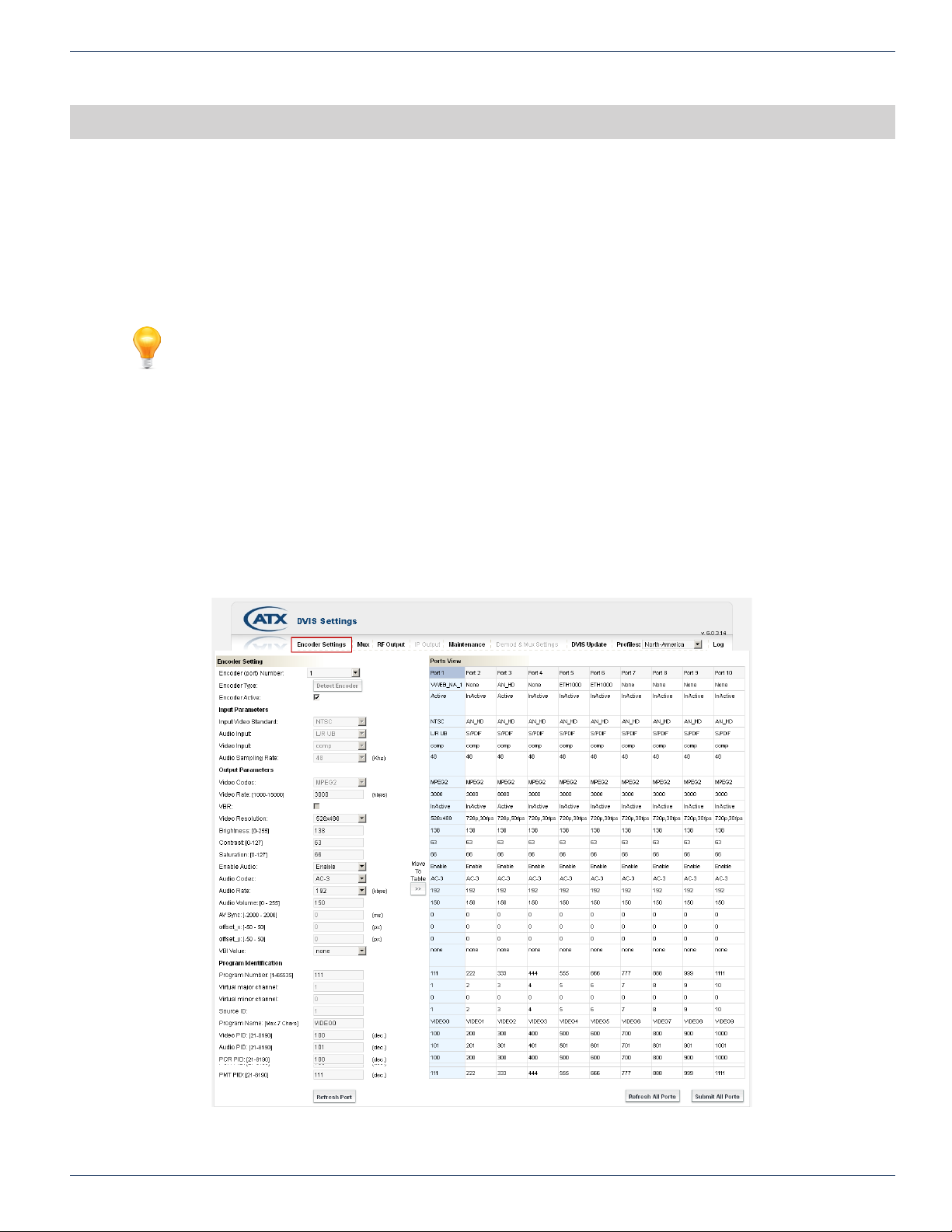
ENCODER SETTINGS TAB
6. Encoder Settings Tab
In this chapter we detail the conguration controls which are used to adjust settings to achieve the encoder performance that
is required. All GUI settings are discussed along with limits and some suggestions as to what values are most applicable
and why. With the selection of some encoder types it will be seen that some parameters are greyed out, meaning that these
parameters are either not relevant or are preset. Reference to DigiVu infers both DigiVu and DigiVu Mini unless specically
stated.
FYI: In this guide, reference to DigiVu infers DigiVu 3RU, DigiVu CD 3RU and DigiVu Mini 1RU
unless the model is specically stated. Reference to DVIS is synonymous with DigiVu as these
products run on the same rmware.
6.1 Chapter Contents
• “SD Encoder Cards”
• “HD Encoder Card”
• “Input and Output Cards”
• “Encoder Settings Tab”
• “Encoder Conguration Quick Guide”
• “Input Parameters”
• “Output Parameters”
• “Program Identication”
CHAPTER 6: ENCODER SETTINGS TAB
Figure 6-1: Encoder Settings Tab
DigiVu® Series Multichannel MPEG-2/H.264 Encoder/Multiplexer with QAM &/or IP Output - Installation & Operation Manual 6-1
Page 40
CHAPTER 6: ENCODER SETTINGS TAB
6.2 SD Encoder Cards
There are three types of SD encoder available, briey described below. The selection of encoder card is principally based on
functionality required. The type of hardware encoder that is plugged in will automatically be detected and reported in the GUI.
The options presented to be congured will be adjusted to only those available to the specic installed encoder.
6.2.1 NXP
• Available as single and dual channel encoder card.
This is the legacy SD MPEG-2 encoder model for both ETSI (European standard) and ATSC (North American standard).
It is no longer available for purchase but may be encountered in existing installations. This encoder supported fewer video
resolutions and audio bit rates than the current VWEB encoder. It also did not support Closed Captioning.
6.2.2 DV1CE & DV2CE
• Available as single and dual channel encoder card.
This is the currently shipping ATSC SD MPEG-2 encoder with support for a wide array of video resolutions and AC-3 audio bit
rates. There is support for ATSC closed captioning which may be turned on or off as required.
6.2.3 DV1CEM & DV2CEM
• Available as single and dual channel encoder card.
This is the currently shipped PAL SD MPEG-2 encoder with support for a wide array of video resolutions and MPEG-1 audio
bit rates.
6.3 HD Encoder Card
There is a single channel HD encoder available. The type of hardware encoder that is plugged in will automatically be detected
and reported in the GUI. The options presented to be congured will be adjusted to only those available to the specic installed
encoder.
6.3.1 DV1HDA
• Available as single channel encoder card only.
This single program HD/SD encoder supports both MPEG-2 or H.264 encoding. The following table outlines the multiplexing
capabilities for HD encoded programs per QAM channel or IP multiplex.
FYI: It is important to note that the Video Resolution of this card must be set to match the input
source.
FYI: The ability to output 5 HD programs per QAM depends on encoding format and bit rate. The
DigiVu and DigiVu CD may be limited to just 2 HD programs per QAM with a high encoder bit rate
setting.
Maximum Programs Encoded per Platform
Platform QAM Output IP Output
DigiVu® 3RU 5 HD Programs 4 HD Programs
DigiVu® CD 3RU 5 HD Programs 4 HD Programs
DigiVu® Mini 1RU 2 HD Programs 1 HD Program
6.4 Input and Output Cards
There are other cards available that may be used for some specialty applications. The cards are briey described below.
6.4.1 DVDMQMB & DVDMQMAC QAM Demodulator
This card must be used if an add/drop conguration is required. May be installed in any card slot except #1.
6.4.2 DVGIGE Gigabit Ethernet Output
This card is used in applications where Ethernet output of the DigiVu is required and is supported only in specic slots. The
recommended slot to use is always the highest available which will usually be slot #2 in the DigiVu Mini 1RU model and slot
6-2 DigiVu® Series Multichannel MPEG-2/H.264 Encoder/Multiplexer with QAM &/or IP Output - Installation & Operation Manual
Page 41
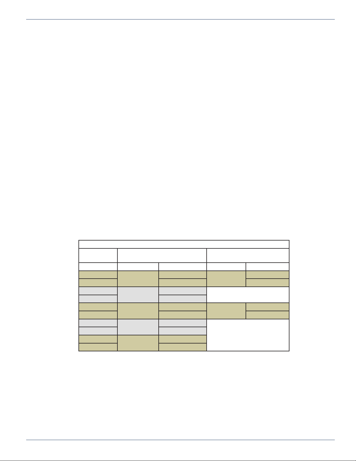
#5 in the DigiVu and DigiVu CD 3RU models.
6.4.3 DV1HDA Distribution Amplier/ 2-Way Baseband A/V Splitter
The splitter is used in applications where only one video/audio source is available but two encoders or one encoder and one
analog RF modulator must be fed by the same source. This splitter creates two baseband A/V outputs from one input. This
may be used in any available slot but should be installed in the AUX slot in the DigiVu and DigiVu CD 3RU models. The splitter
card is an un-managed card (no settings to be adjusted or changed in the GUI) and only requires power and that is the purpose
of the AUX slot.
6.5 Encoder Settings Tab
This page displays the conguration of all of the installed HD/SD MPEG-2/H.264 video/audio encoders and allows adjustment
of the currently set values. If other types of cards are installed, such as a demod or gigabit Ethernet card, they will be reported
under the heading “Encoder Type” but are not congurable on this page, so ignore the settings reported below these cards.
The Encoder Number control is used to select the encoder that is desired to change the settings for, then as each encoder
is selected by way of the drop down dialog box, the appropriate encoder port is highlighted in the Ports View. The general
process for making changes to an encoders settings is as follows:
6.5.1 Port Numbering Convention
DigiVu 3RU Models
Each DigiVu physical encoder slot is assigned a pair of port numbers in the GUI and there can be up to two encoders per
installed card. The rst physical slot is assigned ports 1 & 2, the second slot is assigned ports 3 & 4 etc. If an encoder card has
only one encoder installed, the port that would have been occupied by the second encoder is reported in the GUI as “None”.
DigiVu Mini 1RU
The Mini is slightly different than the 3RU models in that the second physical card slot is associated to the GUI ports 5&6.
This is for support of the DVGIGE card that is not supported in Ports 3&4. In this case, ports 3&4 will be reported in the GUI
as “None”. If a DVGIGE card is installed in a 1RU model, it would always be installed in slot 2.
CHAPTER 6: ENCODER SETTINGS TAB
The following table illustrates the relationship between slots and ports for both the 3RU and 1RU models:
Port Numbering Convention
Port Number
in GUI
Single Encoder Dual Encoder Single Encoder Dual Encoder
Port 1
Port 2 Slot 1 – Input B Slot 1 – Input B
Port 3
Port 4 Slot 2 – Input B
Port 5
Port 6 Slot 3 – Input B Slot 2 – Input B
Port 7
Port 8 Slot 4 – Input B
Port 9
Port 10 Slot 5 - Input B
Physical Card Slot
DigiVu® / DigiVu® CD
Slot 1
Slot 2
Slot 3
Slot 4
Slot 5
Slot 1 – Input A
Slot 2 – Input A
Slot 3 – Input A
Slot 4 – Input A
Slot 5 - Input A
Physical Card Slot
DigiVu® Mini
Slot 1
Ports 3&4 show up in GUI but there is
no physical associated slot.
Slot 2
Ports 7-10 show up in GUI but there
are no physical associated slots.
Slot 1 – Input A
Slot 2 – Input A
DigiVu® Series Multichannel MPEG-2/H.264 Encoder/Multiplexer with QAM &/or IP Output - Installation & Operation Manual 6-3
Page 42
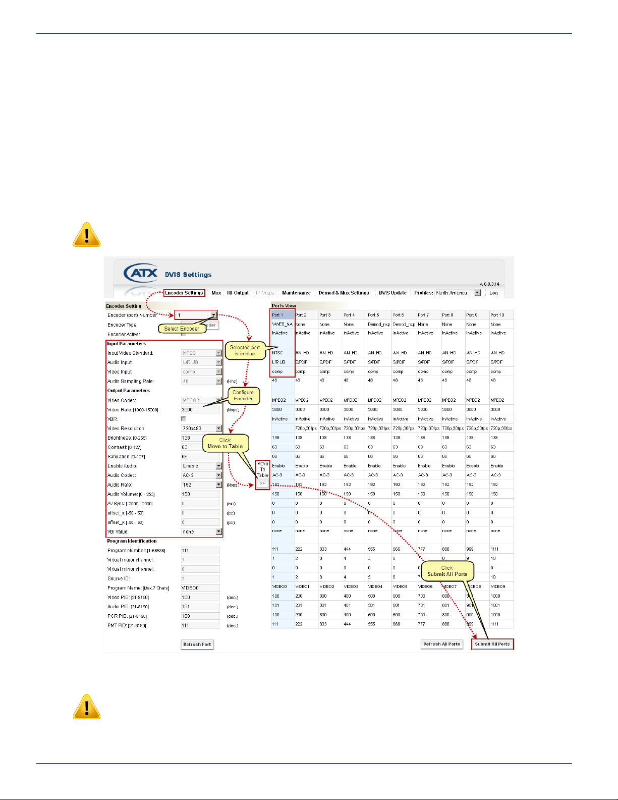
CHAPTER 6: ENCODER SETTINGS TAB
6.6 Encoder Conguration Quick Guide
6.6.1 Quick Guide to Encoder Conguration:
Refer to Figure 6-2 for clarication of this procedure.
1. Select the encoder port number that represents the encoder that is desired to be congured from the drop down box
labeled ‘Encoder (port) Number:’
2. Make any adjustments required for the selected encoder in each of the dialogs or drop downs in the left column.
3. Click Move to Table. This stores the changes for the selected encoder but does not apply the settings.
4. Repeat from step 2 for each encoder requiring conguration.
5. When all encoders have been congured as needed, click Submit All Ports to apply all of the settings changes
simultaneously.
NOTE: The result of clicking ‘Submit All Ports’ is service affecting.
Figure 6-2: Quick Guide to Encoder Conguration
NOTE: When operating in Add & Drop Mode, a number of encoder settings on this screen are
greyed out as they are set elsewhere. See “Demod & Mux Settings” on page 10-4.
6-4 DigiVu® Series Multichannel MPEG-2/H.264 Encoder/Multiplexer with QAM &/or IP Output - Installation & Operation Manual
Page 43
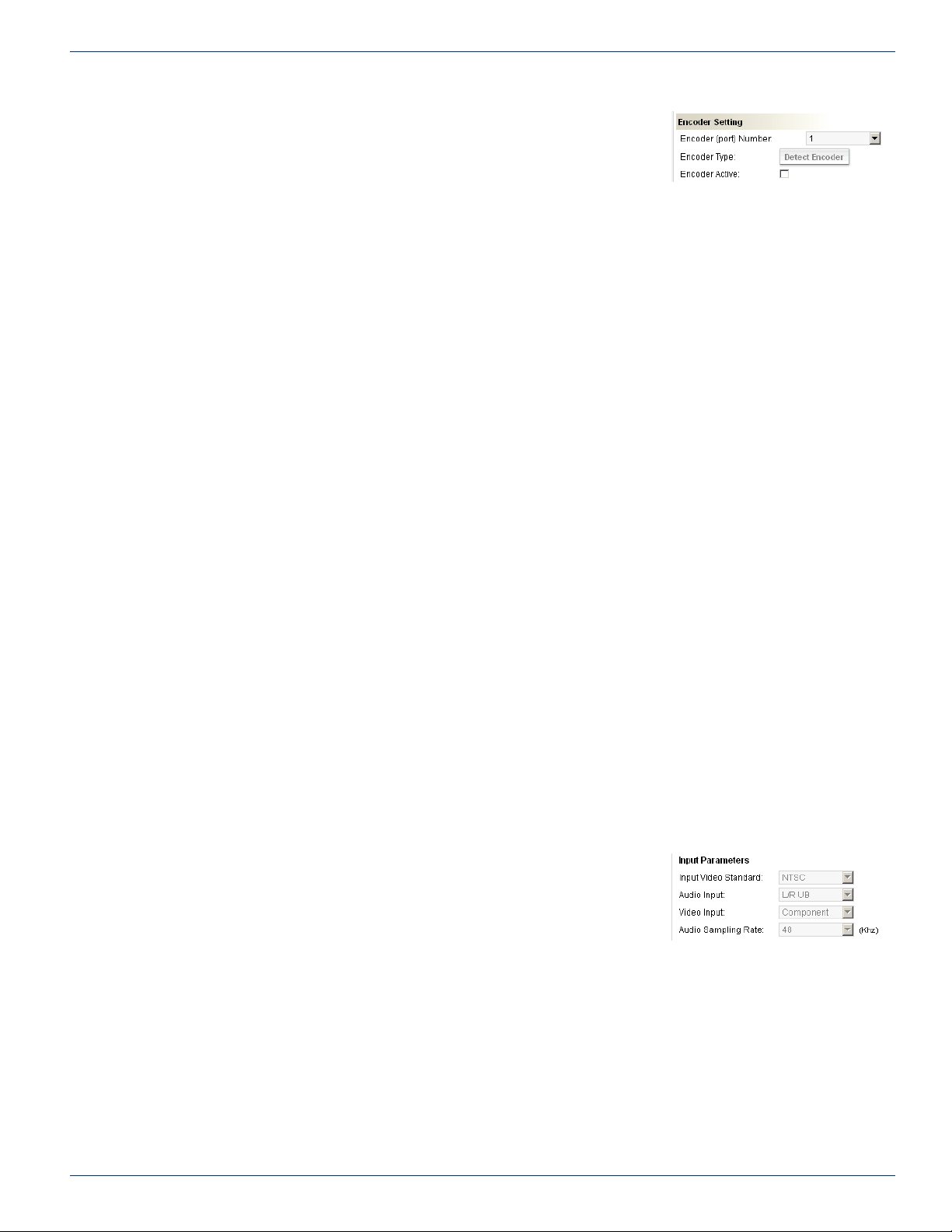
6.7 Encoder Setting
6.7.1 Encoder (port) Number:
Select the encoder port number from the drop down box representing the encoder
that you wish to adjust the settings for. The applicable/selected column becomes
highlighted in Ports View.
6.7.2 Encoder Type:
In the ‘Ports View’ section, the type of encoder installed is indicated. The types of SD encoders that may be encountered here
were discussed in “SD Encoder Cards” on page 6-2 as well as the type of HD encoder in “HD Encoder Card” on page 6-2.
If another type of card is installed this will also be identied. These cards were briey discussed in section “Input and Output
Cards” on page 6-2. Disregard the conguration reported for all cards except encoders. The possible card types that may
be reported here are:
• VWEB_NA (NTSC Video SD MPEG-2, AC-3 audio)
• VWEB_NA_1 (NTSC Video SD MPEG-2, AC-3 audio)
• VWEB_EU (PAL Video SD MPEG-2, MPEG-1 L2 audio)
• VWEB_EU_1 (PAL Video SD MPEG-2, MPEG-1 L2 audio)
• NXP (Legacy NTSC/PAL Video MPEG-2 w/AC-3 & MPEG1 audio)
• ETH1000 (GigE Output Card)
• AN_HD (HD/SD MPEG-2/H.264 encoding)
• Demod_nxp (Legacy Demod Card)
• Demod_dnq (Demod Card)
CHAPTER 6: ENCODER SETTINGS TAB
Figure 6-3: Encoder Setting
6.7.3 Detect Encoder (Control)
• Slot Previously Empty
If an encoder slot was previously empty and a new encoder card was hot plugged into the slot, the GUI must be
made aware of the change as it will not take any action without instruction. Click the Detect Encoder button to force
a detection of the encoder card just installed. The control will be greyed out on any encoder selected that has already
been detected.
• Slot Previously Occupied
If an encoder slot was previously occupied and a different card was hot plugged into the slot the DigiVu must be made
aware of it but the control is greyed out. In this case, click the Refresh All Ports button at the bottom of the GUI page
to force the DigiVu to detect the encoder card just installed. The control will be remain greyed out on any encoder
selected that has already been detected.
6.7.4 Encoder Active:
This check box lets you switch each encoder on and off. On the right side of the page in the Ports View display, encoders are
shown as active or inactive.
6.8 Input Parameters
This group of settings are for conguration of any input variables on some encoders,
such as Video Input on the HD encoder. Some of these are preset by the GUI
depending on the encoder card and in this case, is for information only.
6.8.1 Input Video Standard:
Automatically selected as NTSC or PAL as appropriate for the SD encoder card
installed. If an HD encoder is installed, this displays AN_HD.
Figure 6-4: Input Parameters
6.8.2 Audio Input:
Selects between input types if more than one is available for the selected card. For the HD encoder the selectable input types
are L/R UB analog audio or S/PDIF. The S/PDIF input supports AC-3 only and PCM is not supported. For the SD encoders
the input type is L/R UB.
DigiVu® Series Multichannel MPEG-2/H.264 Encoder/Multiplexer with QAM &/or IP Output - Installation & Operation Manual 6-5
Page 44
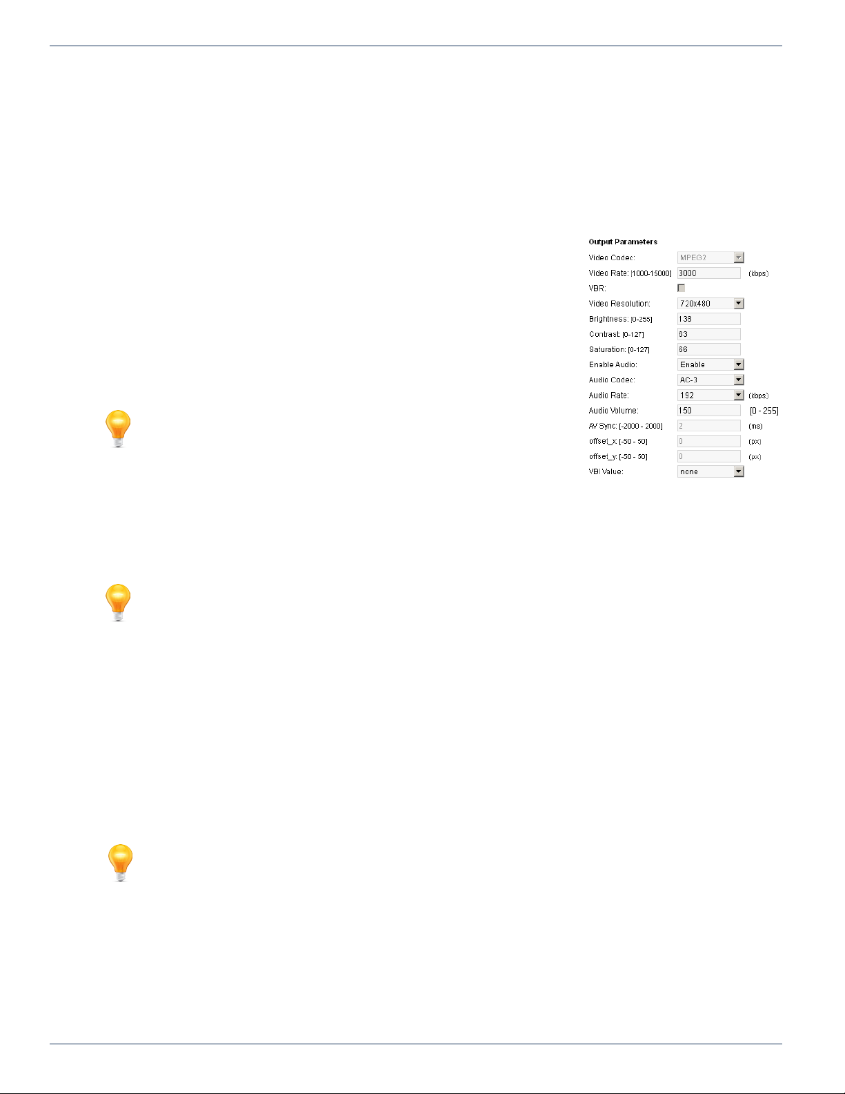
CHAPTER 6: ENCODER SETTINGS TAB
6.8.3 Video Input:
Selects between input types if more than one is available for the selected card. For the HD encoder the input types are VGA ,
and Component. For the SD Encoders the input type is Composite.
6.8.4 Audio Sampling Rate:
This value is preset at 48 kHz and is the number of samples per second (in kHz) taken from an analog signal to make a digital
signal.
6.9 Output Parameters
This group of conguration settings affect the video and audio program stream
properties.
6.9.1 Video Codec:
For encoder cards with more than one type of encoding prole, this allows selection of
the required prole. For the HD encoder card the prole types are MPEG-2 and H.264.
For the SD encoders, the prole is MPEG-2 for ATSC and ETSI.
6.9.2 Video Rate: [1000-20000]
FYI: When the unit is operating in Add & Drop Mode, this setting is
greyed out as it is set in the conguration view “Demod & Mux Settings”
on page 10-4
The video program elementary stream bit rate is entered in kbps and must be between
1000 and 8000 for SD programs, between 1000 and 20000 for H.264 HD programs
and between 1000 and 20000 for MPEG-2 HD programs. Increasing the bit rate
increases the resulting picture quality but consumes more bandwidth. The entered
value must be balanced against the number of other programs in the output MUX and the total amount of room within the MUX
for each program.
FYI: Although the HD resolution support is able to be set as low as 1000 kbps, this low bit rate
will not result in suitable quality and is only intended for the SD resolutions that this HD card
supports. Suitable quality for HD programs will be obtained at a bit rate of 6000 kbps or higher.
6.9.3 VBR:
Not functional at this time. Future implementation.
6.9.4 Video Resolution:
Video resolution refers to the number of discrete picture elements (pixels) in each horizontal line and the number of displayed
horizontal lines in the picture. (e.g. 720 pixels per line x 480 lines). The available video resolution settings depend on the type
of encoder installed. Higher picture resolutions require a higher video bit rate for the same picture quality and conversely,
a lower resolution picture can be encoded with a lower bit rate. Depending on the quality required and the resolution of the
source video, such as a lobby camera, lowering the resolution and bit rate may be used and more channels may be added
in available bandwidth. For all SD encoder cards, the Video Resolution setting determines the output resolution, however, for
the HD encoder card (for HD encoding resolutions), the Video Resolution setting must be set to match the input resolution.
FYI: It is important to note that the Video Resolution of the HD encoder card (for HD encoding
resolutions) must be set to match the input source resolution.
Figure 6-5: Output Parameters
6.9.5 Brightness: [0-255]
This dialog allows modication of the video signal to increase or decrease brightness. There are 256 levels available (0-255)
The default value is preset at 138. This setting should not normally require changing.
6.9.6 Contrast: [0-127]
This dialog allows modication of the video signal to increase or decrease picture contrast. There are 128 levels available (0-
127) The default value is preset at 63. This setting should not normally require changing.
6-6 DigiVu® Series Multichannel MPEG-2/H.264 Encoder/Multiplexer with QAM &/or IP Output - Installation & Operation Manual
Page 45

6.9.7 Saturation: [0-127]
This dialog allows modication of the video signal to increase or decrease color saturation. There are 128 levels available (0-
127) The default value is preset at 66. This setting should not normally require changing. For HD this is not applicable.
6.9.8 Enable Audio:
The audio codec may be disabled if the specic application of the DigiVu does not require an audio program such as a lobby
camera. Disabling the audio codec will result in silence at the receiving TV. Use the drop down box to select the required
setting. The default is Enable.
6.9.9 Audio Codec:
This setting is automatically set to the value appropriate for the detected SD encoder card. A codec converts an audio baseband
signal to a specic streaming audio format. The AC-3 codec supported in DigiVu is 2.0 (two channel stereo). The supported
audio codec depends on the encoder card installed.
6.9.10 Audio Rate:
This drop down displays the audio bit rate options available for each installed encoder. This is the data rate at which an audio
signal is encoded. Each encoder supports commonly used bit rates which range from 192 - 384 kbps. The recommended
audio rate is 192 kbps for stereo audio.
6.9.11 Audio Volume:
This control inuences the volume level of the incoming baseband audio signal into the encoder card. This value typically
does not need to be changed from it’s default value but some guidance is provided if audio volume is not satisfactory with
standard settings.
Setting Audio Volume
• SD Encoder - The scale is 0 - 255 with the default setting of 150.
The value represents a relative volume output and is not an absolute level. If the volume as heard on a TV or other
receiving device is too high or too low, increase the value to increase the output volume or decrease the value to
decrease the output volume. Be careful to not increase the volume excessively as the encoding of extreme high
volumes will cause instability.
• HD Encoder - The scale is in dB with a default setting of 0 dB.
The value represents a relative volume output and is not an absolute level. If the volume as heard on a TV or other
receiving device is too low, increase the setting to a positive number to increase the output volume. An increase of
10 dB will double the output volume. Be careful to not increase the volume excessively as the encoding of extreme
high volumes will cause instability.
CHAPTER 6: ENCODER SETTINGS TAB
6.9.12 AV Sync:
This adjusts audio/video lip-sync up to +/- 2000 ms if program audio is not in synchronization with the video. With each
adjustment of this value, click Add to Table then Submit all Ports for the value to become effective, see Figure 6-2 for
guidance. If needed, the correct value is found by trial and error.
6.9.13 Offset_X:
This setting allows the adjustment of the horizontal position of VGA input signals only. With each adjustment of this value,
click Add to Table then Submit all Ports for the value to become effective, see Figure 6-2 for guidance. The picture may be
shifted by +/- 50 pixels.
6.9.14 Offset_Y:
This setting allows the adjustment of the vertical position of VGA input signals only. With each adjustment of this value, click
Add to Table then Submit all Ports for the value to become effective, see Figure 6-2 for guidance. The picture may be shifted
by +/- 50 pixels.
6.9.15 VBI Value:
This tick box enables Closed Caption (CC) support in the Vertical Blanking Interval (VBI). Only the value appropriate to the
installed encoder will be available in the drop down. The video encoders do not create a closed caption, they capture existing
closed captions on incoming video and convert them to a digital format.
• ATSC_CC Enables the processing CC data for ATSC (In cards VWEB_NA, VWEB_NA_1, DV1HDA).
• ETSI_CC Enables the processing of CC data for the ETSI (not currently implemented).
• NONE Disables the closed caption function.
DigiVu® Series Multichannel MPEG-2/H.264 Encoder/Multiplexer with QAM &/or IP Output - Installation & Operation Manual 6-7
Page 46
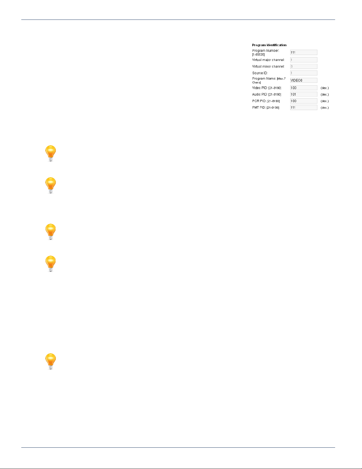
CHAPTER 6: ENCODER SETTINGS TAB
6.10 Program Identication
This section allows conguration of the program specic settings of the MPEG2 transport stream. The PID values may often be left at their default values. The
‘Program Number’ must be set appropriately. The remaining parameters may or may
not need to be set as it is application specic.
6.10.1 Program Number: [1-65535]
This is the MPEG-2 Program Number that identies a program from others within a
multiplex and is used to allow selection and decoding at the receiving device. It is a
unique number that is assigned to each program within a multiplex and may require
setting according to the system channel map. The decoding device may display this
program number for program selection.
6.10.2 Virtual Major Channel:
FYI: For virtual Major/Minor channels to be detected and acted upon by an appropriate end user
device, it is required to enable the ‘PSIP’ feature on the MUX tab. See “7.4 DVB® SI Settings” on
page 7-2 to enable this feature.
FYI: This parameter is only detected or used by end user devices that support PSIP tables.
Figure 6-6: Program Identication
For a program in a QAM channel, this is the major channel which is often also the EIA channel.
6.10.3 Virtual Minor Channel:
FYI: For virtual Major/Minor channels to be detected and acted upon by an appropriate end user
device, it is required to enable the ‘PSIP’ feature on the MUX tab. See “7.4 DVB® SI Settings” on
page 7-2 to enable this feature.
FYI: This parameter is only detected or used by end user devices that support PSIP tables.
For a program in a QAM channel, this is the program number within the previously dened Major channel. This is the program
number within the multiplex.
6.10.4 Source ID:
A source ID may be assigned here if the DigiVu application required it. This is not mandatory.
6.10.5 Program Name: [Max. 12 Chars]
FYI: For Program Name to be detected and acted upon by an appropriate end user device, it is
required to enable the DVB-SI feature on the MUX tab. See “7.4 DVB® SI Settings” on page 7-2
to enable this feature.
The name (up to 12 characters) assigned to a program may be entered here. To enable, it is required to select the DVB-SI
option in MUX page. This name may or may not be supported in the end customer decoding device.
6.10.6 Video PID: [21-8190]
The video PID (Packet Identier) is a decimal number that uniquely identies a video transport stream in an MPEG-2 transport
stream so that it can be ltered and routed appropriately. This value often does not need to be changed from it’s default value
as it is automatically reported in the PMT table.
6-8 DigiVu® Series Multichannel MPEG-2/H.264 Encoder/Multiplexer with QAM &/or IP Output - Installation & Operation Manual
Page 47
6.10.7 Audio PID: [21-8190]
The audio PID (Packet Identier) is a decimal number that uniquely identies an audio transport stream in an MPEG-2
transport stream so that it can be ltered and routed appropriately. This value often does not need to be changed from it’s
default value as it is automatically reported in the PMT table.
6.10.8 PCR PID: [21-8190]
The PCR (Program Clock Reference) PID (Packet Identier) is a decimal number that uniquely identies the time base for
synchronization of individual frames or elds of the video stream and their associated audio. This value often does not need
to be changed from it’s default value as it is automatically reported in the transport stream. Typically it always takes the same
value as the video PID.
6.10.9 PMT PID: [21-8190]
The PMT (Program Map Table) PID (Packet Identier) is a decimal number that uniquely identies a PMT table in an MPEG2 transport stream. The PMT contains a data structure specifying which PIDs carry the video, audio and data stream that
collectively constitute the broadcast program. This value often does not need to be changed from it’s default value as it is
automatically reported in the PAT table.
6.11 Platform Control Buttons
CHAPTER 6: ENCODER SETTINGS TAB
6.11.1 Refresh Port
This control reads the DigiVu stored settings and refreshes the page with the values.
This also will read the encoder card types installed and populate the display with the
discovered types. This is useful when an encoder card type has been changed or a new encoder card installed. This is not a
service affecting operation.
6.11.2 Submit All Ports
NOTE: This is a service affecting operation.
This control applies all of the changes made on the ‘Encoder Settings’ tab and makes the changes part of the working
conguration of the DigiVu system. If changes have been made, click ‘Submit’ button before navigating away from the page,
to avoid all changes being lost. This attribute may be used to throw away changes made if you change your mind.
Figure 6-7: Control Buttons
DigiVu® Series Multichannel MPEG-2/H.264 Encoder/Multiplexer with QAM &/or IP Output - Installation & Operation Manual 6-9
Page 48

CHAPTER 6: ENCODER SETTINGS TAB
This page intentionally left blank
6-10 DigiVu® Series Multichannel MPEG-2/H.264 Encoder/Multiplexer with QAM &/or IP Output - Installation & Operation Manual
Page 49
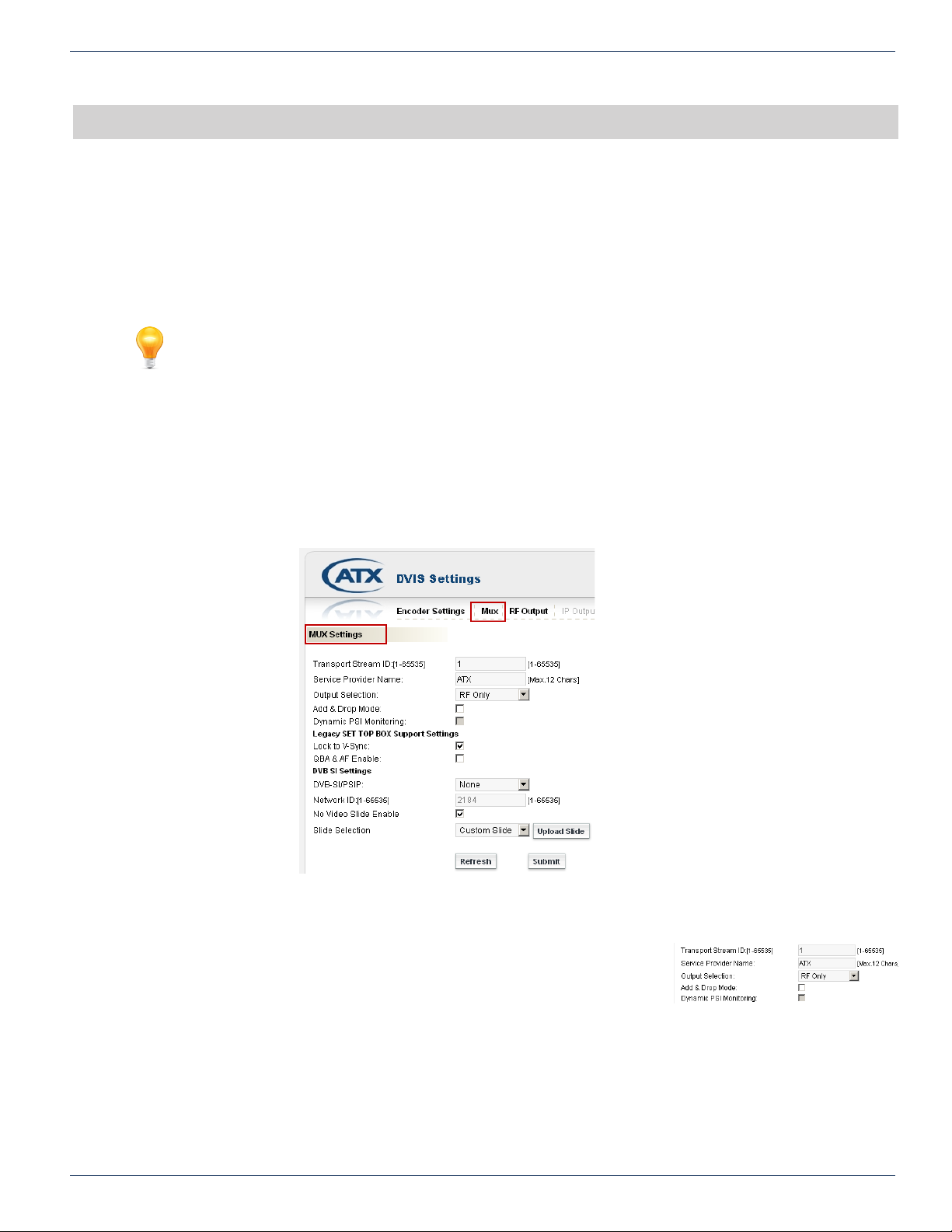
MUX TAB
7. Mux Tab
In this chapter we detail the multiplexer controls for the specic installation environment. All settings are discussed along with
limits and some suggestions as to what values are most applicable and why. If there is a Gigabit Ethernet output card installed,
this is the page where the Ethernet output is enabled. The Ethernet and RF outputs may be exibly set to either RF, Ethernet,
or both simultaneous output types. While the Ethernet output is enabled here, it is not congured on this page. See “IP Output
Tab” on page 11-1 for Ethernet conguration.
FYI: In this guide, reference to DigiVu infers DigiVu 3RU, DigiVu CD 3RU and DigiVu Mini 1RU
unless the model is specically stated. Reference to DVIS is synonymous with DigiVu as these
products run on the same rmware.
7.1 Chapter Contents
• “MUX Settings”
• “Legacy STB Settings”
• “DVB® SI Settings”
• “No Video Slide Enable”
CHAPTER 7: MUX TAB
Figure 7-1: Mux Conguration Tab
7.2 MUX Settings
7.2.1 Transport Stream ID: [1-65535]
A Transport Stream ID is a unique number describing the transport stream. The default
value is 1 and supported values are 1 - 65535.
7.2.2 Service Provider Name:
An optional entry used to identify the provider of the service. This may or may not be supported or displayed by the end
customer decoder device.
DigiVu® Series Multichannel MPEG-2/H.264 Encoder/Multiplexer with QAM &/or IP Output - Installation & Operation Manual 7-1
Figure 7-2: MUX Settings
Page 50

CHAPTER 7: MUX TAB
7.2.3 Output Selection:
This check box selects which outputs are active. Ethernet may not be activated if there is no Ethernet output card installed in
slot 2 or 5. IF SPTS IP output is desired, the only mode this is supported under is ‘Ethernet Only’. The supported selections
are:
• RF Only
• Ethernet only
• RF & Ethernet
FYI: The Ethernet output is enabled here but is congured on the “IP Output Tab”. See “IP Output
Tab” on page 11-1 for further details.
7.2.4 Add & Drop Mode:
This check box selects whether the ‘Demod & Mux Settings’ tab is enabled. The ‘Demod & Mux Settings’ are required if a
demodulator is installed. After activation see “Demod & Mux Settings Tab” on page 10-1. After checking the box click Submit
button to apply the change.
7.2.5 Dynamic PSI Monitoring:
Selects whether Dynamic PSI (Program Specic Information) monitoring is enabled. This will instruct the unit to monitor the
incoming PSI tables for changes and reanalyze the stream when they occur. This feature is active in add/drop mode only.
7.3 Legacy STB Settings
7.3.1 Lock to V-Sync:
The default setting is ‘Lock to Internal Sync’; the check box is not selected. Issues with
vertical sync quality will usually manifest as constant or occasional vertical rolling of
the image. The quality of the baseband vertical sync signal can be impacted by a number of factors including source quality,
cable length, connectors and the presence of distribution amps. Using the internally generated timing signals is usually
the most reliable method of sync recovery but in some circumstances better results maybe achieved by using the external
baseband sync signal if vertical rolling is experienced. In this case click the selection box. This setting is not directly related
to legacy STBs.
7.3.2 QBA & AF Enable:
Selects whether QBA and AF are enabled. Necessary only for some legacy set top boxes. Default; the check box is not
selected.
7.4 DVB® SI Settings
These settings are not always required to be used for typical operation. They provide
additional features if required by system operator.
7.4.1 DVB® -SI/PSIP:
This setting is a drop down menu with preset options.
• None
• DVB-SI
This selection enables support for passing/updating the SDT (Service Description Table) and NIT (Network Information
Table) tables through the multiplexer in a drop & insert application as well as creation of SDT/NIT tables in encoding
mode. It may be necessary in some installations to enable these tables to be received by the end user when tuned to
the DigiVu programs. In add/drop applications the SDT/NIT tables must be existing in the incoming QAM. If the tables
do not exist, do not attempt to enable this feature.
• PSIP
This selection enables insertion of Virtual Channel information as per PSIP standard, see “6.10 Program Identication”
on page 6-8.
Figure 7-3: Legacy STB Settings
Figure 7-4: DVB SI Settings Section
7.4.2 Network ID: [1-65535]
This is the Network ID as listed in NIT.
7-2 DigiVu® Series Multichannel MPEG-2/H.264 Encoder/Multiplexer with QAM &/or IP Output - Installation & Operation Manual
Page 51
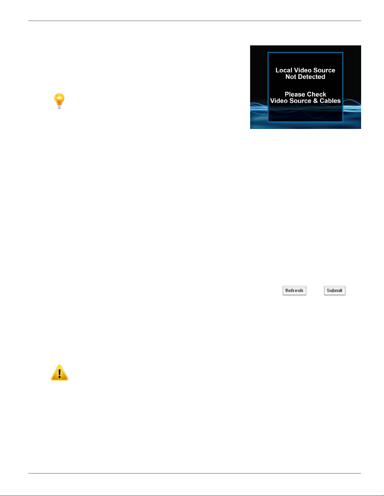
7.5 No Video Slide Enable
This ‘No Video’ feature allows a slide to be shown to the viewer on an SD
channel that loses video input to the encoder card. There is a pre-congured
default slide, Figure 7-5, but a custom slide may also be uploaded to the
system, see “7.5.4 Custom Slides”.
NOTE: This feature is only available for use with SD encoder
cards DV1CE, DV2CE, DV1CEM & DV2CEM. This will not work
with the current HD encoder card.
7.5.1 If Checked
On loss of video to an SD encoder, the DigiVu displays a built-in or custom
slide graphic on the program output of encoders. One slide will display on all
active encoders.
7.5.2 If Not Checked
On loss of video to an SD encoder, the DigiVu will have no output program to display. Depending on end display equipment it
may show up as a black or blue screen or some default screen from end display device.
7.5.3 Built-in Slide
The default built-in slide provided displays a message indicating that a video source is not detected and advises that the video
source and cables should be checked. This feature is useful to avoid blank channels in the lineup when local video sources
fail. It indicates that the DigiVu is functioning and RF output is present indicating that other customer premise equipment
should be checked rst. In some situations this may help prevent unnecessary service calls for the DigiVu platform. Once this
feature is enabled by ticking the box, a menu is activated which allows selection of either the default slide or a custom slide.
CHAPTER 7: MUX TAB
Figure 7-5: Default ‘No Video’ Slide
7.5.4 Custom Slides
Custom SD slides should rst be created using our online tool available in the Resources & Support Section, sub-section
Calculators & Utilities at atxnetworks.com. The web tool is called “Video Loop Creation Tool”. Once the slide is created, it has
to be exported (saved on local PC) and then uploaded into the DigiVu using the ‘Upload Slide’ button. Click the Submit button
to save and apply the image slide settings.
7.6 Platform Control Buttons
7.6.1 Refresh
This control reads the product’s stored settings and refreshes the page with the
values. This also will force the product to read the encoder card types installed and
populate the display with the discovered types. This is useful when an encoder card type has been changed or a new encoder
card installed.
This is not a service affecting operation.
7.6.2 Submit
NOTE: This is a service affecting operation.
This control applies all of the changes made on the ‘Mux’ tab and makes the changes part of the working conguration of the
DigiVu system. If changes have been made click Submit button before navigating away from the page, to avoid all changes
being lost. This attribute may be used to throw away changes made if you change your mind.
Figure 7-6: Platform Control Buttons
DigiVu® Series Multichannel MPEG-2/H.264 Encoder/Multiplexer with QAM &/or IP Output - Installation & Operation Manual 7-3
Page 52

CHAPTER 7: MUX TAB
This page intentionally left blank
7-4 DigiVu® Series Multichannel MPEG-2/H.264 Encoder/Multiplexer with QAM &/or IP Output - Installation & Operation Manual
Page 53
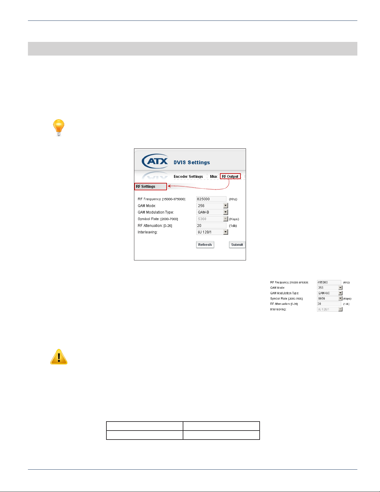
RF OUTPUT TAB
8. RF Output Tab
In this chapter we discuss the RF output conguration. This is the page from which all QAM RF output settings are changed
or congured. Reference to DigiVu infers the discussion applies to DigiVu 3RU, DigiVu CD and DigiVu Mini unless specically
stated.
FYI: In this guide, reference to DigiVu infers DigiVu 3RU, DigiVu CD 3RU and DigiVu Mini 1RU
unless the model is specically stated. Reference to DVIS is synonymous with DigiVu as these
products run on the same rmware.
CHAPTER 8: RF OUTPUT TAB
Figure 8-1: RF Output Conguration Tab
8.1 RF Settings
Settings affecting the QAM RF output of the DigiVu are congured on this page. QAM
output conguration settings and operation is based on ITU-T Recommendation J.83
standards.
8.1.1 RF Frequency: [15000-975000] (kHz)
Enter the required QAM output channel center frequency here in kHz without any
decimals or commas. This supports STD, IRC and HRC channel plans. The limits of tuning are 30 MHz to 960 Mhz.
NOTE: Uniform RF performance (as per published spec) is available between 30 MHz and 960
MHz. The areas close to lowest/highest tunable range fall in the roll-off of the operating range and
RF parameters (for instance MER) are starting to degrade in these two border areas. Depending
on desired application this might or might not be acceptable. It should be tested under such
application to obtain relevant data about suitability.
8.1.2 QAM Mode:
Select the appropriate QAM constellation. The available selection is dependant on the selected QAM modulation type as
outlined below:
North America - QAM-B Europe/Japan - QAM A/C
64 & 256 QAM 16, 32, 64, 128 & 256 QAM
Figure 8-2: RF Settings Section
DigiVu® Series Multichannel MPEG-2/H.264 Encoder/Multiplexer with QAM &/or IP Output - Installation & Operation Manual 8-1
Page 54
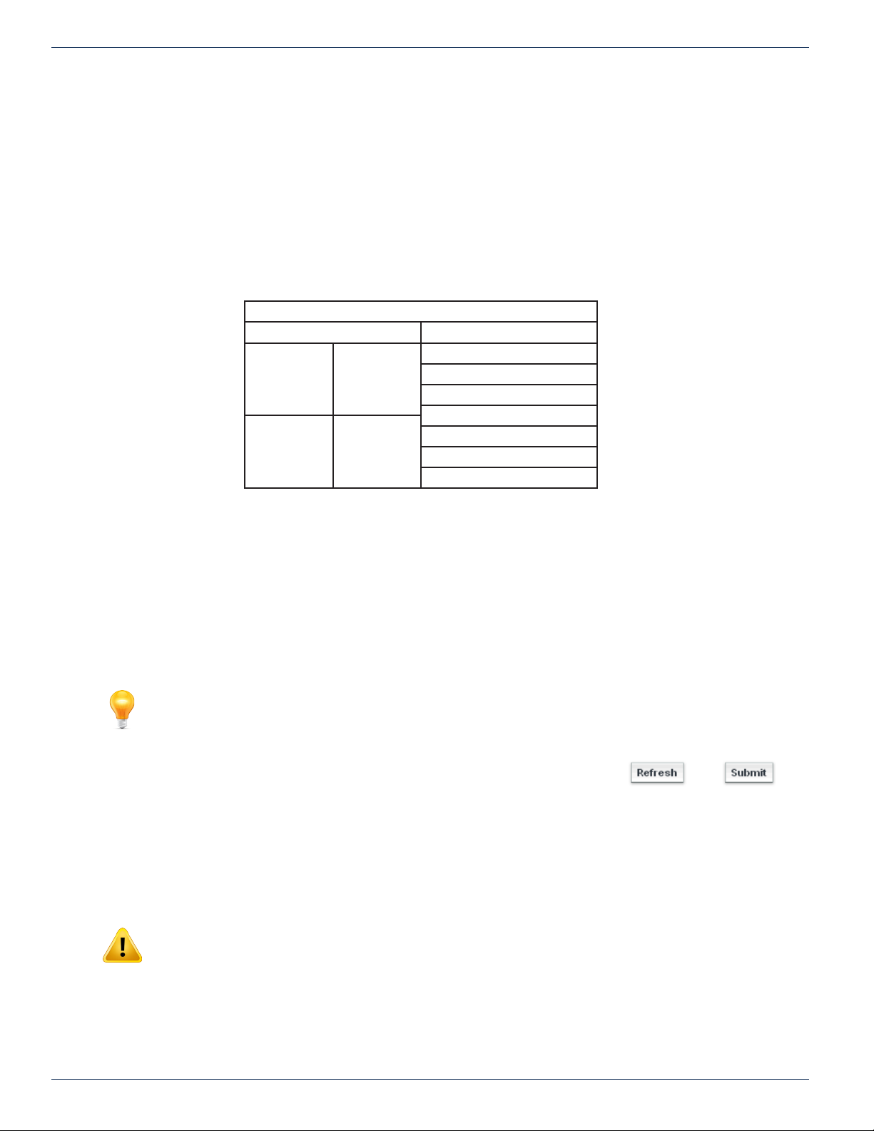
CHAPTER 8: RF OUTPUT TAB
8.1.3 QAM Modulation Type:
The type of QAM modulation is selected here and is dependant mostly on locale. In general, the following applies:
• QAM-B is dened in ITU-T standard J.83 Annex B for use in North America and other territories following same
standard.
• QAM A/C is dened in ITU-T standard J.83 Annex A and J.83 Annex C for general use in Europe, Japan and other
territories following same standard.
8.1.4 Symbol Rate: [2000-7000]
The values presented as preset options depend on the QAM modulation type selected. QAM-B has two predened values, but
QAM-A/C allows a user dened setting along with some common predened values. All DigiVu models support symbol rates
between 2000 and 7000 symbols per second.
Default Values of Symbols/Sec for each QAM Type
5360 ksps 256 QAM User Dened
5056 ksps 64 QAM
QAM-B QAM-A/C
2608 ksps
3478 ksps
4347 ksps
5217 ksps
6086 ksps
6956 ksps
8.1.5 RF Attenuation: [0-26]
The DigiVu internal RF output attenuator may be adjusted to lower the QAM RF output level by up to 26 dB in 1 dB steps. The
output level of the QAM carrier is 57.5 dB +/- 1.5 dB with this attenuator set at 0 dB.
8.1.6 Interleaving:
This setting is only available for the QAM-B mode. The interleaving may be adjusted if required, though it will not normally
require changing from the default value of ‘I/J 128/1’.
• Supported values listed here are dened by the standard:
I/J 64/2, I/J 32/4, I/J 16/8, I/J 8/16, I/J 128/1, I/J 128/2, I/J 128/3, I/J 128/4, I/J 128/5, I/J 128/6, I/J 128/7, I/J 128/8
FYI: The interleaving in QAM-A/C is xed in the standard to 1/J 12/17 and is therefore not listed
in the GUI.
8.2 Platform Control Buttons
8.2.1 Refresh
This control reads the DigiVu stored settings and refreshes the page with the values.
This also will read the encoder card types installed and populate the display with the
discovered types. This is useful when an encoder card type has been changed or a new encoder card installed.
This is not a service affecting operation.
8.2.2 Submit
NOTE: This is a service affecting operation
Figure 8-3: Platform Control Buttons
This control applies all of the changes made on the ‘RF Output’ tab and makes the changes part of the working conguration
of the DigiVu system. If changes have been made click Submit button before navigating away from the page, to avoid all
changes being lost. This attribute may be used to throw away changes made if you change your mind.
8-2 DigiVu® Series Multichannel MPEG-2/H.264 Encoder/Multiplexer with QAM &/or IP Output - Installation & Operation Manual
Page 55
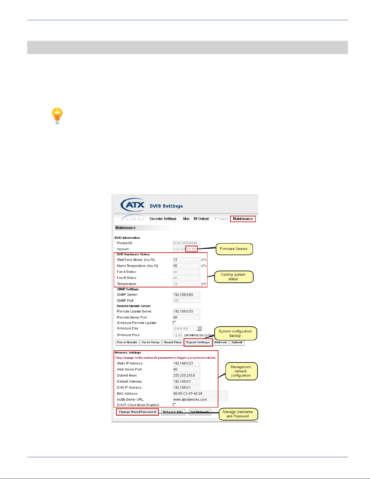
MAINTENANCE TAB
9. Maintenance Tab
From this page, the GUI network conguration settings may be set. Password and Username assess is also changed from
this page.
FYI: In this guide, reference to DigiVu infers DigiVu 3RU, DigiVu CD 3RU and DigiVu Mini 1RU
unless the model is specically stated. Reference to DVIS is synonymous with DigiVu as these
products run on the same rmware.
9.1 Chapter Contents
• “DVIS Information”
• “DVIS Hardware Status”
• “SNMP Settings”
• “Export Settings”
• “Network Settings”
CHAPTER 9: MAINTENANCE TAB
Figure 9-1: Maintenance Tab
DigiVu® Series Multichannel MPEG-2/H.264 Encoder/Multiplexer with QAM &/or IP Output - Installation & Operation Manual 9-1
Page 56
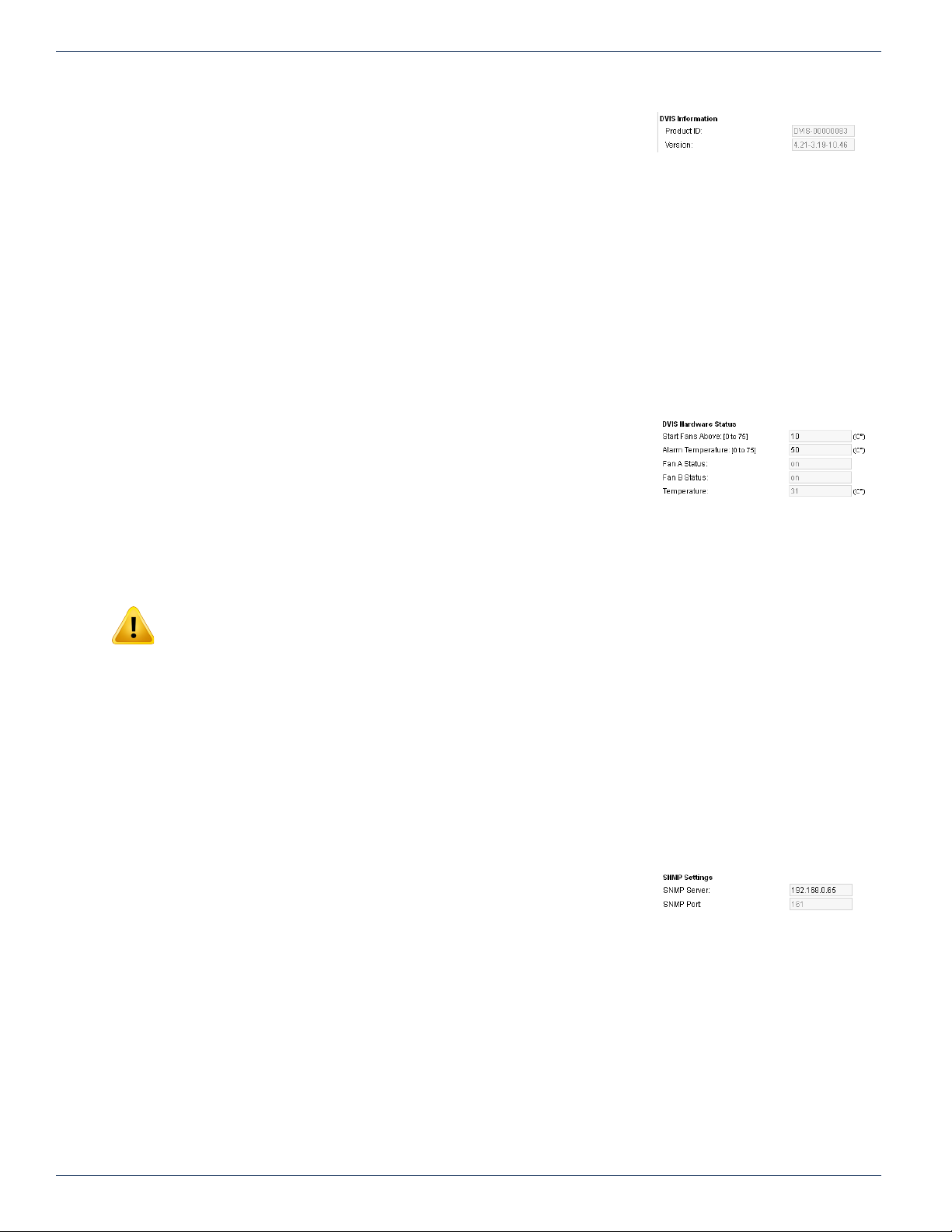
CHAPTER 9: MAINTENANCE TAB
9.2 DVIS Information
9.2.1 Product ID:
This is the hardware serial number.
9.2.2 Version:
The system rmware version installed in the DigiVu. This is the version to check if new rmware is required or recommended.
(Ignore the version number on the top right corner of the GUI display. That number is indicating the version of the GUI, not of
the DigiVu system.) The numbers displayed here directly relate to the rmware version that will be posted to the ATX Networks
support site.
For help with rmware upgrades, see “Contact ATX Networks” on page 15-1 for contact phone numbers.
Information and procedures for obtaining rmware les and installing the rmware may be found at “Firmware Upgrade &
Recovery” on page 12-1
Availability of rmware for your DigiVu may be checked at the ATX Networks support sites listed here “Where to Obtain
Firmware Files” on page 12-3
9.3 DVIS Hardware Status
9.3.1 Start Fans Above: [0 to 75]
Temperature at which the fans begin operating. This may be set manually to any
temperature between 0-75 °C though the default value of 10 °C is recommended.
9.3.2 Alarm Temperature: [0 to 75]
Temperature at which an alarm is initiated. This may be manually set to any temperature between 0-75 °C. This is the
temperature at which an SNMP trap is sent to the SNMP manager, if installed and congured.
Figure 9-2: DVIS Information Section
Figure 9-3: DVIS Hardware Status
NOTE: Setting this temperature articially low is not recommended. When the DigiVu equipment
internal temperature reaches this limit, internal power is switched to a lower power mode and the
unit will remain in this mode to prevent damage to the hardware until the temperature drops below
the set level. This is intended to avert a major hardware failure due to excess heat buildup.
9.3.3 Fan A Status:
Shows whether the fan is On, Off, or Out of Order (indicating fan failure).
9.3.4 Fan B Status:
Shows whether the fan is On, Off, or Out of Order (indicating fan failure).
9.3.5 Temperature:
Current internal temperature of the unit (°C).
9.4 SNMP Settings
All DigiVu support sending SNMP (Simple Network Management Protocol) traps to
a remote SNMP manager. This lets TCP/IP-based network management clients use
a TCP/IP-based internetwork to exchange information about the conguration and
status of nodes. A MIB is required to be compiled into the remote manager in order for
it to understand the SNMP traps.
9.4.1 SNMP MIB
The DigiVu MIB may be browsed with an SNMP Manager once it is compiled into the manager. The following values may be
received by SNMP:
• “RPM measured on Fan 1”
• “RPM measured on Fan 2”
• “Channel 1 Video Status”
• “Channel 2 Video Status”
• “Channel 3 Video Status”
Figure 9-4: SNMP Settings Section
9-2 DigiVu® Series Multichannel MPEG-2/H.264 Encoder/Multiplexer with QAM &/or IP Output - Installation & Operation Manual
Page 57
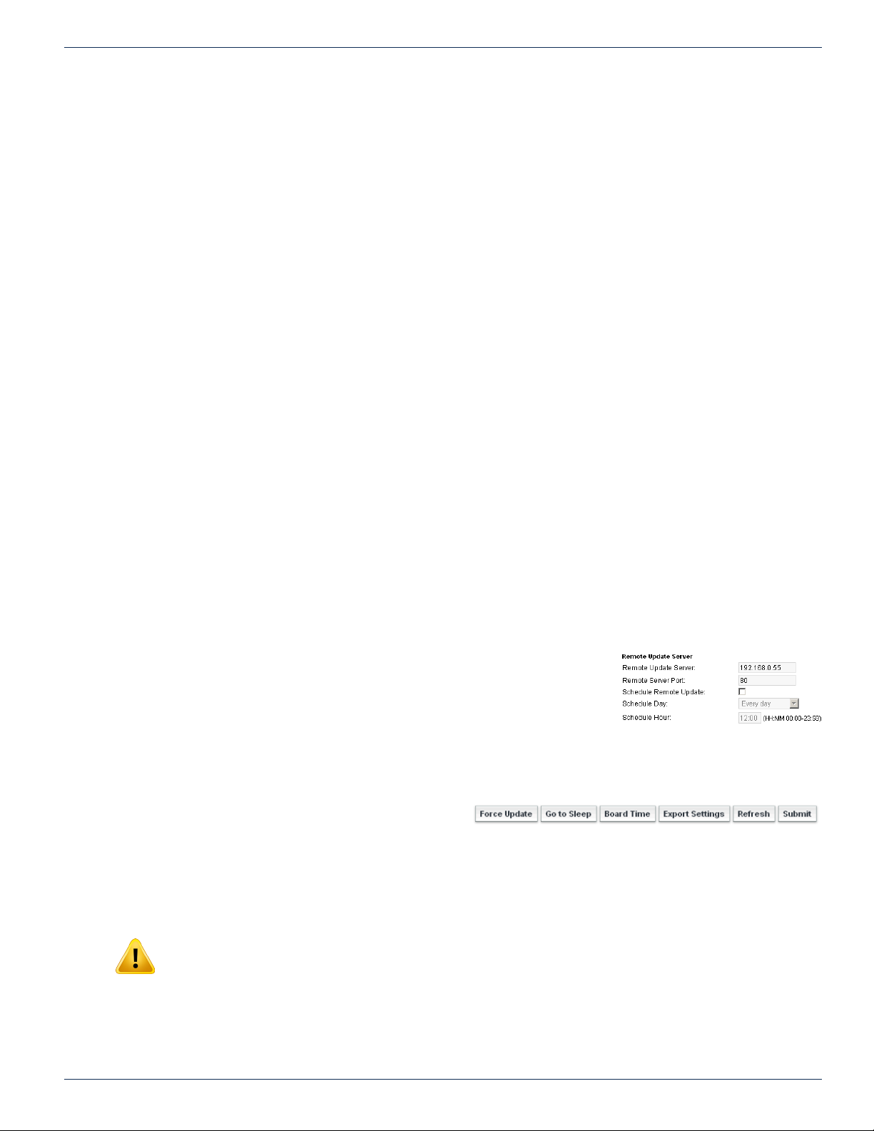
• “Channel 4 Video Status”
• “Channel 5 Video Status”
• “Channel 6 Video Status”
• “Channel 7 Video Status”
• “Channel 8 Video Status”
• “Channel 9 Video Status”
• “Channel 10 Video Status”
9.4.2 Traps Reported by SNMP
• Temperature beyond Threshold (MAJOR)
• Fan Failure (MAJOR)
• Video Status changed channel 1 (MAJOR)
• Video Status changed channel 2 (MAJOR)
• Video Status changed channel 3 (MAJOR)
• Video Status changed channel 4 (MAJOR)
• Video Status changed channel 5 (MAJOR)
• Video Status changed channel 6 (MAJOR)
• Video Status changed channel 7 (MAJOR)
• Video Status changed channel 8 (MAJOR)
• Video Status changed channel 9 (MAJOR)
• Video Status changed channel 10 (MAJOR)
SNMP Server:
This is the IP address of the remote Management Console which is the computer that will receive traps sent by the DigiVu and
is the computer with SNMP software installed. This is the system which will receive the SNMP traps. Only one SNMP manager
may be specied.
CHAPTER 9: MAINTENANCE TAB
9.4.3 SNMP Port:
By default, the DigiVu assigns port 161 for sending and receiving requests. This is the default and commonly used port for
SNMP messaging. SNMP uses UDP (User Datagram Protocol).
9.4.4 SNMP MIB
If you want to implement SNMP monitoring you will need the SNMP MIB. Get this by requesting it from ATX Networks technical
support at the numbers listed in “Contact ATX Networks” on page 15-1.
9.5 Remote Update Server:
Feature not currently implemented.
Remote Server Port: Feature not currently implemented.
Schedule Remote Update: Feature not currently implemented.
Schedule Day: Feature not currently implemented.
Schedule Hour: Feature not currently implemented.
9.6 Platform Control Buttons
9.6.1 Force Update
Feature not currently implemented.
9.6.2 Go to Sleep
This control causes the DigiVu to go into a low power mode which reduces the internal temperature buildup.
Figure 9-5: Remote Update Server
Figure 9-6: Maintenance Control Buttons
NOTE: This is a service affecting operation.
9.6.3 Board Time
This control allows the real time clock to be set so that time stamps on the logs reect real time. This only needs to be set once
as the backup battery installed in the DigiVu equipment will keep the clock running during any power outages. The battery may
DigiVu® Series Multichannel MPEG-2/H.264 Encoder/Multiplexer with QAM &/or IP Output - Installation & Operation Manual 9-3
Page 58
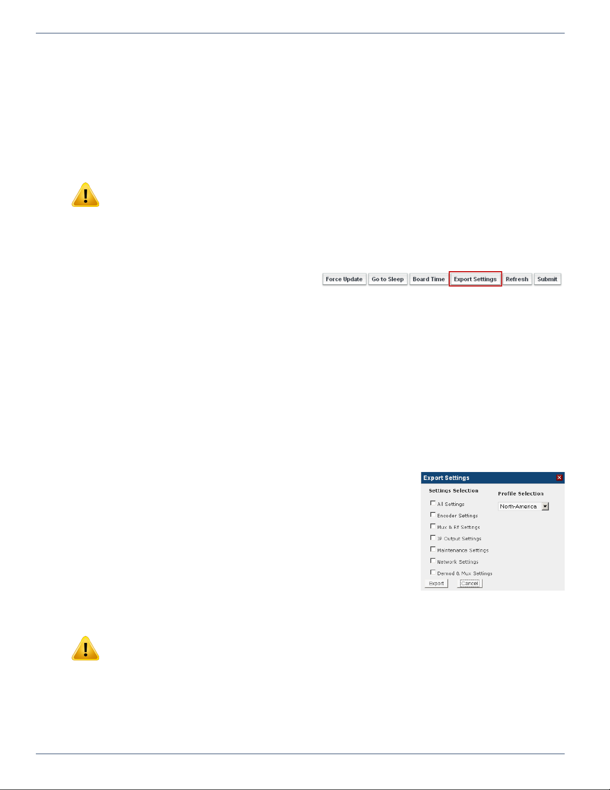
CHAPTER 9: MAINTENANCE TAB
need to be changed from time to time, see “13.1 Field Replacement of Realtime Clock Battery” on page 13-1.
9.6.4 Refresh
This control reads the DigiVu’s stored settings and refreshes the page with the values. This also will read the encoder card
types installed and populate the display with the discovered types. This is useful when an encoder card type has been
changed or a new encoder card installed.
This is not a service affecting operation.
9.6.5 Submit
NOTE: This is a service affecting operation
This control applies all of the changes made on the ‘Maintenance’ tab (except for ‘Network Settings’ which are applied
separately) and makes the changes part of the working conguration of the DigiVu system. If changes have been made click
Submit button before navigating away from the page, to avoid all changes being lost. This attribute may be used to throw
away changes made if you change your mind.
9.6.6 Export Settings
This control allows the operator to export the programmed
conguration as a le. The exported le may be used for
backup and archive purposes or to allow fast and easy
deployment of multiple DigiVu with similar conguration.
The le may be imported to any number of units requiring similar settings, thus saving the time to manually program each unit
before deployment. The process of exporting the conguration le is shown in Figure 9-9.
Figure 9-7: Export Settings Button
9.6.7 Import Settings
Importing a settings le is done with the same upload utility used for upgrading rmware. For information on importing a
settings le, see “12.6 Firmware Upgrade Process” on page 12-3.
9.6.8 Import/Export Firmware Versions Must Match
Because different rmware versions might contain different features and therefore different elds for setting parameters,
export and upload will only work reliably and correctly if the originating and receiving DigiVu are running the same rmware
version. It is obvious that there will be problems if originating and receiving device don’t have same feature set and it will not
be known by the device how to congure settings.
9.6.9 Settings Selection
The DigiVu platform provides several choices for the granularity of the amount of data
to be saved when settings are exported. To start the settings export process, click
the Export Settings button. When the export settings dialog is opened, see Figure
9-8, a number of choices are provided to allow just the required data to be exported.
One may be tempted to just select ‘All Settings’ as this may intuitively seem the best
choice but carefully consider the circumstances of the machine receiving the data. If
it intended to use the data as a backup which will be restored to the same DigiVu in
the same network, this is the best choice. If the receiving DigiVu is another machine in
another location, the choice of data exported must be made with careful consideration.
An explanation of the data that will be exported with each selection is outlined here:
1. All Settings
All settings of the entire DigiVu platform. Perfect for a backup database.
WARNING:—If a remote re-conguration of a DigiVu (the target DigiVu) is performed while
connected through an IP network, the ‘All Settings’ check box has to be unchecked. Otherwise, the
exported ‘Network Settings’ of the source DigiVu (the source of the exported le) will load into the
target DigiVu and those settings will be incorrect unless the target and the source DigiVu are the
same machine. Every remotely accessible device has unique ‘Network Settings’ which will be
overwritten if we check this box. The result will be that internet access to the remote DigiVu is lost
and someone has to visit it locally to reset the Network Settings appropriately for network access.
Figure 9-8: Settings Selection
2. Encoder Settings
9-4 DigiVu® Series Multichannel MPEG-2/H.264 Encoder/Multiplexer with QAM &/or IP Output - Installation & Operation Manual
Page 59
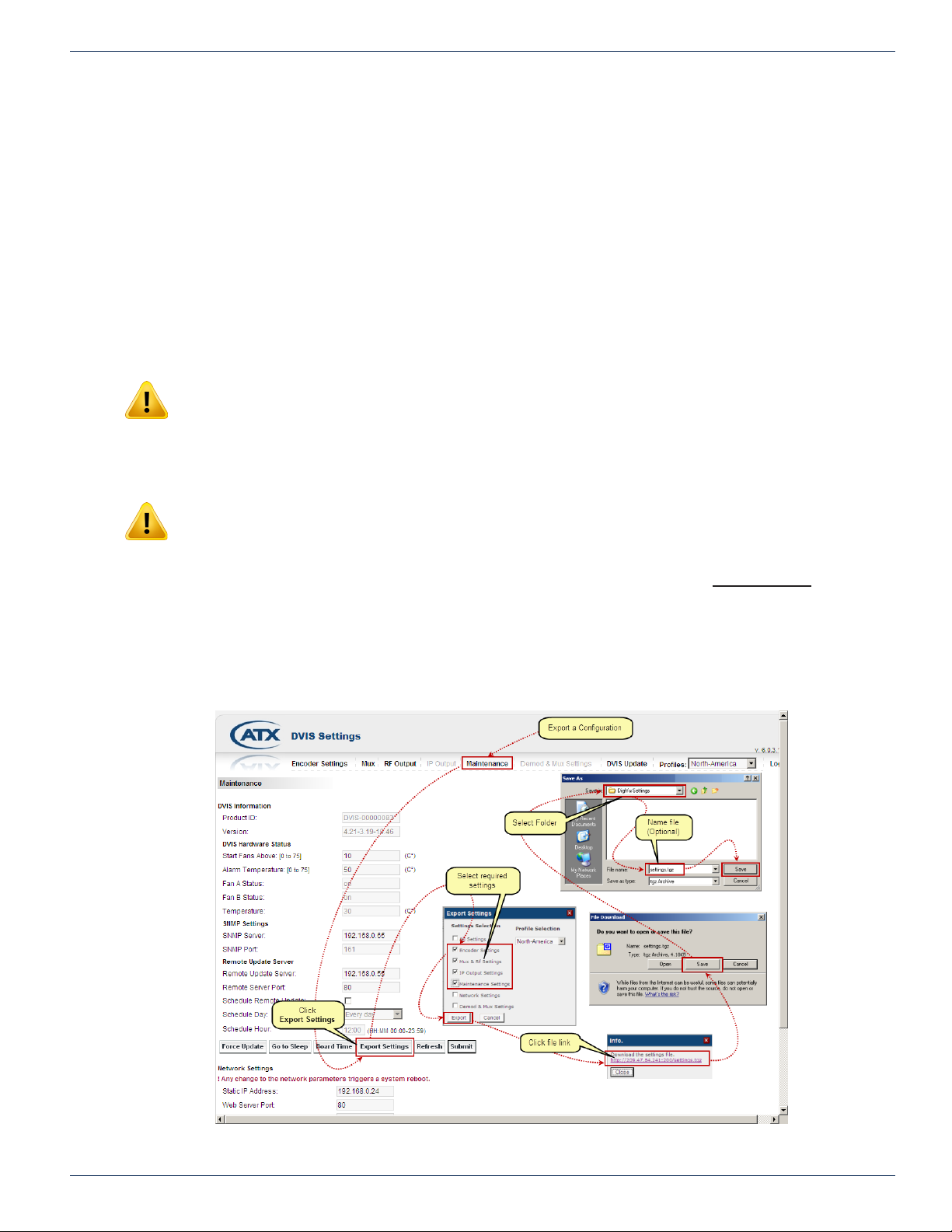
CHAPTER 9: MAINTENANCE TAB
All settings from ‘Encoder Settings’ page get exported and later loaded in the other DigiVu.
3. MUX and RF Settings
All settings from ‘MUX and RF Output’ pages get exported and later loaded in the other DigiVu.
4. IP Output Settings
All settings from ‘IP Output’ page get exported and later loaded in the other DigiVu.
5. Maintenance Settings
All settings from ‘Maintenance’ page other than Network settings get exported and later loaded in the other DigiVu.
6. Network Settings
All settings from ‘Network Settings’ section on the Maintenance page get exported and later loaded in the other
DigiVu.
7. Demod and MUX Settings
All settings from the ‘Demod and MUX Settings’ page get exported and later loaded in other DigiVu.
NOTE: Because the ‘Demod and MUX Settings’ page uses data from an incoming QAM in a
specic QAM RF distribution network, exporting and loading these parameters only makes sense
if the ‘receiving’ DigiVu operates in the exact same QAM RF network. Otherwise in a different QAM
RF network this export settings le won’t work because the QAM channels, programs, frequencies,
etc. could be different, therefore incorrect values will be loaded.
NOTE: In order to generate settings in the ‘Demod & MUX Settings’ page it is required to connect
the DigiVu to the QAM RF network to collect data as required for the Demod & MUX page.
Parameters in all other GUI pages are generated directly in DigiVu, but parameters in the Demod
& MUX Settings page are a combination of real-life received/analyzed data and modication
performed by the DigiVu. It is important to note that the Demod & MUX page data always and only
can be created in the system in question and cannot be generated in a lab/ofce located elsewhere.
9.6.10 Quick Guide to Export Settings
The screen capture construction in Figure 9-9 may be used to clarify these instructions.
1. Click the Maintenance tab
Figure 9-9: Export Settings Procedure Illustrated
DigiVu® Series Multichannel MPEG-2/H.264 Encoder/Multiplexer with QAM &/or IP Output - Installation & Operation Manual 9-5
Page 60
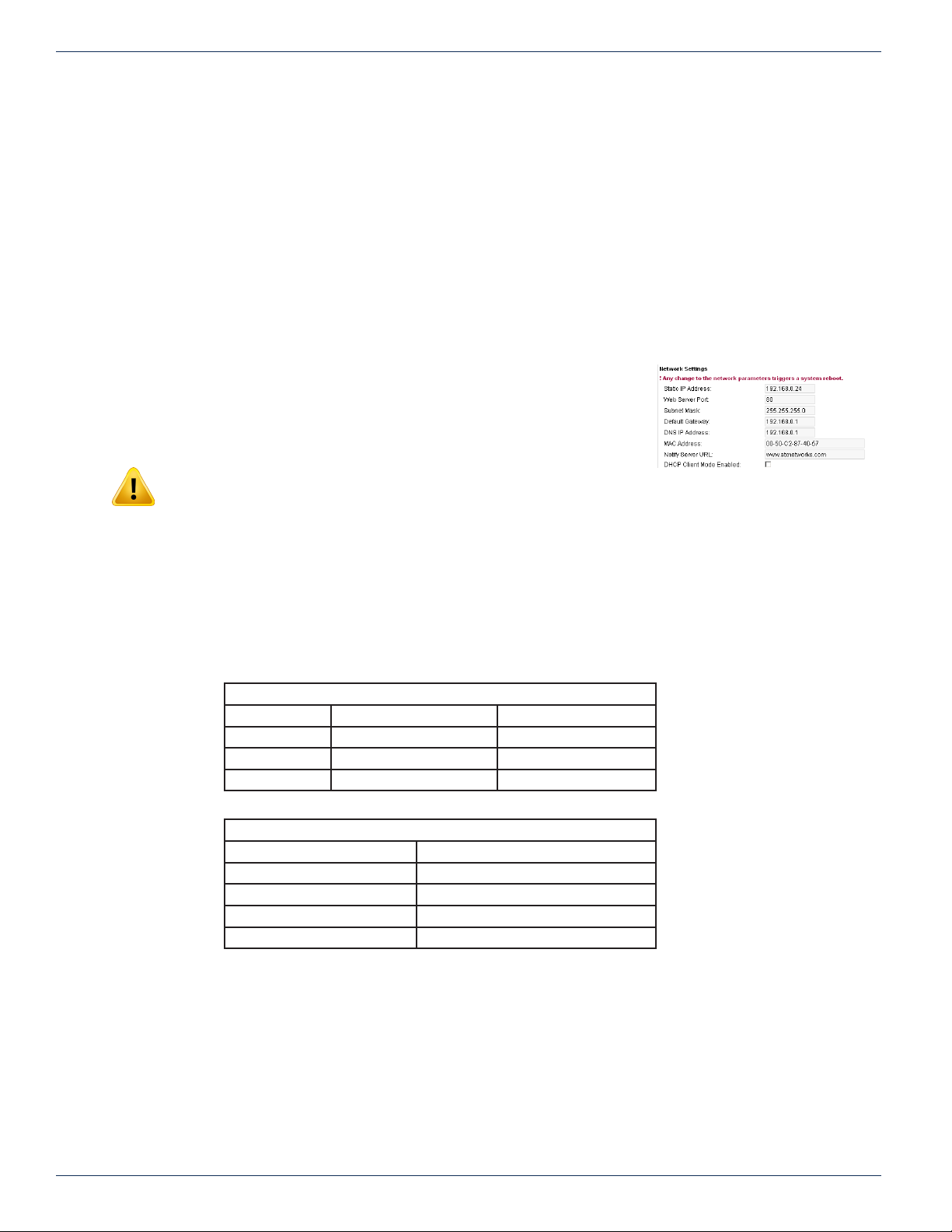
CHAPTER 9: MAINTENANCE TAB
2. Click Export Settings button.
3. A window opens allowing the selection of the dataset to be exported from this DigiVu. After selection click Export.
4. A new window will open with a web-link to download the settings le.
5. Click this hyper-link.
6. Another new window opens with a prompt to act on the le, (it’s format depends on the browser used and it’s version)
asking to open or save this le.
7. Save this le in a known location on the PC. You may accept the offered le name or change it in any way you want
to personalize it to identify the DigiVu it is saved from. Without renaming, every DigiVu export le will be named
identically.
8. This le can be used later to be uploaded into a DigiVu through the DVIS Update page, in same way as new rmware
would be loaded. The execution of such uploaded le happens in same way as when rmware les get uploaded, and
after that process is done the receiving DigiVu will have same parameter settings as originating DigiVu.
9.7 Network Settings
This section denes the setting for the Ethernet GUI port on the DigiVu 1RU Mini front
panel and the DigiVu 3RU back panel. The conguration of the Gigabit Ethernet card
is detailed in “IP Output Tab” on page 11-1.
NOTE: Any change to network parameters triggers a reboot when
applying the changes with the ‘Set Network’ button.
9.7.1 Static IP Address:
An IP (Internet Protocol) address is a numerical identication assigned to devices participating in a computer network utilizing
the Internet Protocol for communication between nodes. When a computer is congured with a Static IP address it always
uses the same IP address. When a computer is congured with Dynamic IP addressing it automatically procures an IP address
from a DHCP server when required. If the installation requires a static IP address that value would be entered here. This value
is greyed out when DHCP Client Mode is enabled. The greyed out address is not the address procured from the DHCP server.
The DHCP assigned address shows up if the button ‘Network Info.’, see Figure 9-13. The address range that is supported as
well as the default IP address settings are outlined in the following tables:
IP Address 192.168.0.23
Subnet Mask 255.255.255.0
Web Server Port 80
Gateway 192.168.0.1
DNS IP Address Not Dened
Figure 9-10: Network Settings Section
IP Address Range Supported
IP Class Start Address End Address
A 10.0.0.0 127.255.255.255
B 128.0.0.0 191.255.255.255
C 192.0.0.0 223.255.255.255
Factory Default IP Addresses
9.7.2 Web Server Port:
This is the TCP/IP port that is used to remotely access the DigiVu. The default value is port 80 which is the well known port
for HTTP protocol web servers and is the default value used by a web browser if no port is specied. For additional security or
to allow the product to work properly behind some rewall congurations, the port used for access may need to be changed.
If the port is changed to 8000, for example, the product would then be accessed by a web browser with the following address
notation: http://xxx.xxx.xxx.xxx:8000 where the actual public IP address replaces the x’s
9.7.3 Subnet Mask:
A subnet mask must be set to dene what part of the network address is applicable to the subnet that the DigiVu exists on.
This should be set according to the overall network design. The default value of 255.255.255.0 will work ne with the default
9-6 DigiVu® Series Multichannel MPEG-2/H.264 Encoder/Multiplexer with QAM &/or IP Output - Installation & Operation Manual
Page 61
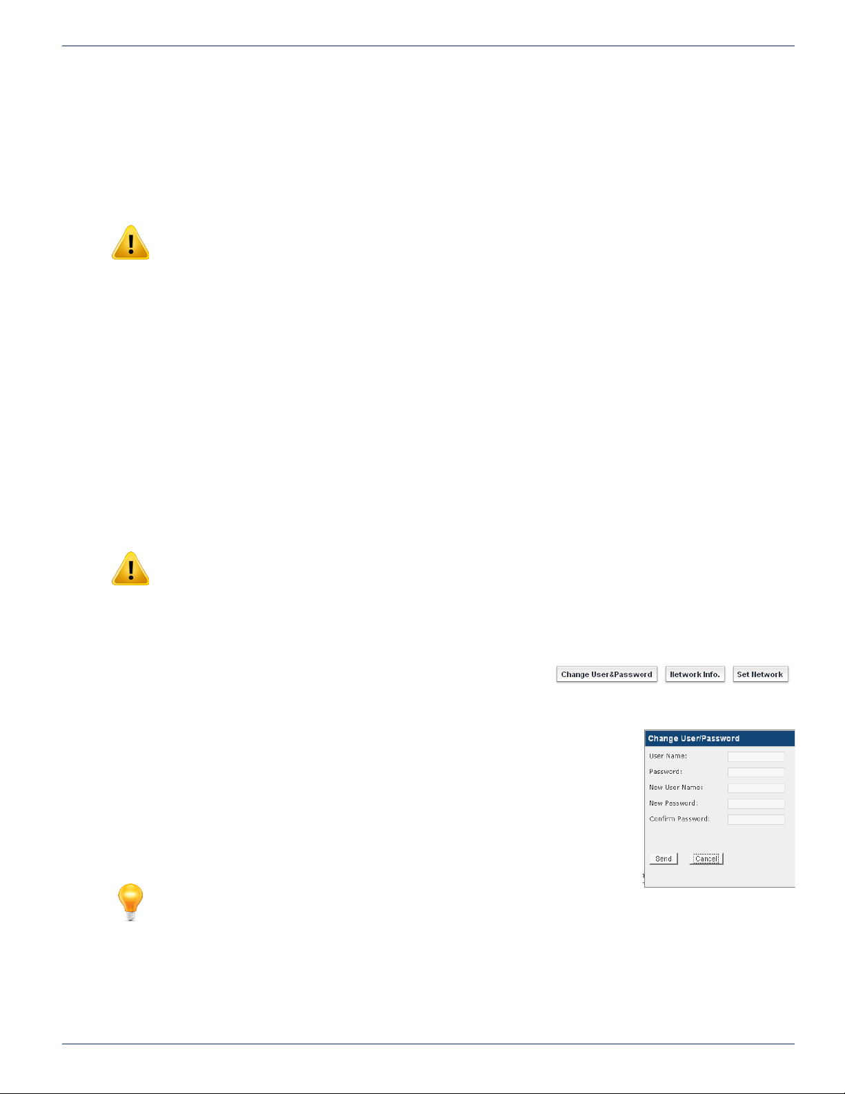
private network address of 192.168.0.23
9.7.4 Default Gateway:
This is the address of a router that the product is connected to and is installed between the unit and access to the internet or
intranet. If there is no router or internet access this value is irrelevant.
9.7.5 DNS IP Address:
NOTE: Cannot be ignored for remote access! This address must be entered, though it may be
any IP address including an address that is not specically a DNS server. A Google DNS Address
that may be used is 8.8.8.8
DNS (Domain Name System) servers translate human-readable domain names into machine-readable IP addresses and the
reverse. For remote access a DNS IP address must be entered.
9.7.6 MAC Address:
A MAC (Media Access Control) address is a unique identier assigned to network adapters or network interface cards (NICs)
by the manufacturer to uniquely identify them on a LAN. It is used to identify the DigiVu on the network to a DHCP server and
to other computers. It is hard coded into the DigiVu at the factory and cannot be changed. For example, the MAC address is
used by a cable modem to acquire an IP address in DHCP mode.
9.7.7 Notify Server URL:
This feature is not yet implemented
CHAPTER 9: MAINTENANCE TAB
9.7.8 DHCP Client Mode Enabled:
DHCP (Dynamic Host Conguration Protocol) automates assigning an IP address to the management access port. DHCP is
commonly used with cable modems so likely DHCP Client Mode will need to be enabled if a cable modem will be connected
to the management port for remotely accessing the DigiVu.
NOTE: Once DHCP is enabled and an IP address is assigned you will need to externally
determine what the IP address was set to in order to access the DigiVu again through the Ethernet
port. Further, you may need to set your computer to the corresponding subnet if you are directly
connected to the DigiVu on the network. Your Network Administrator may be able to help with this.
For information on setting the IP address of the PC see “5.4 Connecting to the GUI” on page 5-2.
9.8 Platform Network Control Buttons
9.8.1 Change Username & Password
For security purposes, the DigiVu has a Username and Password which must
be entered for access to the GUI. The username and passwords may be changed through the
dialog that opens with this control. After changing the username and/or password, the DigiVu
must be rebooted in order for the changes to become effective. After the reboot, the new
username and password must be used. The username and password may not be set to null
(No entry or blank).The DigiVu system provides for a single system user and password who is
allowed to modify all settings. The dialogue that opens when you click Change User&Password
button allows the user name and password to be modied. After changing the settings, click
Send to apply the new settings. The DigiVu GUI will close and you will be requested to log in
under the new credentials.
Figure 9-11: Platform Network Control Buttons
FYI: If the Username or Password have been changed and subsequently
forgotten, there is a way to recover the DigiVu without loss of programmed
conguration. A username/password reset le is available which can workaround
this problem. Contact ATX Networks technical support at the numbers listed
under ”Contact ATX Networks” on page 15-1 for assistance.
DigiVu® Series Multichannel MPEG-2/H.264 Encoder/Multiplexer with QAM &/or IP Output - Installation & Operation Manual 9-7
Figure 9-12: Change
Username and Password
Page 62
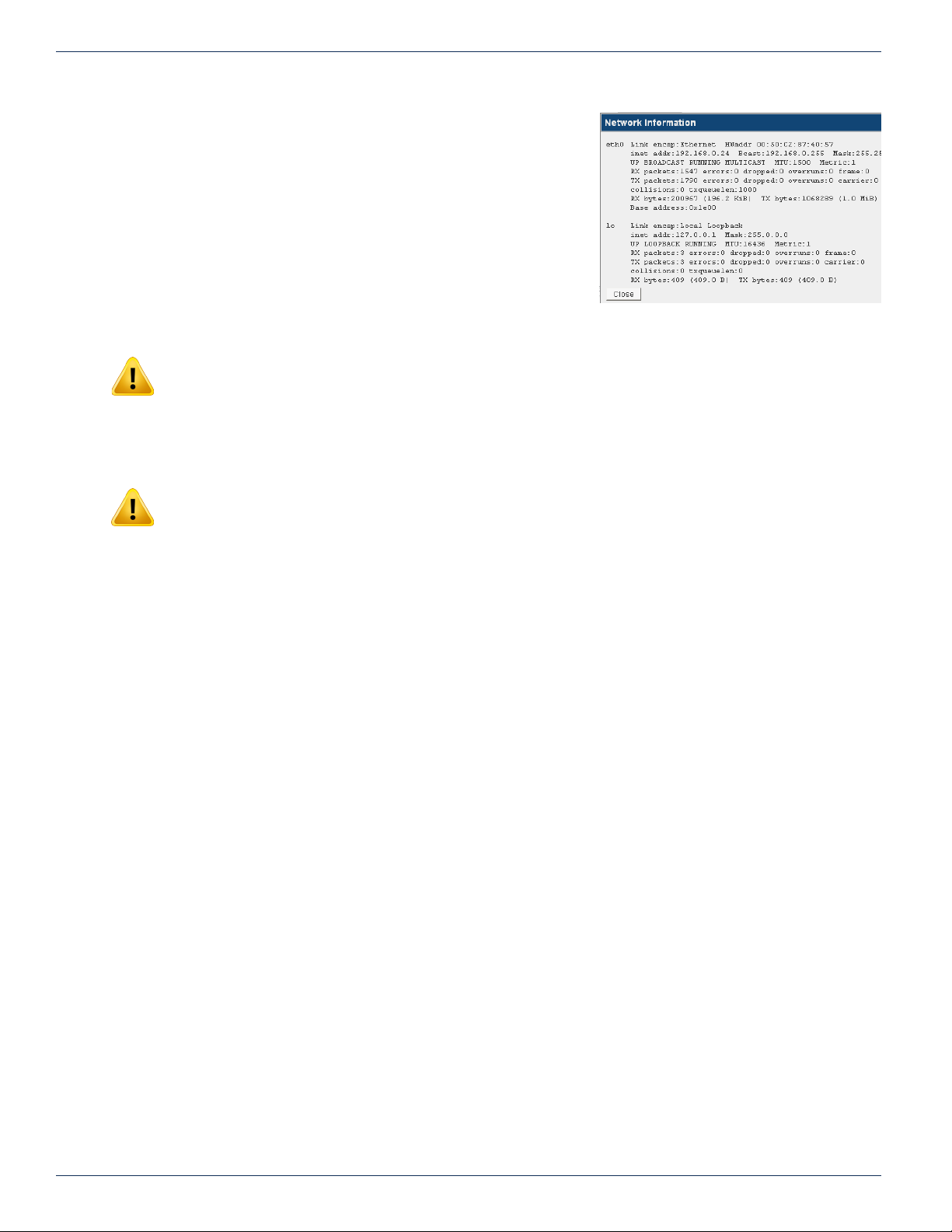
CHAPTER 9: MAINTENANCE TAB
9.8.2 Network Info
This button opens an information window that summarizes Ethernet network
information such as IP address (even DHCP assigned), packets received
and transmitted, the link status, data collisions and the number of RX and
TX bytes. This is for information only. An example is shown in Figure 9-13.
9.8.3 Set Network
NOTE: For every pressing of the ‘Set Network’ button, the platform will reboot.
If any parameter in the ‘Network Settings’ section has been changed, they need to be saved and applied to the DigiVu in order
to take effect. This is done by clicking the Set Network button which applies the network conguration changes. A platform
reboot will always take place.
Figure 9-13: Network Information Window
NOTE: If the network address has been changed, then the platform will reboot and you will need
to open a new browser session with the new address entered in Internet Explorer. This is exactly
the process described earlier in Chapter “5. The GUI” on page 5-1. For specic details see “5.6.4
Static IP Address Assignment” on page 5-6.
9-8 DigiVu® Series Multichannel MPEG-2/H.264 Encoder/Multiplexer with QAM &/or IP Output - Installation & Operation Manual
Page 63
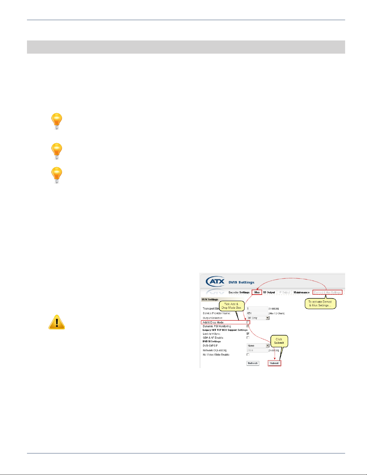
DEMOD & MUX TAB
10. Demod & Mux Settings Tab
In this chapter we detail the controls which are used to operate the Demodulator and Multiplexer to achieve the results that
are required in an Add/Drop application. For Add/Drop applications, all add/drop settings are discussed along with limits and
some suggestions as to what values are most applicable.
FYI: In this guide, reference to DigiVu infers DigiVu 3RU, DigiVu CD 3RU and DigiVu Mini 1RU
unless the model is specically stated. Reference to DVIS is synonymous with DigiVu as these
products run on the same rmware.
FYI: The ‘Demod and Mux’ tab will be activated only if a demod card is installed. If there is no
demod installed, this tab will be greyed out in the GUI.
FYI: The DigiVu platform can only accommodate one DEMOD card.
CHAPTER 10: DEMOD & MUX SETTINGS TAB
10.1 Chapter Contents
• “Quick Guide to Demod & Mux Conguration”
• “Demod & Mux Settings”
• “Demodulator Settings”
• “Demodulator Settings Buttons”
• “Add & Drop Settings”
• “Add & Drop Settings Buttons”
• “PID Display Tree”
10.2 Quick Guide to Demod & Mux Conguration
10.2.1 Activate the Demod & Mux Settings Tab
If the ‘Demod & Mux Settings’ tab is greyed out it will need
to be activated on the ‘Mux’ tab. Open the Mux tab and tick
the ‘Add & Drop Mode’ box, then click Submit button, see
Figure 10-1.
NOTE: Clicking ‘Submit’ is a service affecting
operation.
Figure 10-1: Activate Add/Drop Mode on the Mux Tab
DigiVu® Series Multichannel MPEG-2/H.264 Encoder/Multiplexer with QAM &/or IP Output - Installation & Operation Manual 10-1
Page 64
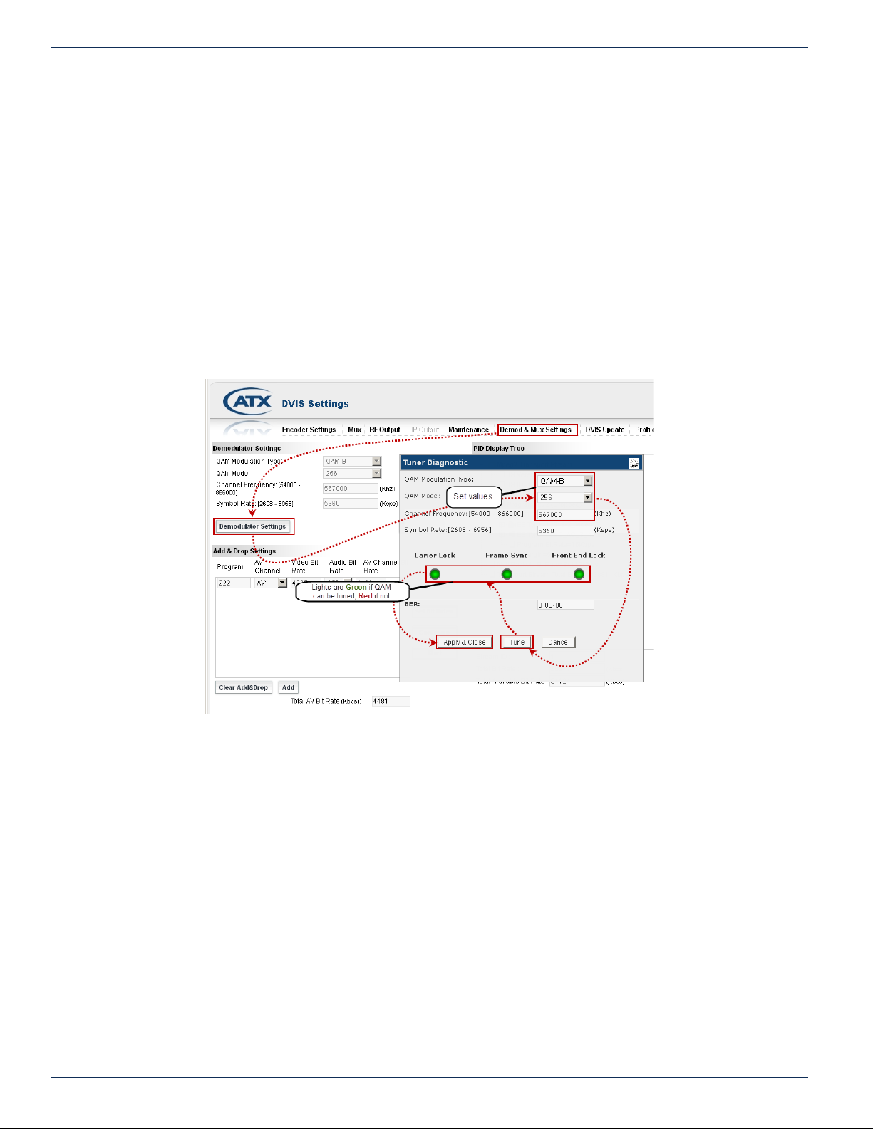
CHAPTER 10: DEMOD & MUX SETTINGS TAB
10.2.2 Quick Guide to Tuning the Demodulator
Refer to Figure 10-2 for clarication of this process.
1. Open the ‘Demod & Mux Settings’ tab.
2. Depending on the QAM Demodulator type (Qam -B ATSC vs QAM A/C, ETSI), the symbol rate may need to be set
rst. For QAM-B the setting is automatic, for QAM A/C obtain the symbol rate from the cable system operator.
3. Click Demodulator Settings button.
4. Set QAM type, QAM Mode and Channel Center Frequency. These values will be copied into ‘Demod Settings’ when
tuning is nished.
5. Click the Tune button. The tuning process will take some time. If the QAM can be tuned, the indicators, which are
initially red, will turn green. The tuner is also determining signal quality during this time.
6. When lights have turned green and ‘BER’ (Bit Error Rate) value is populated (allow some time for BER data collection),
click the Apply & Close button.
7. Click the Analyze button. The analyze info window opens for about 1 minute then displays ‘Completed’.
8. The PID Display Tree is populated with the detected streams and their MPEG properties.
Figure 10-2: Tune the Demodulator
10-2 DigiVu® Series Multichannel MPEG-2/H.264 Encoder/Multiplexer with QAM &/or IP Output - Installation & Operation Manual
Page 65
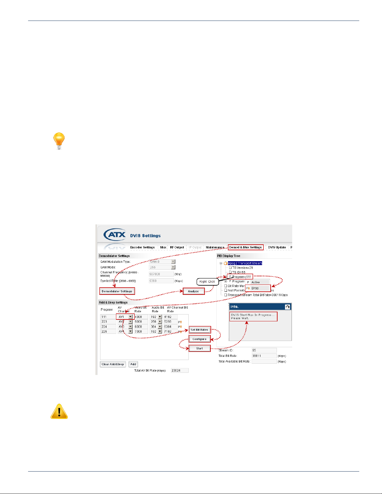
10.2.3 Quick Guide to Drop and Add a Program
Refer to Figure 10-3 for clarication of this procedure.
1. Left click the program to be dropped in the ‘PID Display Tree’ in order to highlight it
2. Right click that program and a drop down menu appears (Active, Drop).
3. Click Drop. A replacement program is populated in the Add & Drop Settings window area with same program number
as the dropped program, The dropped program is greyed out.
4. In the ‘Add & Drop Settings’ section select the ‘AV Channel’ (the DigiVu encoder port that is physically connected to
local baseband source) to be inserted; AV1 or AV2 etc. (Initially the drop downs for ‘AV Channel’ will show ‘None’).
5. Click Set Bit Rates. DigiVu will analyze the incoming stream and attempt to assign the highest bit rate to each added
AV Channel that the available space will allow.
FYI: The bitrate computed in step 5 will be assigned to each program in ‘AV Channel Bit Rate’
column. Since the algorithm is assigning all available bitrate headroom, it might happen that these
values are extremely high and need adjustment downward. To do so, click into the eld with
assigned ‘Video Bit Rate’ and enter an appropriate bitrate number (this number depends on several
factor). Do this for all available ‘AV Channels’.
6. The assigned bitrate for each encoder may be adjusted downward if necessary.
7. Select “Audio Bit Rate” for every available AV Channel. The recommended setting is 192 kbps.
8. Click Congure button. The settings are saved to the DigiVu conguration.
9. Click Start button. This starts the multiplexer add/drop process.
CHAPTER 10: DEMOD & MUX SETTINGS TAB
Figure 10-3: Add or Drop a Program
NOTE: Clicking ‘Start’ is a service affecting operation
DigiVu® Series Multichannel MPEG-2/H.264 Encoder/Multiplexer with QAM &/or IP Output - Installation & Operation Manual 10-3
Page 66
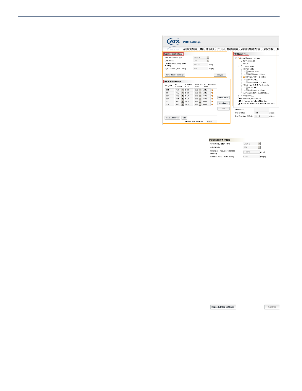
CHAPTER 10: DEMOD & MUX SETTINGS TAB
10.3 Demod & Mux Settings
The following is a description of the ‘Demod & Mux Settings‘
conguration page. The page is divided into 3 main sections
as shown in Figure 10-4:
• Demodulator Settings
• Add & Drop Settings
• PID Display Tree
Each of these screen sections are described next.
10.4 Demodulator Settings
This area displays the parameters of the QAM demodulator. These values are
adjustable in the ‘Tuner Diagnostic’ dialog that opens when you click the Demodulator
Settings button. That will be discussed below. The four parameters that are displayed
are:
Figure 10-4: Demod and Mux Settings Conguration Page
Figure 10-5: Demodulator Settings
10.4.1 QAM Modulation Type:
This is the type of QAM standard that the Demod will use and is determined mostly by locale and the Demod Card installed
(two versions are available); generally QAM B for North America and QAM A/C for Europe (and appropriate territories following
standards from North America/Europe/Japan).
10.4.2 QAM Mode:
Depending on the QAM Type selected above, the QAM mode is preset to a few possible values. For QAM-B available options
are 64 QAM and 256 QAM. For QAM-A/C available options are 16QAM, 32QAM, 64QAM, 128QAM and 256QAM.
10.4.3 Channel Frequency: [54000 - 866000]
This is the center frequency of the EIA/RF/CCIR channel to be demodulated. The possible values are 47000 kHz to 897000
kHz. Do not enter any commas or other punctuation marks.
10.4.4 Symbol Rate: [2608 - 6956]
The symbol rate of the QAM channel. For QAM-B for selected QAM mode there is only one valid symbol rate which is
automatically entered. For QAM-A/C, several possible symbol rates are preset and there is a possibility to enter a user dened
number as well.
10.4.5 BER:
This is the measured Bit Error Rate (or Bit Error Ratio) on the tuned QAM channel. This value should be very low, preferably
0.0E-08, indicating a quality signal. If the BER is worse than 1.0E-06 an investigation into transmission problems on the cable
system should be undertaken.
10.5 Demodulator Settings Buttons
10.5.1 Demodulator Settings
This control opens the Tuner Diagnostics window that permits changing the relevant
conguration and verifying the successful tuning of the specied QAM. The screen
capture construction in “Quick Guide to Tuning the Demodulator” on page 10-2 outlines the process. The window contains
three indicators which are red by default when the window opens. Opening the Tuner Diagnostics window will always initially
display the three indicators as red, even when the tuner is currently properly tuned and locked. This screen must be refreshed
every time it is opened by clicking the Tune button. If the QAM demodulator cannot tune and lock on the carrier, the indicator
lights remain red, however, upon successful tuning and locking of sync, all three of the lights should be green and in a few
moments the BER (Bit Error rate) is measured and populated. The action of clicking the Tune button is not service affecting
Figure 10-6: Demodulator Settings
Buttons
10-4 DigiVu® Series Multichannel MPEG-2/H.264 Encoder/Multiplexer with QAM &/or IP Output - Installation & Operation Manual
Page 67
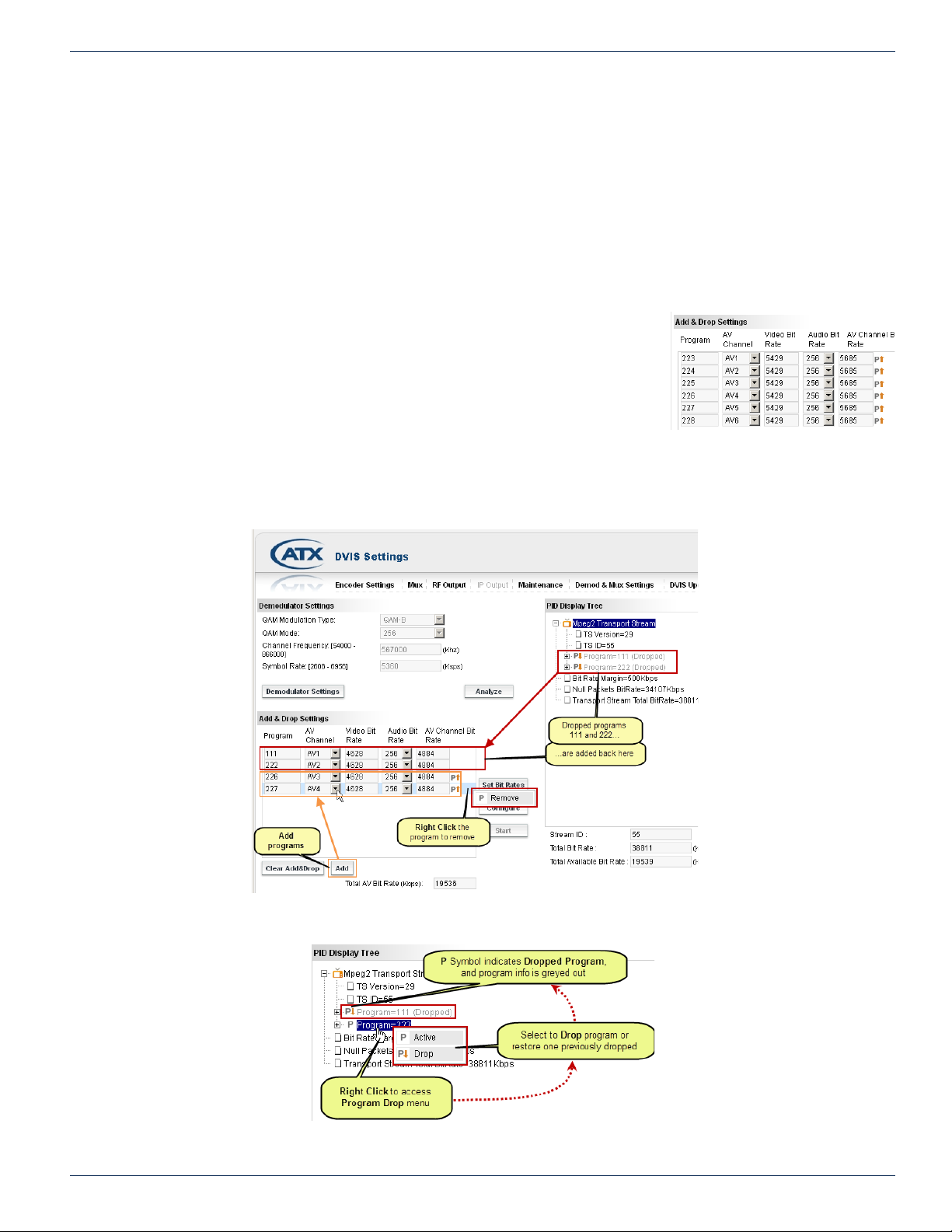
unless the QAM parameters have been changed since the window was opened.
10.5.2 Tune - Control
After entering or selecting the values in the dialog, click the Tune control. This causes the tuner to attempt to nd the carrier
detect frame sync and lock on the frequency. Successful tuning results in the three indicators lighting green and the tuner then
attempts to evaluate the bit error rate of the channel. The BER is posted in a few moments if successful.
10.5.3 Apply and Close
When the lights are all green and the BER is posted, click Apply & Close to apply and save the settings and close the window.
The 4 set parameters will be copied into the “Demodulator Setting” section.
10.6 Add & Drop Settings
This section displays the local encoder settings in the ‘Add & Drop’ mode only. This
is where local encoder video and audio encoding bit rates and program numbers are
set when the add/drop mode is activated. If the Add/Drop mode is not being used,
encoder parameters are set on the ‘Encoder Settings’ page. In Add/Drop mode,
some parameters can still be set in ‘Encoder Settings’ page, but the ones which
are restricted are greyed out. Programs will automatically be added in this window
when an incoming program is dropped in the ‘PID Display Tree’. Other local encoder
channels may be added into an incoming QAM (if enough bitrate is available) from this
window as required without dropping every program from incoming QAM. Conguring
local programs will force the use of the automatic bit rate congurator, the ‘Set Bit Rates’ button, but the bit rate assigned to
CHAPTER 10: DEMOD & MUX SETTINGS TAB
Figure 10-7: Add & Drop Settings
Section
Figure 10-8: Adding and Dropping Programs
Figure 10-9: Drop or Restore a Program
DigiVu® Series Multichannel MPEG-2/H.264 Encoder/Multiplexer with QAM &/or IP Output - Installation & Operation Manual 10-5
Page 68
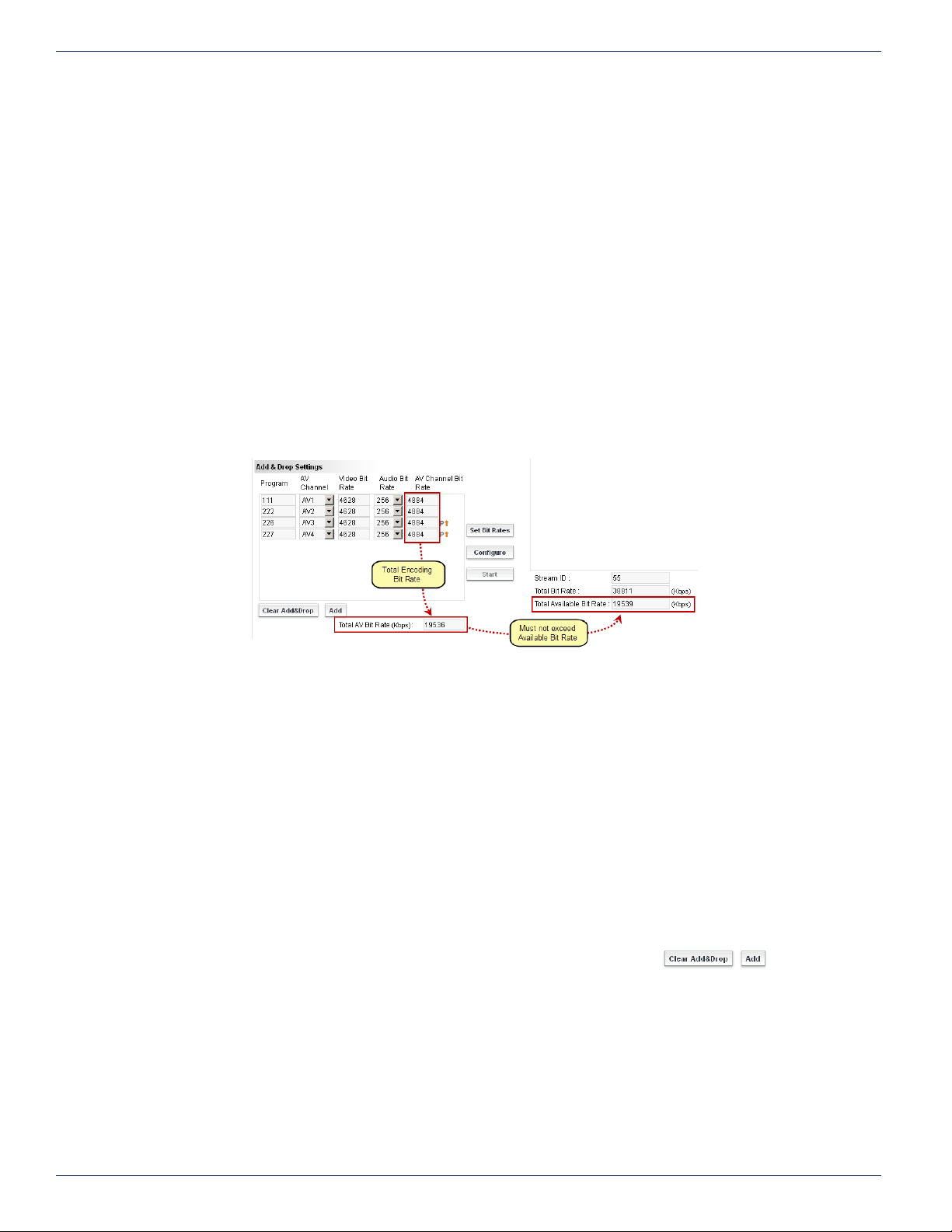
CHAPTER 10: DEMOD & MUX SETTINGS TAB
an encoder could exceed the output capability of the used encoder card (for example for SD it’s 8000 kbps). If this happens,
change the bit rate manually to a lower value. This can happen because the algorithm assigns all available bitrate in a QAM,
and if the QAM is ‘empty’ the available bitrate is high.
10.6.1 Program
This is the MPEG program number assigned to the program. This may be changed to any number as required by your system.
If a program is being dropped, the program number assigned to the inserted program is the number of the dropped program.
The program number assigned here will show up in ‘Encoder Settings’ page as greyed out numbers (in appropriate port view).
10.6.2 AV Channel
This is the number of the local encoder port. On the ‘Encoder Settings’ page,in the ‘Ports View’ section, this same encoder is
referred to as a ‘Port Number’. See “6.5.1 Port Numbering Convention” on page 6-3 for the port numbering. By default this
value is set to ‘None’ which represents the program being dropped from the incoming QAM without replacement
10.6.3 Video Bit Rate
The bit rate assigned to the local encoder after clicking the Set Bit Rates button. This value depends on the installed encoder
card. If the bit rate congurator automatically assigns a bit rate that exceeds max allowed bitrate, manually set it to less.
A higher bit rate equates to higher quality video transmission but setting a high bit rate will not improve low quality video
presented to the encoder input.
10.6.4 Audio Bit Rate
This is the bit rate of the audio program. Depending on the encoder card installed, default values will be available to be chosen
as required by your system. Recommended setting is 192 kbps.
10.6.5 AV Channel Bit Rate
This is the aggregate bit rate for the overall program including the individual encoded video and the audio streams.
10.6.6 Total AV Bit Rate (kbps)
This is the aggregate total bit rate of all of the programs added in the ‘Add & Drop Settings’ section. The total includes the video
and the audio encoder bit rates. This value may equal but must not exceed the value of ‘Total Available Bit Rate’ displayed
below the ‘PID Display Tree’ section.
10.7 Add & Drop Settings Buttons
A description of the functionality of the control buttons of the ‘Add & Drop Settings’
feature.
10.7.1 Clear Add & Drop Button
If there are any programs entered into the program list, this button clears all entries. The added programs may also be
removed one at a time by right clicking the programs and select Remove when prompted. For programs that are dropped from
the ‘PID Tree’, they may be added once again only from the ‘PID Tree’ section.
10.7.2 Add Button
This enters new programs in the list that have no relationship with the incoming QAM; i.e. are not replacements for dropped
Figure 10-10: Observe MUX Bitrate
Figure 10-11: Add & Drop Settings
Buttons
10-6 DigiVu® Series Multichannel MPEG-2/H.264 Encoder/Multiplexer with QAM &/or IP Output - Installation & Operation Manual
Page 69

incoming programs, just newly added programs to the QAM. Programs are entered with default audio bit rates which may be
changed. The video bit rate will be calculated so do not enter the desired video bit rate until after clicking the Set Bit Rate
button.
10.7.3 Set Bit Rates Button
This control automatically calculates the video bit rate of each added program based
on the bandwidth available. This is determined by measuring the transport stream
null stufng, if any, and the bit rate made available by any dropped programs. It then
subtracts the audio bit rates that were specied by the added programs plus some
stream headroom, and divides the remainder by the number of added programs. The
result is automatically entered as the ‘Video Bit Rate’. Each individual video bit rate
may be changed at this point but do not allow the aggregate bit rate to exceed the
‘Total Available Bit Rate’ specied in the display under the ‘PID Display Tree’. This is not service affecting.
10.7.4 Congure Button
This control saves the specied settings for the added programs to the DigiVu multiplexer. This is not service affecting.
10.7.5 Start - Control
This reads the settings saved with the ‘Congure’ control and applies the settings to the multiplexer.
NOTE: Clicking ‘Start’ is a service affecting operation
CHAPTER 10: DEMOD & MUX SETTINGS TAB
Figure 10-12: Set Bit Rates Buttons
10.8 PID Display Tree
The ‘PID Display Tree’ is an MPEG stream analyzer display of the incoming programs
detected in the received QAM transport stream PAT and PMT tables. See Figure 10-9
for an example of the PID tree display. Only programs listed in the transport stream
tables will be displayed. This display makes selecting and dropping the correct program
easier. Clicking on the + signs opens the stream parameters for closer inspection of
individual PIDs and detected bit rates. Bit rates are read over a short period of time
and are a snap shot of the stream and are valid only at the time of analysis; if they
subsequently change the display is not updated.
Figure 10-13: TS Components in PID Display Tree
10 . 8.1 MPEG-2 Transport Stream Components
The MPEG-2 Transport Stream displayed in the PID Display Tree is the QAM transport stream as demodulated by the demod
card. It comprises the following components described next.
Figure 10-14: PID Display Tree
Section
10.8.2 TS Version:
Each time the stream analyzer function is used, this number increments. It does not relate to anything about the stream itself.
10.8.3 TS ID:
This is the ID number assigned to the transport stream at it origin. This would be assigned to the stream multiplex before being
modulated to the source QAM channel.
DigiVu® Series Multichannel MPEG-2/H.264 Encoder/Multiplexer with QAM &/or IP Output - Installation & Operation Manual 10-7
Page 70
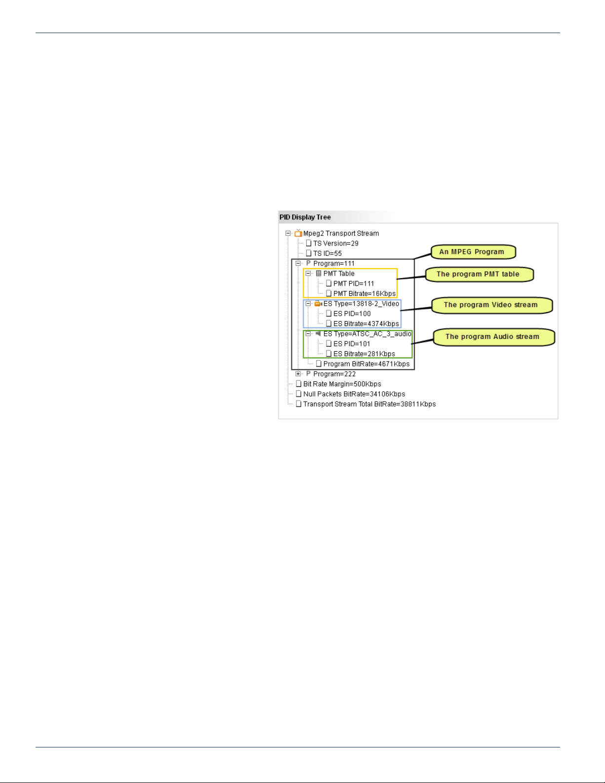
CHAPTER 10: DEMOD & MUX SETTINGS TAB
10.8.4 Bit Rate Margin
This is the margin or headroom detected in the incoming stream. This allows some small change in the aggregate bit rate of
all of the TS programs without exceeding the QAM channel maximum bit rate.
10.8.5 Null Packets Bit Rate
The transport stream may not contain all MPEG stream data. If the analyzer detects null stufng, it displays the data rate of
the nulls here.
10.8.6 Transport Stream Total Bitrate
This is the bit rate of the QAM channel. In the case illustrated above, a QAM-B 256 QAM channel with a data rate of 38811
kbps.
10.8.7 Program Components
Each program listed in the stream PAT and PMT
tables will be displayed along with their assigned
MPEG program number. Each program is further
broken down into it’s components:
10.8.8 PMT Table
The table that announces the PID assigned to
each individual elementary stream; the Audio and
Video streams. The PMT table is contained within
it’s own data stream with a PID assigned
• PMT PID
The PID assigned to the PMT table.
This cannot be changed.
• PMT Bit rate
The bit rate of the PMT table. Information
only.
10.8.9 ES Type=13818-2 Video
The stream analyzer will determine the video
stream type and display it here. In this example
the stream is detected as 13818-2 Video. The
number 13818-2 is the standard that denes MPEG-2 video. If your system carries different video, this will reect the video
detected. ES means Elementary Stream. Each program stream is comprised of one or more elementary streams.
• ES PID
The PID assigned to the Video Elementary Stream.
• ES Bit Rate
The bit rate of the Video Elementary Stream in kbps. In the illustrations, the actual bit rate displayed is the total of the
payload data rate specied by the standard plus header packets
10.8.10 ES Type=ATSC_AC_3 Audio
The stream analyzer will determine the audio stream type and display it here. In the example illustrated the stream is detected
as AC-3 Audio. If your system carries different audio, such as MPEG-1, the analyzer will reect the audio stream type detected.
ES means Elementary Stream. Each program is comprised of one or more elementary streams.
• ES PID
The PID assigned to the Audio Elementary Stream.
• ES Bit Rate
The bit rate of the Audio Elementary Stream in kbps. In the illustrations, the actual bit rate displayed is the total of the
payload data rate specied by the standard plus header packets.
Figure 10-15: Showing Program Components in PID Display Tree
10-8 DigiVu® Series Multichannel MPEG-2/H.264 Encoder/Multiplexer with QAM &/or IP Output - Installation & Operation Manual
Page 71
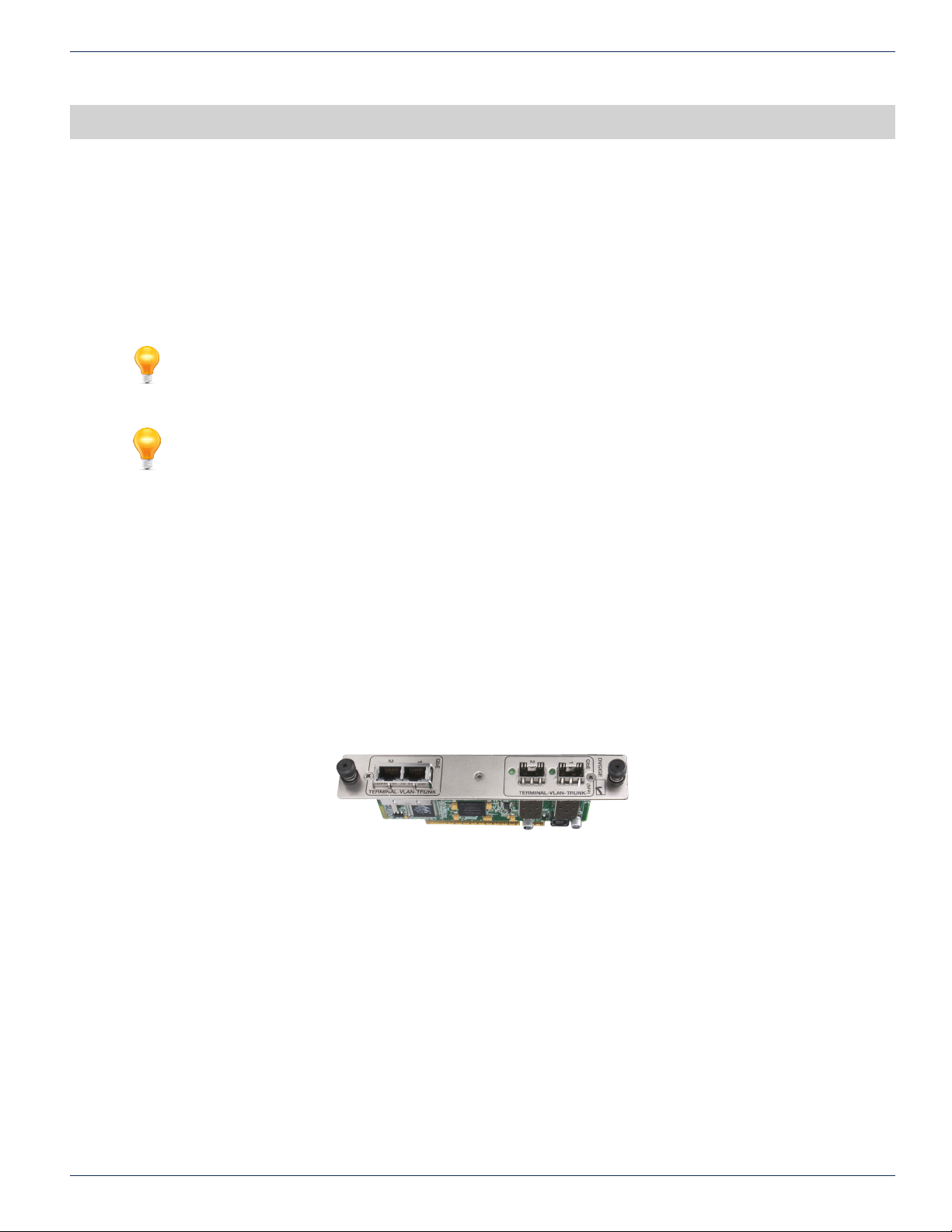
IP OUTPUT TAB
11. IP Output Tab
This chapter is about the conguration of the Gigabit Ethernet (GbE) card shown in Figure 11-1. The GbE option supports
transmission by multicast or unicast of the multiplex created by the encoders. The DigiVu platform can simultaneously create
a QAM and IP output with programming duplicated on both. In this case the IP output will be a single multiplex of the created
programs, an MPTS. If the DigiVu is congured for IP output only, then SPTS multiplexes may be created for each program.
In IP output only mode the user can select either SPTS or MPTS transmission, but not a mixture of both. See “11.13 Stream
Settings” on page 11-8 to activate the SPTS feature.
FYI: Activation of the ‘IP Output’ tab requires that an IP Card be installed. If there is one installed
check in the “Encoder Settings Tab” on page 6-1 to see that the IP Card is detected. The ‘IP
Output’ tab must also be activated on the ‘Mux’ tab. See “Mux Tab” on page 7-1.
FYI: In this guide, reference to DigiVu infers DigiVu 3RU, DigiVu CD 3RU and DigiVu Mini 1RU
unless the model is specically stated. Reference to DVIS is synonymous with DigiVu as these
products run on the same rmware.
CHAPTER 11: IP OUTPUT TAB
11.1 Chapter Contents
• “Enabling the IP Output Tab”
• “Support for VLAN Tagging”
• “Gigabit Ethernet Card Fundamentals”
• “Quick Guide to the Gigabit Ethernet Card”
• “IP Output Conguration”
• “VLANS Settings”
• “GbE Port Numbering”
• “Two VLANs Automatically Created”
• “Stream Settings”
Figure 11-1: GbE Output Module
DigiVu® Series Multichannel MPEG-2/H.264 Encoder/Multiplexer with QAM &/or IP Output - Installation & Operation Manual 11-1
Page 72
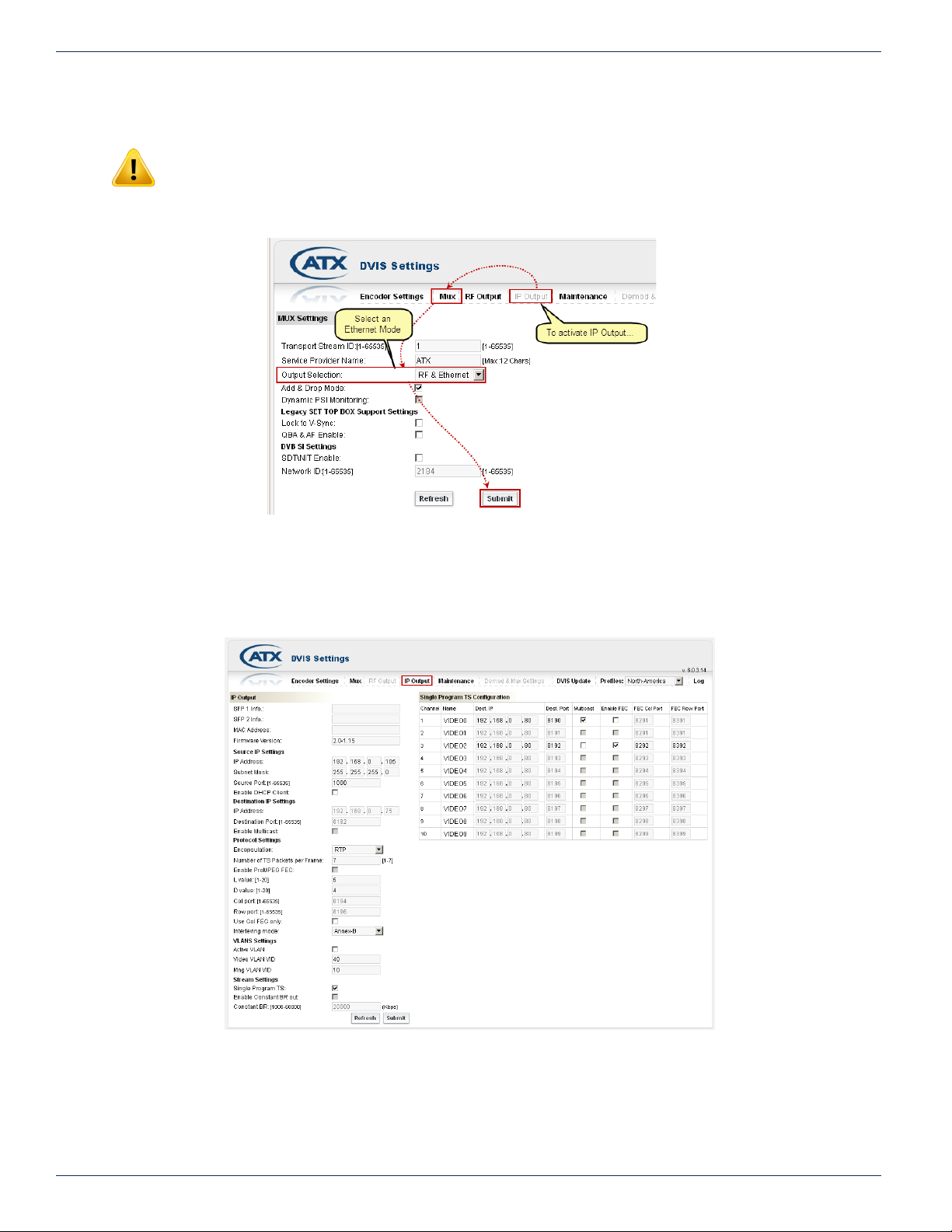
CHAPTER 11: IP OUTPUT TAB
11.2 Enabling the IP Output Tab
NOTE: The Ethernet card is supported in slots 2(DigiVu Mini) and 5(DigiVu and DigiVu CD) only.
If the GbE card has just been inserted and the GUI IP Output tab is greyed out, the Ethernet functionality must rst be
Figure 11-2: Activate the IP Output Tab
activated. That is done on the ‘Mux’ tab; see “Mux Settings” on page 12-1. The procedure is shown in Figure 11-2. The DigiVu
can produce Ethernet only or RF only outputs or both simultaneously; features that are also activated on the ‘Mux’ tab.
Figure 11-3: IP Output Tab
11-2 DigiVu® Series Multichannel MPEG-2/H.264 Encoder/Multiplexer with QAM &/or IP Output - Installation & Operation Manual
Page 73

11.3 Support for VLAN Tagging
The Ethernet card supports the automatic creation of two VLANs or Virtual Local Area Networks. This feature may be used to
allow both routing the streaming of the output video and access to the GUI on two separate virtual networks as if there were
two separately wired physical networks installed. In VLAN tagging, the broadcast domain is extended across the VLAN as if
the devices in the group were all locally connected together. VLANs also extend the DHCP server requests across the same
virtual network if DHCP is used to assign network addresses. In this way the GUI and streaming IP output may be assigned
addresses independently from two separate pools or DHCP servers.
Without the use of VLANs, the GUI port may be connected to any of the GbE ports since the four GbE ports are congured as
an IP switch, and any other GbE port may be connected to a local switch or access network such as a cable modem. In this
manner a single path to the central headend may be used to carry both management and streaming video. The disadvantage
of this method is that at the central headend consolidation switch, and depending on the type of switch, the streams may all
appear on the destination device port such that a management computer may have streaming video from many DigiVu devices
routed to it and conversely, the video receiving device may experience undesired management trafc.
By using VLANs, the video and management access streams, while arriving together, are separated at the destination switch
into two distinct VLAN groups, each routed to a specic physical port dened by the VLAN. In this way all streaming video will
be routed to the video receiving device, like a CherryPicker and the management access will be routed to the management
computer(s). In this way only trafc intended for a receiving device will receive it. Since broadcast domains are extended over
VLANs, all of the features of a broadcast domain are extended across the VLAN as well. See “VLANS Settings” on page 11-6
for specic details on this.
CHAPTER 11: IP OUTPUT TAB
11.4 Gigabit Ethernet Card Fundamentals
11.4.1 SFP Support
The card supports two SFP modules (Small Form-Factor Pluggable) allowing single mode and multi-mode optical modules to
interface to the GbE ports providing long range and secure interfaces to switches, routers and remote sites. Many types and
manufacturers of SFP have been tested with good results but because of the vast offering of various SFP modules, it is not
possible to test all of them. It remains up to the customer to verify that his SFP will work as expected.
11.4.2 Integrated Switch
The Gigabit Ethernet card integrates a GbE switch on board allowing the card to transmit simultaneously from up to 4 Ethernet
ports; 2 copper RJ45 type ports and 2 SFP ports. SFP Modules must be purchased separately and so far, SFP modules that
are incompatible have not been identied.
11.4.3 Protocol Support
The card supports DHCP, ICMP and ARP protocols as well as VLAN tagging. Before unicast transmission is started the
card will rst attempt to nd the destination MAC address of the receiving side (when using unicast transmission) using ARP
protocol. When the MAC address is found, transmission begins.
11.5 Quick Guide to the Gigabit Ethernet Card
If more information is required, see the detailed conguration descriptions following this quick guide.
1. Insert the Gigabit Ethernet card into slot 2 (DigiVu Mini) or 5 (DigiVu and DigiVu CD).
2. Open the ‘Mux’ tab and change the ‘Output Selection’ to either ‘Ethernet Only’ or to ‘RF & Ethernet’.
3. Verify insertion and detection of the card on the ‘Encoder Settings’ tab – Card is detected as ‘ETH1000’.
4. Open the IP Output tab and congure the Gigabit Ethernet Card with the following parameters as required:
• Source IP Settings:
◦ IP Address – The IP address of the Ethernet Card physical interface. Only one required for all 4 ports.
◦ Subnet Mask – Identies the subnet of the IP address specied above.
◦ Source Port – Source port that will be specied when sending the TS data.
◦ Enable DHCP Client – When selected, the Gigabit Ethernet Card will obtain a dynamic IP address
(Source address) from a DHCP server and use this address for all Ethernet transmissions. A source
port is not obtained from a DHCP server.
• Destination IP Settings:
◦ IP Address – The IP address that the Gigabit Ethernet Card transmits to.
◦ Destination Port – The virtual destination port that is used for the TS data transmission.
DigiVu® Series Multichannel MPEG-2/H.264 Encoder/Multiplexer with QAM &/or IP Output - Installation & Operation Manual 11-3
Page 74

CHAPTER 11: IP OUTPUT TAB
◦ Enable Multicast – When selected, the Gigabit Ethernet Card will not attempt to nd the destination IP
address with ARP before transmission begins.
• Protocol Settings:
◦ Encapsulation – The encapsulation type that is used for the TS data transmission.
◦ Number of TS Packets Per Frame – how many TS packets will be used in each Ethernet frame.
◦ Enable Pro-MPEG FEC – enables the Pro MPEG forward error correction.
◦ L Value, D Value – FEC Parameters.
◦ Col Port – port number to use for transmission of FEC column data.
◦ Row Port – port number to use for transmission of FEC row data.
◦ Use Col FEC Only – use only Column FEC for the FEC.
◦ Interleaving Mode – which interleaving mode to use for the FEC.
5. Click the Submit button.
11.6 IP Output Conguration
11.6.1 SFP 1 Info.
This is where the GUI will report if there is an SFP installed in SFP Slot 1. If there is
no SFP it will say “Not Connected”.
11.6.2 SFP 2 Info.
This is where the GUI will report if there is an SFP installed in SFP Slot 2. If there is no SFP it will say “Not Connected”.
11.6.3 MAC Address:
A MAC (Media Access Control) address is a unique identier assigned to network adapters or network interface cards (NICs)
by the manufacturer to uniquely identify them on a LAN. It is used to identify the GbE Card on the network to a DHCP server
and to other computers. It is hard coded into the GbE Card at the factory and cannot be changed. This is the Mac Address for
all four output ports, collectively, of the Gigabit Ethernet Card. If DHCP is used, this is the address to use for a reservation in
the DHCP server for the video output device.
11.6.4 Firmware Version:
The rmware version installed on the Gigabit Ethernet card - for information only.
11.7 Source IP Settings
This section sets the physical IP address conguration for the SFP and Electrical
Ethernet ports. All ports are replicated in an integrated switch, so there is only one IP
address assigned to all of the physical ports collectively.
11.7.1 IP Address:
A static IP address may be specied here that is assigned to the Ethernet ports, collectively. Only one address may be
assigned and this will be the source address that is reported in the resulting unicast or multicast streams.
Figure 11-4: IP Output Conguration
Figure 11-5: Source IP Settings Section
11.7.2 Subnet Mask:
If a static IP address is assigned, enter the subnet mask for the entered network address.
11.7.3 Source Port: [1-65535]
This is the source port number that may be assigned to the Ethernet ports, collectively. Only one port may be assigned and
this will be the Source Port that is reported in the resulting unicast or multicast streams.
11.7.4 Enable DHCP Client:
The Ethernet card supports DHCP Client Mode on the Gigabit ports separately from the unit’s management port. This option
enables the DHCP client on the Gigabit Card Ethernet ports only. Only a single address will be requested from the DHCP
server. The source port will still need to be assigned even if DHCP client is enabled since DHCP will not assign a port number.
When DHCP client is enabled, the IP address that is reported in the greyed out IP address and subnet settings above do not
reect the actual IP address obtained. If that information is required, the DHCP server should be consulted, looking for the
address that was assigned to the MAC address shown above.
11-4 DigiVu® Series Multichannel MPEG-2/H.264 Encoder/Multiplexer with QAM &/or IP Output - Installation & Operation Manual
Page 75
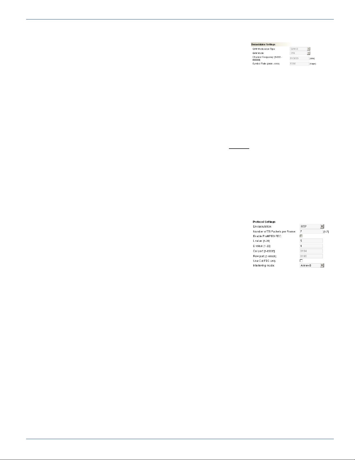
11.8 Destination IP Settings
This section sets the IP address that is assigned to the outgoing IP stream when
working in MPTS mode. There will be only one multiplex created and only one address
may be assigned. This address will be used across all of the output Ethernet ports as
the four ports are on an integrated switch.
11. 8.1 IP Address:
This is the IP address that is assigned to the output unicast or multicast MPTS stream and will be reported in the resulting
MPTS stream as the Destination IP Address.
11. 8 . 2 Destination Port: [1-65535]
This is the port number that is assigned to the output unicast or multicast MPTS stream and will be reported in the resulting
MPTS stream as the Destination Port Number.
11.8.3 Enable Multicast:
This check box enables the use of multicast as an output. The Ethernet card does not use the actual assigned destination
IP address range to determine if unicast or multicast transmission is desired. In other words, merely assigning a multicast
address in the range 224.0.0.0 through 239.255.255.255 will not cause the output to be multicast.
• If this check box is unticked
ARP protocol will be used to nd and establish a unicast connection to the computer or receiving device with
the destination IP address. The stream will be unicast to the destination address specied. If the address of the
destination specied is not found, the transmission will default to multicast.
• If this box is ticked
The Ethernet interface will not need to nd the destination IP address before beginning transmission. It will assume
that there are multiple receivers of the stream. The stream will be multicast to the address specied.
CHAPTER 11: IP OUTPUT TAB
Figure 11-6: Destination IP Settings
11.9 Protocol Settings
In this section, some conguration settings for the IP protocol may be changed.
11. 9.1 Encapsulation:
Denes the type of IP encapsulation to be used for IP transmission.
• UDP
User Datagram Protocol is a connectionless protocol (as opposed to TCP)
and is commonly used to send audio and video over Ethernet. There is no
ordering of the data enforced and data arriving late is ignored.
• RTP
Some routers support RTP (Real-time Data Protocol) and will pass data sent under this protocol with priority.
11. 9. 2 Number of TS Packets per Frame:
Here the number of MPEG packets that are encapsulated into each IP packet may be dened. The default value is seven,
which is also the maximum number. Encapsulating more MPEG packets in each IP packet reduces overhead but there is more
MPEG data loss with each lost IP packet. Assigning less MPEG packets per IP packet increases overhead but results in a
possibly more robust stream. Seven is most commonly used.
11. 9. 3 Enable Pro-MPEG FEC:
The DigiVu supports transmission with Pro-MPEG FEC protocol dened by Pro-MPEG COP#3. For more information on
conguring Pro-MPEG FEC see the Pro-MPEG FEC documentation at http://www.Pro-MPEG.org/
11. 9. 4 L value: [1-20]
Pro-MPEG FEC Values
Figure 11-7: Protocol Settings Section
11. 9.5 D value: [1-20]
Pro-MPEG FEC Values
11. 9.6 Col port: [1-65535]
Port number to use for transmission of FEC column data.
DigiVu® Series Multichannel MPEG-2/H.264 Encoder/Multiplexer with QAM &/or IP Output - Installation & Operation Manual 11-5
Page 76
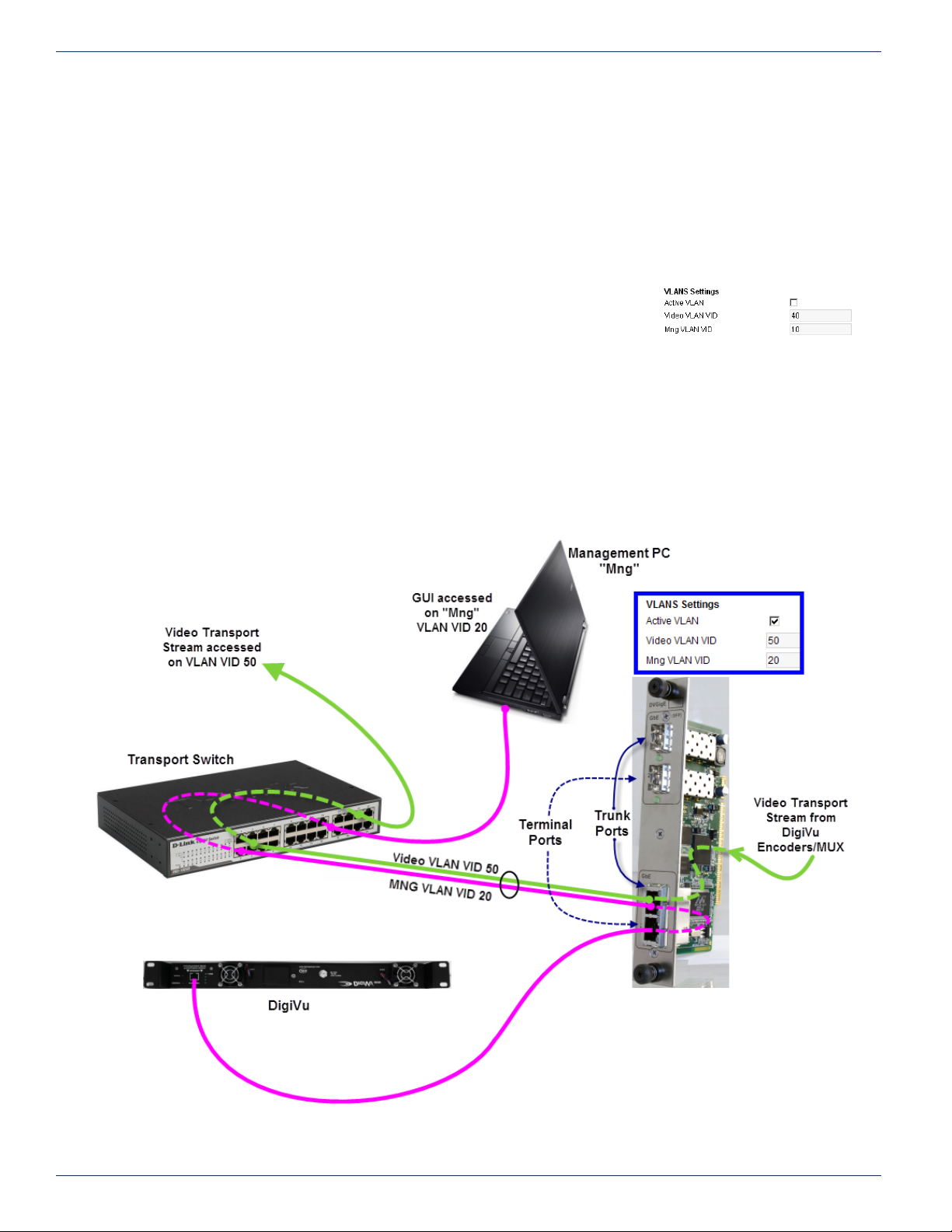
CHAPTER 11: IP OUTPUT TAB
11. 9.7 Row port: [1-65535]
Port number to use for transmission of FEC row data.
11. 9. 8 Use Col FEC only:
Use only Column FEC for the Pro-MPEG FEC
11.9.9 Interleaving Mode:
Congures which interleaving mode to use for FEC
11.10 VLANS Settings
The GbE output card supports automatic creation of 2 VLANs when this feature is
activated. See “11.3 Support for VLAN Tagging” on page 11-3 for further information
about the VLAN Tagging option. Figure 11-9 shows the implementation of VLANs to
assist in understanding and conguring the feature.
11.10.1 Active VLAN
This activates the use of VLANs for transport stream transmission and accessing the GUI over the Gigabit Ethernet card ports.
11.10. 2 Video VLAN VID
This is the Video VLAN ID
Figure 11-8: VLANS Settings Section
Figure 11-9: VLAN Setup and Operation
11-6 DigiVu® Series Multichannel MPEG-2/H.264 Encoder/Multiplexer with QAM &/or IP Output - Installation & Operation Manual
Page 77
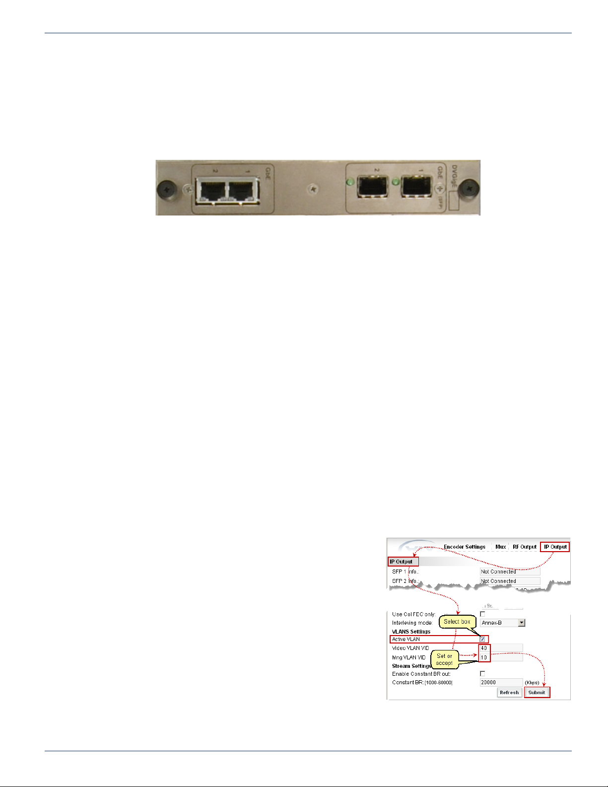
11.10. 3 Mng VLAN VID
This is the GUI VLAN ID
11.11 GbE Port Numbering
Physical ports on the Gigabit Ethernet card each have a number assigned for purposes of conguring VLANs as shown in
Figure 11-9 and described here:
1. Trunk Ports are both labeled #1 on the front panel.
Trunk ports will receive/transmit only tagged Ethernet packets which will be routed to their destination according to
their assigned VID. There is one each electrical and SFP (Small Form-Factor Pluggable) port which are identical
functionally and interchangeable depending on the type of interface required.
2. Terminal Ports are both labeled #2 on the front panel.
Terminal ports are connected to a device (such as the management port) that does not support VLAN tagging but
needs to be routed on a management VLAN. There is one each electrical and SFP port but the RJ45 port is typically
used in this case.
CHAPTER 11: IP OUTPUT TAB
Figure 11-10: GbE Card Port Numbering
11.12 Two VLANs Automatically Created
Enabling the VLAN option automatically creates 2 VLANs over which the streaming video and the management of the DigiVu
device may be accessed over a single physical connection but kept separate at the destination switch.
1. Video LAN
The GbE video multiplex exists on this virtual LAN (it is connected to the switch through an internal port and the card
connector). This means that the MUX output is connected to an internal switch in the GigE Card. MUX output then
ows to both physical trunk ports; the ports labeled #1. These ports reside on the internal GbE switch so either may
be used as the trunk output.
2. Management LAN
Both physical Ports #2 of the GbE card are congured on this Virtual LAN. Either of these ports connect to the
Management Ethernet port through a straight wired Cat5e cable however typically only the RJ45 electrical port is
used. These ports are mutually exclusive so only one or the other may be used.
11.12 .1 Quick Guide to VLAN Setup
a) Set up a remote external switch with VLAN support and
VLANs enabled for the GUI and streaming video.
b) On the DigiVu ‘IP Output’ tab select the Active VLAN check
box.
c) Set the VLAN VID for Mng (GUI) and Video VLAN VID to the
same VIDs used on the external switch.
d) Click Submit.
e) Connect the management IP port (from DigiVu Mini front
panel or the DiguVu 3RU back panel) to RJ45 GbE Port 2
on the GbE card using a short straight through Cat5e cable.
f) Connect one of the trunk ports labeled #1 (depends whether
you use copper or SFP) to a Trunk port on the external switch.
g) Connect a Management PC to the ‘Mng‘ management port at
the remote external switch and login to the GUI making sure
both the PC and DigiVu reside on the same subnet.
Figure 11-11: Activate and Congure VLAN
DigiVu® Series Multichannel MPEG-2/H.264 Encoder/Multiplexer with QAM &/or IP Output - Installation & Operation Manual 11-7
Page 78
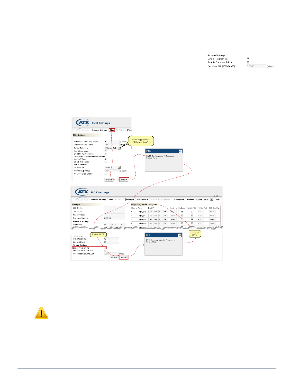
CHAPTER 11: IP OUTPUT TAB
h) Connect another PC or the receiving device to the dened video port at the external switch and set it
up to capture the video over IP as was congured at the ‘IP Output’ tab.
11.13 Stream Settings
11.13.1 Single Program TS:
This feature allows the creation of Single Program Transport Streams (SPTS) from the
IP output rather than all the programs being distributed in a single MPTS multiplex
with a single IP address. This is available to be selected only when the Ethernet output
alone is active. This setting is on the Mux tab. See “Output Selection:” on page 7-2 to select “Ethernet Only”. The conguration
of the addresses, dening the address as multicast and enabling FEC is done in a table available on this IP Output tab. Only
encoders that have been activated on the Encoder Settings tab will be available to congure. For information on that see
“Encoder Settings Tab” on page 6-1.
Figure 11-12: Stream Settings Section
Figure 11-13: Enable and Congure SPTS Feature
11.13. 2 Enable Constant BR Out:
Congures the multiplexer to output a constant bit stream at a dened data rate without regard to the actual payload data rate.
This may be dened if a STB or other receiving device requires a bit stream at a dened rate. If the payload is less than the
number dened here, null packets will be used to stuff the IP data stream to the dened output rate.
NOTE: This only works in MPTS mode.
11.13. 3 Constant BR: [1000-60000]
This is the CBR bit rate of the transport stream on the Ethernet network if a constant rate is desirable. Dening a bit rate higher
than the payload will result in null stufng of the transport stream to the bit rate specied here.
11-8 DigiVu® Series Multichannel MPEG-2/H.264 Encoder/Multiplexer with QAM &/or IP Output - Installation & Operation Manual
Page 79

NOTE: This only works in MPTS mode.
Buttons
11.14 Platform Control Buttons
CHAPTER 11: IP OUTPUT TAB
11.14.1 Refresh Button
This control reads the stored settings and refreshes the page with the values. This
also will read the card types installed and populate the display with the discovered
types. This is useful when a card type has been changed or a new card is installed. This is not a service affecting operation.
11.14. 2 Submit Button
NOTE: This is a service affecting operation.
This control applies all of the changes made on the ‘IP Output’ tab and makes the changes part of the working conguration of
the DigiVu system. If changes have been made click Submit button before navigating away from the page, to avoid all changes
being lost. This attribute may be used to throw away changes made if you change your mind.
Figure 11-14: Platform IP Control
DigiVu® Series Multichannel MPEG-2/H.264 Encoder/Multiplexer with QAM &/or IP Output - Installation & Operation Manual 11-9
Page 80

CHAPTER 11: IP OUTPUT TAB
This page intentionally left blank
11-10 DigiVu® Series Multichannel MPEG-2/H.264 Encoder/Multiplexer with QAM &/or IP Output - Installation & Operation Manual
Page 81

FIRMWARE UPGRADE & RECOVERY
12. Firmware Upgrade & Recovery
In this chapter we explain the rmware upgrade process and where to get rmware les. We also discuss the procedure for
recovering to a previous rmware version or resetting the username & password if it is ever necessary.
FYI: In this guide, reference to DigiVu infers DigiVu 3RU, DigiVu CD 3RU and DigiVu Mini 1RU
unless the model is specically stated. Reference to DVIS is synonymous with DigiVu as these
products run on the same rmware.
New system rmware for the DigiVu platforms is provided in an archive le format of .tgz in a zip container and will be made
available on the ATX Networks support site for each model of the DigiVu family, see “Where to Obtain Firmware Files” on page
12-3 to obtain the rmware. The DigiVu family uses a common rmware and it technically does not matter which support site
the rmware is obtained from. It is not necessary to un-compress the tgz package as the DigiVu has built-in facilities to accept
the le in tgz format. The tgz le is provided from ATX Networks support site in a zip format, so it will be necessary to un-zip
the le downloaded rst. The name of the zip le and the tgz le inside will be the same except for the extension and both will
be named with the rmware version number. If you require a program to unzip the le, an open source le archiver may be
obtained for free at the http://www.7-zip.org/download.html site.
CHAPTER 12: FIRMWARE UPGRADE & RECOVERY
12.1 Chapter Contents
• “Types of Firmware Files”
• “Identifying Current Firmware Version”
• “Exporting a Conguration”
• “Where to Obtain Firmware Files”
• “Firmware Upgrade Process”
• “System Recovery Process”
• “Restore a Conguration Export”
• “Username & Password Reset Process”
12.2 Types of Firmware Files
A brief description of the les that may be found on the support web sites.
12.2.1 System Upgrade/Recovery File
This is a le that is used to bring the DigiVu up to the latest rmware revision and is referred to as a rmware upgrade. This le
may be used even if the equipment has a very old version of rmware installed as it completely replaces all les on the DigiVu
platform and works with any previously installed version. This le can also be used to reinstall the latest rmware revision on
an already upgraded device if there is suspicion that the rmware might not be working as expected and this application of the
same le would be referred to as a system recovery. This is the most commonly installed le type and is installed in the same
manner regardless of the end requirement. The following attributes apply to this le type:
• Can be used to upgrade any rmware version or when existing version is unknown.
• Fully replaces existing rmware.
• Suitable only when unit is physically available (cannot be applied remotely).
• Used to recover network parameters, login credentials or after mis-conguration.
• IP parameters and login passwords are reset to factory default.
• Requires full re-conguration of all channel parameters.
12.2.2 Remote Upgrade
This le type may be applied to the equipment even if it is remotely located. This rmware may be installed over a limited range
of previous rmware so check the support site for qualifying existing versions.
• Usable for minor rmware changes. Check the support site for qualifying existing versions.
• Suitable when the unit is remotely located.
• IP parameters and login credentials are not changed.
DigiVu® Series Multichannel MPEG-2/H.264 Encoder/Multiplexer with QAM &/or IP Output - Installation & Operation Manual 12-1
Page 82
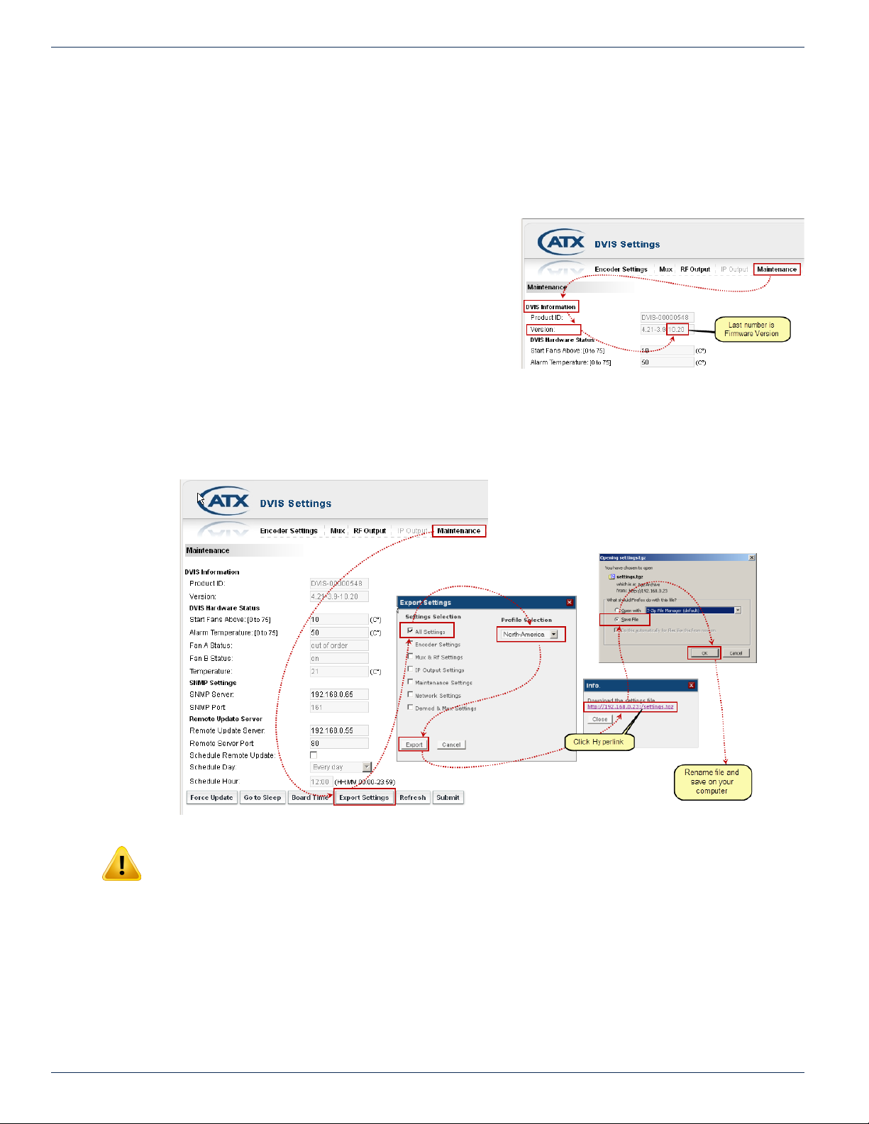
CHAPTER 12: FIRMWARE UPGRADE & RECOVERY
• Channel parameters are not changed.
12.2.3 Username and Password Reset File
It is possible to reset a lost username and password without losing the programmed conguration. A special le is available to
reset the username and password back to factory defaults (username: atx, password: atx). This le must be requested from
ATX Networks technical support.
12.3 Identifying Current Firmware Version
The currently installed rmware version is displayed in the DigiVu GUI
under the ‘Maintenance’ tab, as shown in Figure 12-1.
12.4 Exporting a Conguration
The DigiVu has the ability to export the programmed conguration as
a le, which could be kept as a backup or used for mass deployment
of a common conguration. It is suggested to export the conguration
prior to upgrading rmware but the exported settings may not be used
to restore after a rmware upgrade since system settings may be
incompatible between rmware versions. The settings le may only be
restored to a DigiVu with the same version rmware as the unit from which it originates. Making this backup is not service
affecting and it is recommended that the settings be exported and saved whenever the DigiVu system conguration changes.
The settings le is exported from the ‘Maintenance’ tab. Figure 12-2 illustrates what to do.
Figure 12-1: Identify the Current Firmware Version
Figure 12-2: Export Your Conguration
NOTE: If a rmware upgrade is undertaken, it will not be possible to use an exported conguration
made as a backup since features introduced in the newer rmware will render the backup le from
a previous rmware version incompatible. A backup taken will only be of use on a DigiVu with a
rmware version the same as the version from which it is taken, ie. if the rmware is ever reverted
back to the original version. Only use exported conguration les on a DigiVu of identical
rmware version.
12-2 DigiVu® Series Multichannel MPEG-2/H.264 Encoder/Multiplexer with QAM &/or IP Output - Installation & Operation Manual
Page 83

12.5 Where to Obtain Firmware Files
Firmware upgrade les are released by ATX Networks periodically to add features or to address potential issues with released
rmware operation. The rmware les, when released, will always be obtained from ATX Networks Technical Support.
If further information is required during any phase of the rmware upgrade, or you have concerns or questions about the
rmware or it’s applicability to your DigiVu, contact ATX Networks Digital Video Support.
12.6 Firmware Upgrade Process
The following rmware upgrade process is the general format that will be followed. Each rmware upgrade may have specic
criteria that will need to be adhered to and those criteria will be posted with the upgrade.
FYI: This manual does not contain specic up to date information for each release. Please read
the instructions posted with each rmware release on the support web site.
NOTE: With the exception of applying the remote upgrade le and password reset le, applying
system upgrade les will cause the loss of programmed settings. Record the conguration so it
may be re-programmed before applying a system upgrade/recovery le.
12.6.1 Save Firmware File to Management Computer
Save the le obtained in a convenient location on the Management Computer. The upgrade le is named with the same name
as the version of the upgrade although it may be contained in a zip wrapper. Extract the rmware le within the zip archive
and save it in a convenient location on the Management Computer. This recovery le is in .tgz format and is itself an archive
format. It should not be modied in any way or extracted further, though it may be renamed.
12.6.2 Direct Connect Management Computer to DigiVu
If connecting to your DigiVu directly through a cable, set the computer that you will use for the upgrade to the same subnet as
the DigiVu in order to access the GUI. For example, if the network address for the DigiVu is set to the factory default setting of
192.168.0.23 set the Management Computer to an address between 192.168.0.24 and 192.168.0.255
If you do not know how to set the Management Computer to the same subnet as the DigiVu, see “Connecting to the GUI” on
page 5-2 for a tutorial on setting the IP address.
For connecting to your remote DigiVu through the Internet use the usual procedure for your situation. This setting cannot be
specied here.
CHAPTER 12: FIRMWARE UPGRADE & RECOVERY
®
DigiVu® Series Multichannel MPEG-2/H.264 Encoder/Multiplexer with QAM &/or IP Output - Installation & Operation Manual 12-3
Page 84
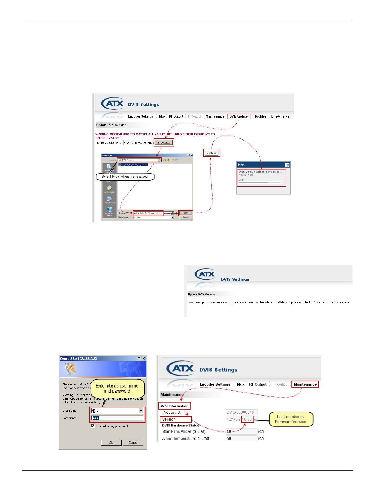
CHAPTER 12: FIRMWARE UPGRADE & RECOVERY
Figure 12-3: Upload Firmware
Figure 12-6: Login
12.6.3 Upload Firmware
1. Select the ‘DVIS Update’ tab. The ‘Update DVIS Version’ page will appear.
2. Click Browse, navigate to the folder on your computer where you saved the .tgz le and click Open. The le name
and location appear in the selection box.
3. Click Update to begin uploading the le to the DigiVu. See Figure 12-3.
4. A progress bar indicates the percentage le upload completion (0 to 100%).
5. When le upload is complete the unit will present the ‘Upload Done’ page, shown in Figure 12-4.
6. When the upload has nished, le installation
begins automatically. The amount of time
required for the rmware le installation
may vary depending on factors such as link
speed and type and size of upgrade le.
7. Close the browser window.
8. When installation has completed, the unit
reboots (indicated when the fans shut off for
Figure 12-4: Upload Done
a few seconds and then restart).
9. Wait 2 minutes after the fan restarts for the reboot to complete.
10. Open Internet Explorer and enter ‘http://192.168.0.23/site’ in the URL eld. When the login screen appears, enter atx
for both the Username and Password. The ‘Encoder Settings’ page appears.
Figure 12-5: Check New Firmware Version
12-4 DigiVu® Series Multichannel MPEG-2/H.264 Encoder/Multiplexer with QAM &/or IP Output - Installation & Operation Manual
Page 85

11. Select the ‘Maintenance’ tab and verify that ‘Version Number’ is the same as the number in the name of the rmware
upgrade le.
12. If the installed rmware version agrees with the name of the le, the rmware upgrade is complete.
12.7 System Recovery Process
NOTE: Do not depress the ‘RESET’ button unless you have the appropriate rmware le
available. This will cause your DigiVu to wait indenitely until the rmware is uploaded. There is no
cancel button for recovery mode and once recovery mode has begun, the appropriate rmware le
has to be uploaded to complete the recovery process.
12.7.1 Introduction
NOTE: All programmed settings will be lost. Record the conguration so it may be re-programmed
before applying the system recovery le.
System recovery is intended to restore the DigiVu system in case it is suspected that internal les have become corrupted and
that the GUI has become unresponsive. The Recovery Mode/Status is reached by pressing and holding, for several seconds,
the ‘Reset Button’ until the fans stop running. The button is located on the front panel of the DigiVu Mini or the back panel of
the DigiVu and DigiVu CD beside the Management IP port and is covered from the factory by a small adhesive dot to prevent
inadvertent use. One fan will start running again while the other will remain idle. In recovery mode, the IP address setting of
the Management IP port always reverts to 192.168.0.23 regardless of previously congured IP settings before recovery. Now
the appropriate rmware le has to be uploaded, typically the latest rmware version upgrade le.
CHAPTER 12: FIRMWARE UPGRADE & RECOVERY
NOTE: By default the DigiVu IP address will be reset to 192.168.0.23 so it will be necessary to
congure a computer on the same subnet to allow uploading the le, using an address between
192.168.0.24 and 192.168.0.255.
12.7.2 Obtain and Save Firmware Upgrade
Obtain the appropriate recovery rmware le and save it in a known location on the Management Computer. This le is in .zip
format and its name contains the version code for this upgrade.
Extract the rmware le within the zip archive and save it in a known location on the Management Computer. This le is in .tgz
format and is itself an archive format. It should not be modied in any way or extracted further.
12.7.3 Set Management PC Subnet
You will need to connect to your DigiVu directly through a cable, so set the computer that you will use for the upgrade to the
same subnet as the DigiVu in order to access the GUI. The network address for the DigiVu unit will be reset to the factory
default setting of 192.168.0.23 so congure the computer to an address between 192.168.0.24 and 192.168.0.255.
If you do not know how to set the Management Computer to the same subnet as the DigiVu, see “Connecting to the GUI” on
page 5-2 for a tutorial on setting the IP address.
12.7.4 Reset the DigiVu
NOTE: Do not depress the ‘RESET’ button unless you have the appropriate rmware le
available. This will cause your DigiVu to wait indenitely until the rmware is uploaded. There is no
cancel button for recovery mode and once recovery mode has begun, the appropriate rmware le
has to be uploaded to complete the recovery process.
Using a pen or similar small pointed object, press and hold the ‘RESET’ button on the front panel of the DigiVu Mini or the back
panel of the DigiVu or DigiVu CD for several seconds to place the unit in RESET/RECOVERY mode. You can recognise the
condition when both fans stop operating, then after a few seconds they restart (this assumes that the fans were running). Wait
about 1 minute more for the DigiVu to restart.
®
NOTE: In Recovery Mode, the DigiVu Management IP port reverts to 192.168.0.23.
DigiVu® Series Multichannel MPEG-2/H.264 Encoder/Multiplexer with QAM &/or IP Output - Installation & Operation Manual 12-5
Page 86
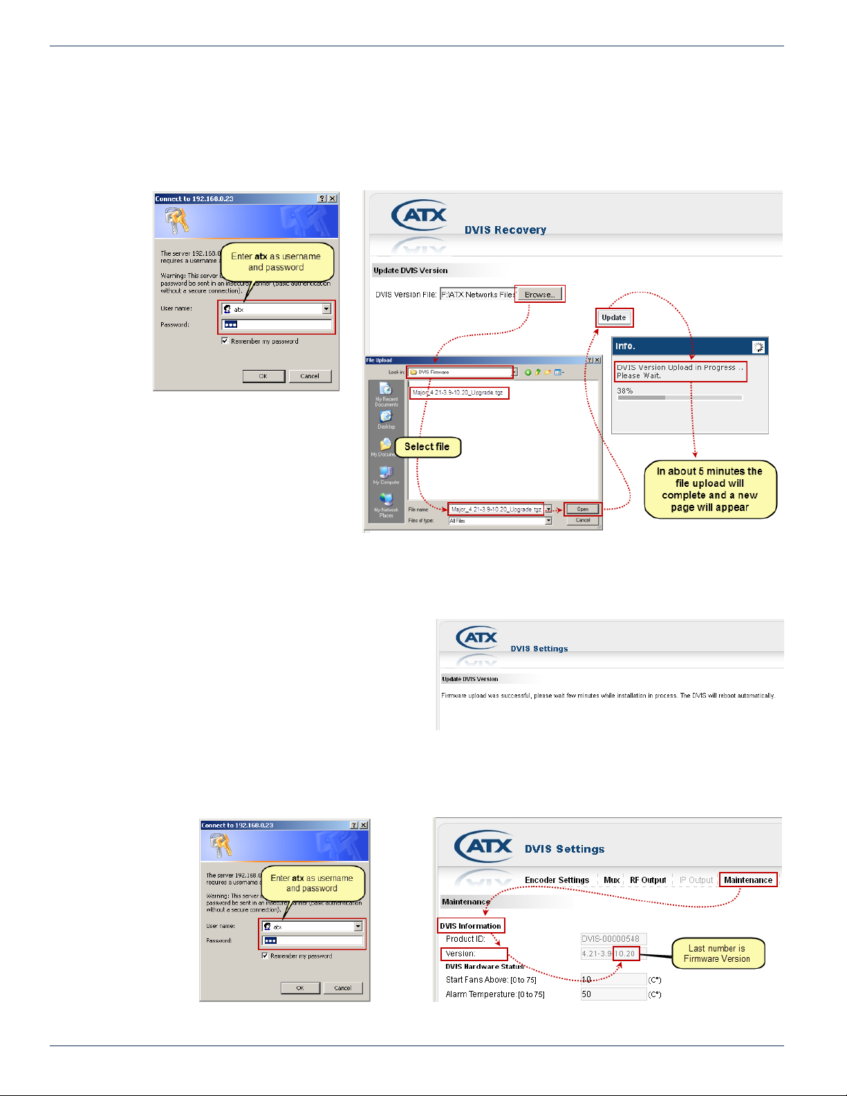
CHAPTER 12: FIRMWARE UPGRADE & RECOVERY
Figure 12-11: Check Firmware Version
12.7.5 Connect to GUI
1. Open an Internet Explorer browser window and enter http://192.168.0.23/site in the address eld.
2. When the login screen appears, enter atx for both the Username and Password, see Figure 12-7.
3. Upon validation of the login and password, the ‘DVIS Recovery’ page appears, see Figure 12-8.
Figure 12-7: Login
12.7.6 Upload Firmware
1. Click Browse, see gure Figure
12-8, navigate to the location of the
saved les and select the le. The
le name and location appear in the
selection box.
2. Click Update to begin uploading
the le to the unit. A progress bar
indicates the percentage completion (0 to 100%). When the upload is nished, the Upload Done page appears in the
web browser as shown in Figure 12-9 and le installation on the DigiVu begins automatically.
3. Close the web browser.
4. When installation has completed (which can
take several minutes), the unit reboots (indicated
when the fan shuts off for a few seconds and
then restarts). After a few seconds the second
fan restarts.
5. Wait an additional 90 seconds, reopen the web
browser and enter http://192.168.0.23/site in
the address eld. When the login screen appears,
enter atx for both the Username and Password,
see Figure 12-10. The ‘DVIS Encoder Settings’ page appears.
6. Click Maintenance and verify that ‘Version’ is the same as the name of the upgrade le, see Figure 12-11.
Figure 12-8: Restore System Firmware
Figure 12-9: Upload Done
Figure 12-10: Login
12-6 DigiVu® Series Multichannel MPEG-2/H.264 Encoder/Multiplexer with QAM &/or IP Output - Installation & Operation Manual
Page 87
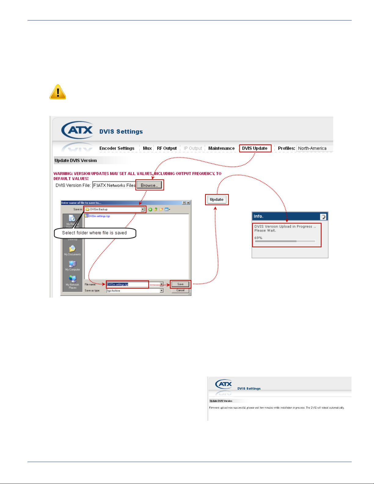
12.8 Restore a Conguration Export
If you saved an exported le or are performing a mass deployment of a number of DigiVu with identical congurations and
installed rmware, you can restore the saved conguration from the exported le. The le is in tgz format and would have been
named settings.tgz if you accepted the name that the DigiVu suggested when exported.
NOTE: Only install exported conguration les on DigiVu units with identical rmware version as
the unit from which the conguration le originated.
Restore an exported le in the same manner as a rmware upgrade from the ‘DVIS Update’ tab. See Figure 12-12.
CHAPTER 12: FIRMWARE UPGRADE & RECOVERY
Figure 12-12: Restore an Exported Conguration
1. Select the ‘DVIS Update’ tab. The ‘Update DVIS Version’ page will appear.
2. Click Browse, navigate to the folder on your computer where you saved the settings.tgz le (or whatever name you
may have given it) and click Open. The le name and location appear in the selection box.
3. Click Update to begin uploading the le to the DigiVu. A progress bar indicates the percentage le upload completion
(0 to 100%).
4. When le upload is complete the DigiVu will present the ‘Upload Done’ page, as shown in Figure 12-13.
5. When the upload has nished, le installation
begins automatically.
6. Close the browser.
7. When le installation has completed (which can
take about 1 minute), the unit reboots (indicated
when the fans shut off for a few seconds and
then restart).
Figure 12-13: Upload Done
8. Wait 2 minutes after the fan restarts for the
reboot to complete.
9. Open Internet Explorer and enter one of the following in the browser URL eld as appropriate:
a) Enter http://192.168.0.23/site if the exported IP address was set to the default IP address setting.
DigiVu® Series Multichannel MPEG-2/H.264 Encoder/Multiplexer with QAM &/or IP Output - Installation & Operation Manual 12-7
Page 88

CHAPTER 12: FIRMWARE UPGRADE & RECOVERY
b) Enter the IP address of the DigiVu that was saved in the exported le.
c) Enter the original IP address of the target DigiVu receiving the le if ‘Network Settings’ was not part
of the restoration le.
10. When the login screen appears, enter one of the following in the browser URL eld as appropriate:
a) Enter atx for both the username and password if the default DigiVu settings had been restored.
b) Enter the username and password of the DigiVu that was saved in the exported le.
c) Enter the original username and password of the target DigiVu receiving the le if ‘Network Settings’
was not part of the restoration le.
11. The DVIS ‘Encoder Settings’ page appears.
12. Conguration settings dened by the settings.tgz le have been restored.
12.9 Username & Password Reset Process
NOTE: Do not depress the ‘RESET’ button unless you have the appropriate rmware le
available. This will cause your DigiVu to wait indenitely until the rmware is uploaded. There is no
cancel button for RESET mode and once begun, the appropriate rmware le has to be uploaded
to complete the process.
NOTE: The password reset le may be obtained from ATX Networks technical support group,
see “Contact ATX Networks” on page 15-1 for phone numbers and email address.
12 .9.1 Introduction
The Username/Password reset process is intended to restore the DigiVu factory username and passwords in case it is has
been changed then lost or forgotten. After this process, the login credentials will be returned to factory settings but all other
settings will be unchanged. The password recovery mode is reached by pressing and holding, the ‘RESET’ button for several
seconds, until the fans stop running. The button is located on the front panel of the DigiVu Mini or the back panel of the DigiVu
and DigiVu CD beside the Management IP port and is covered from the factory by a small adhesive dot to prevent inadvertent
use. One fan will start running again while the other will remain idle. In reset mode, the IP address setting of the Management
IP port always reverts to 192.168.0.23 regardless of previously congured IP settings before reset, then using the factory
default IP address, the appropriate rmware le is uploaded.
NOTE: By default the DigiVu IP address will be reset to 192.168.0.23 so it will be necessary to
congure a computer on the same subnet to allow uploading the le, using an address between
192.168.0.24 and 192.168.0.255.
12.9.2 Obtain and Save Password Reset File
Obtain the appropriate recovery rmware le from ATX Networks and save it in a known location on the Management Computer.
This le is in .zip format and the version you are given will depend on the rmware version installed on your equipment.
Extract the rmware le within the zip archive and save it in a known location. This le is in .tgz format and is itself an archive
format. It should not be modied in any way or extracted further.
12.9.3 Set Management PC Subnet
During this process, the network address for the DigiVu unit will be reset to the factory default setting of 192.168.0.23 so
you will need to connect to your DigiVu directly through a crossover Ethernet cable. Set the computer that you will use for
the recovery to the same subnet as the DigiVu in order to access the GUI, conguring the computer to an address between
192.168.0.24 and 192.168.0.255. If you do not know how to change the Management Computer subnet, see “Connecting to
the GUI” on page 12-5 for a tutorial.
12-8 DigiVu® Series Multichannel MPEG-2/H.264 Encoder/Multiplexer with QAM &/or IP Output - Installation & Operation Manual
Page 89

CHAPTER 12: FIRMWARE UPGRADE & RECOVERY
12.9.4 Reset the DigiVu
®
NOTE: Do not depress the ‘RESET’ button unless you have the Password Reset rmware le
available. This will cause your DigiVu to wait indenitely until the rmware is uploaded. There is no
cancel button for recovery mode and once recovery mode has begun, the appropriate rmware le
has to be uploaded to complete the process.
Using a pen or similar small pointed object, press and hold the ‘RESET’ on the front panel of the DigiVu Mini or the back
panel of the DigiVu or DigiVu CD for approximately 5 to 10 seconds to place the unit in RESET mode. You can recognise the
condition when both fans stop operating, then after a few seconds they restart (this assumes that the fans were running before
reset). Wait about 1 minute for the DigiVu to restart.
NOTE: In Reset Mode, the DigiVu Management IP port reverts to 192.168.0.23.
12.9.5 Connect to GUI
1. Open an Internet Explorer browser window and enter http://192.168.0.23/site in the address eld.
2. When the login screen appears, enter atx for both the Username and Password, see Figure 12-14.
3. Upon validation of the login and password, the ‘DVIS Recovery’ page appears.
12.9.6 Upload Password Reset Firmware
1. Click Browse, navigate to the location of the saved les and select the le. The le name and location appear in the
selection box, see Figure 12-15.
Figure 12-14: Login
Figure 12-15: Upload Password Reset Firmware
2. Click Update to begin uploading the le to the unit. A progress bar indicates the percentage completion (0 to 100%)
but it happens very fast so it is easy to miss.
When the upload is nished, the ‘Upload Done’
page appears in the web browser as shown in
Figure 12-16 and le installation begins
automatically.
3. Close the web browser.
4. When installation has completed (which can
take several minutes), the unit reboots (indicated
DigiVu® Series Multichannel MPEG-2/H.264 Encoder/Multiplexer with QAM &/or IP Output - Installation & Operation Manual 12-9
Figure 12-16: Upload Done
Page 90
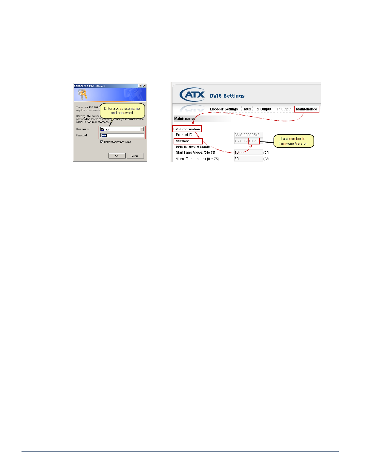
CHAPTER 12: FIRMWARE UPGRADE & RECOVERY
when the fans shut off for a few seconds and then restart).
5. Wait an additional 90 seconds, reopen the web browser and enter http://192.168.0.23/site or the original IP address
in the address eld. If the IP address was other than the factory set address, the original will be restored. When the
login screen appears, enter atx for both the Username and Password, see Figure 12-17. The ‘DVIS Encoder Settings’
page appears, see Figure 12-18.
Figure 12-17: Login
Figure 12-18: Check Firmware Version
6. Click Maintenance from the menu bar and verify that ‘Version’ has not changed.
7. Change the username and password to whatever is required by your system. For details on doing that, see “9.8.1
Change Username & Password” on page 9-7.
12-10 DigiVu® Series Multichannel MPEG-2/H.264 Encoder/Multiplexer with QAM &/or IP Output - Installation & Operation Manual
Page 91
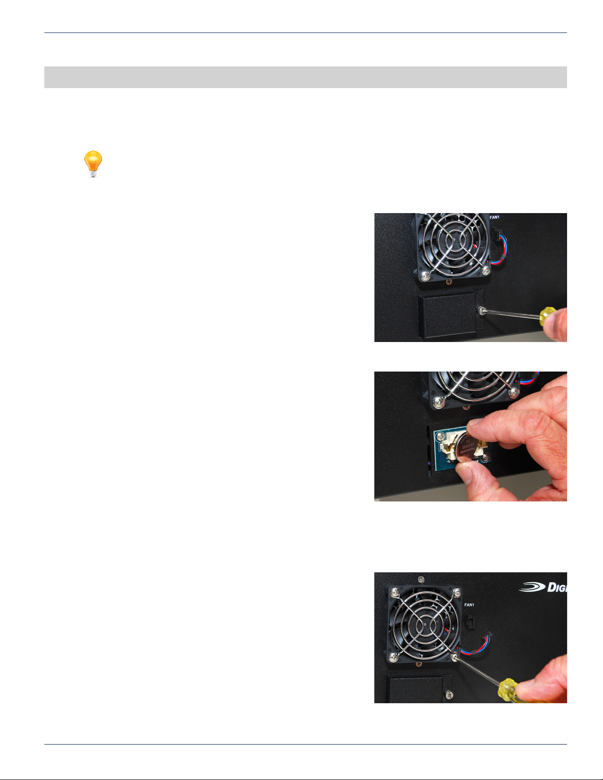
FIELD REPLACEMENTS
13. Field Replacements
FYI: Reference to DigiVu infers both DigiVu 3RU, DigiVu CD 3RU and DigiVu Mini 1RU unless
specically stated.
13.1 Field Replacement of Realtime Clock Battery
All DigiVu models have a realtime backup battery access door on the
front panel. This battery maintains continuity of the clock on the DigiVu
main board in the event of power outages. The CMOS battery is Lithium
and has an expected life of 20+ years under normal system operation.
The DigiVu is shown but the procedure is the same for DigiVu Mini.
13.1.1 Remove Battery
1. Remove the battery cover with a #1 Phillips screwdriver.
2. Gently remove the battery from its retainer clips.
CHAPTER 13: FIELD REPLACEMENTS
13.1.2 Replace Battery
1. Replace the battery with a 3 volt CR 2032 or exact replacement
type.
2. Snap the battery into the retainer clips.
3. Replace the door and retain with the Phillips screw.
13.1.3 Dispose of Battery
Recycle or dispose of batteries in accordance with the battery
manufacturer’s instructions and local/national disposal and recycling
regulations. If you are located in North America, please call
1-800-8-BATTERY or go to the website at www.call2recycle.org for
information on recycling or disposing of your used battery.
13.2 Field Replacement of Cooling Fans
13.2.1 Remove Fan
1. Disconnect the fan connector by gently pulling on the wires.
The connector is retained only by friction clips.
2. Using a #2 Phillips screwdriver, remove the four screws holding
the fan in place.
3. Remove the nger guard for reuse.
Figure 13-1: Remove Battery Cover
Figure 13-2: Remove Battery
13.2.2 Replace Fan
1. Hold the fan in position with the nger guard installed so the fan
rotates freely(do not ip it inside out), insert the four retaining
screws and tighten using the #2 Phillips screwdriver.
2. Insert the connector into the adjacent receptacle and seat the
connector fully into the receptacle.
DigiVu® Series Multichannel MPEG-2/H.264 Encoder/Multiplexer with QAM &/or IP Output - Installation & Operation Manual 13-1
Figure 13-3: Disconnect and Remove Cooling Fan
Page 92
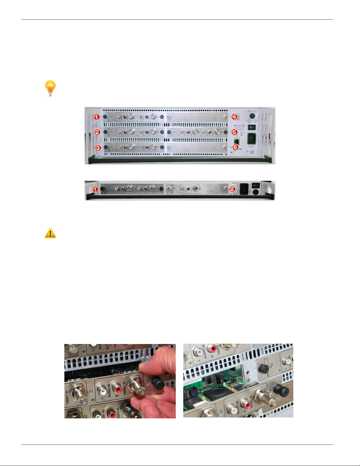
CHAPTER 13: FIELD REPLACEMENTS
and Gently Pull Card Out
13.3 Field Replacement of Plug-in Cards
All plug-in cards are installed in a slot on the rear panel which are numbered 1 through 5 plus AUX (6th slot) on the DigiVu and
DigiVu CD, see Figure 2-13, and numbered 1 & 2 on the DigiVu Mini, see Figure 2-14. Be careful to align the circuit board of
the card with the internal card guides when re-inserting the cards.
FYI: See the card support table in “2.7.1 Card Slot Support” on page 2-8 for guidance in
installing cards into compatible slots.
Figure 13-4: DigiVu® 3RU Rear Panel
NOTE: The 6th card slot in the DigiVu 3RU platforms is for power only to cards which do not
require management, as this slot does not show up in the GUI. Currently, this slot is exclusively
used for the 2-Way A/V Splitter card but the A/V Splitter card may be installed in any slot if required.
13.3.1 Card Removal
1. Disconnect any cables attached to the card.
2. Loosen the thumbscrews at the left and right end of the card.
3. Gently slide the card out of the slot. See Figure 13-6.
13.3.2 Card Insertion
1. Align the card edges with the internal metal guides inside the card slot.
2. Gently slide the card into the slot until the rear edge of the card is seated in the connector at the back of the card
slot. See Figure 13-7.
3. Tighten the thumbscrews at the left and right end of the card.
4. Re-attach any cables that were removed.
Figure 13-5: DigiVu® Mini 1RU Rear Panel
Figure 13-6: Release Screws on Both Card Ends
13-2 DigiVu® Series Multichannel MPEG-2/H.264 Encoder/Multiplexer with QAM &/or IP Output - Installation & Operation Manual
Figure 13-7: To Replace - Align Card with Internal
Metal Guides
Page 93

TROUBLESHOOTING
14. Troubleshooting
This chapter lists the error codes that may be given by the DigiVu device under some circumstances. These codes may be
used to better understand the problem that was encountered and to help the ATX support engineer to assist in troubleshooting
the equipment problem.
14.1 Error Codes
The following chart displays the Error Codes that may appear in the GUI web browser.
Error code Operation Error description
404 HTTP Cannot load page as requested
500 HTTP Unknown HTTP request
502 HTTP Unknown POST request
503 Conguration Unknown A/V port
504 Conguration Cannot access shared memory
506 Conguration Cannot open conguration le
507 TS Analyze NO input TS in demodulator
508 TS Analyze Cannot nd PAT (PID 0)
509 TS Analyze Cannot nd TS information
CHAPTER 14: TROUBLESHOOTING
HTTP/1.0 200 _001 - System Is
Congured For Add & Drop But There
Is No Demod Card Present
DigiVu® Series Multichannel MPEG-2/H.264 Encoder/Multiplexer with QAM &/or IP Output - Installation & Operation Manual 14-1
Page 94

CHAPTER 14: TROUBLESHOOTING
This page intentionally left blank
14-2 DigiVu® Series Multichannel MPEG-2/H.264 Encoder/Multiplexer with QAM &/or IP Output - Installation & Operation Manual
Page 95

SERVICE & SUPPORT
15. Service & Support
15.1 Contact ATX Networks
Please contact ATX Technical Support for assistance with any ATX products. Please contact ATX Customer Service to obtain
a valid RMA number for any ATX products that require service and are in or out-of-warranty before returning a failed module
to the factory.
DIGITAL VIDEO TECHNICAL SUPPORT
Tel: (905) 428-6068
Toll Free: (800) 565-7488 (USA & Canada only)
► Press *3 for Technical Support
►Then press 1 for Digital Video Products (DVIS, DigiVu, UCrypt, VersAtivePro)
Email: [email protected]
CUSTOMER SERVICE
ATX Networks
1-501 Clements Road West
Ajax, ON L1S 7H4 Canada
CHAPTER 15: SERVICE & SUPPORT
Tel: (905) 428-6068
Toll Free: (800) 565-7488 (USA & Canada only)
► Press *1 for Customer Service
Fax: (905) 427-1964
Toll Free Fax: (866) 427-1964 (USA & Canada only)
Web: www.atxnetworks.com
Email: [email protected]
15.2 Warranty Information
All of ATX Networks’ products have a 1-year warranty that covers manufacturer’s defects or failures.
DigiVu® Series Multichannel MPEG-2/H.264 Encoder/Multiplexer with QAM &/or IP Output - Installation & Operation Manual 15-1
Page 96

1-501 Clements Road West, Ajax, ON L1S 7H4 Canada
Tel +1 (905) 428-6068 Toll Free +1 (800) 565-7488
Fax +1 (905) 427-1964 Toll Free Fax +1 (866) 427-1964
www.atxnetworks.com [email protected]
Printed in Canada Rev. 07/17 (ANW0986)
 Loading...