

Page 1

End-of-Sale as of
March 31, 2017
DigiVu® II
DigiStream
®
VersAtive
Patent Pending
1RU
HARDWARE INTERFACE MANUAL
Pro
www.atxnetworks.com
www.atxnetworks.com
Page 2

General Guide Notes
Document Number ANW1080
Manual Release Date August 4 2016
Cross Reference Hyperlink Usage
Hyperlinks are used liberally throughout the guide to assist the reader in nding related information if the reader is viewing the
Adobe PDF le directly. Hyperlinks may be identi ed by their blue text. Most links are to related pages within the document,
but some reference outside documents if the reader needs that additional information. The Table of Contents is entirely
hyperlinked and bookmarks are available but the bookmark feature must be turned on in your Reader application.
Symbol Usage
Throughout the manual, some symbols are used to call the readers attention to an important point. The following symbols are
in use:
NOTE: This symbol usage will call the reader’s attention to an important operation feature of the
equipment which may be safety related or may cause a service outage.
FYI: This symbol indicates that there is helpful related information available in this note or
elsewhere in the guide.
Although every effort has been taken to ensure the accuracy of this document it may be necessary, without notice, to make amendments or correct omissions.
Speci cations subject to change without notice.
VersAtive®Pro and DigiVu® II are registered trademarks of ATX in the United States and/or other countries. Products or features contained herein may be covered by one or more U.S. or foreign
patents. SUPERMICRO®, HDMI®, Adobe® Flash®, Microsoft® Windows® and other non-ATX product and company names mentioned in this manual are the property of their respective companies.
Page 3

TABLE OF CONTENTS
End-of-Sale as of
March 31, 2017
GENERAL GUIDE NOTES ....................................................ii
1. DEVICE OVERVIEW .................................................... 1-1
1.1 Chapter Contents ................................................. 1-1
1.2 Front Panels ..................................................... 1-1
1.3 Device Initial Conguration .......................................... 1-2
1.4 System Power Supplies ............................................ 1-3
1.5 Support for IPMI .................................................. 1-4
2. CAPTURE CARDS ..................................................... 2-1
2.1 Chapter Contents ................................................. 2-1
®
2.2 1 Channel - HDMI
2.3 1 Channel - SDI .................................................. 2-2
2.4 2 Channel - SDI .................................................. 2-2
2.5 4 Channel - SDI .................................................. 2-2
2.6 4 Channel - CVBS ................................................ 2-3
3. REAR PANELS ........................................................ 3-1
3.1 Chapter Contents ................................................. 3-1
3.2 Small Chassis Rear Panel .......................................... 3-1
3.3 Medium Chassis Rear Panel ........................................ 3-1
3.4 Grande Chassis Rear Panel ........................................ 3-2
3.5 Redundant Power Supply .......................................... 3-2
3.6 General Rear Panel Connections ..................................... 3-2
3.7 DigiStream Rear Panels ............................................ 3-3
®
3.8 DigiVu
3.9 VersAtive
II Rear Panels ............................................. 3-4
®
Pro Rear Panels ......................................... 3-5
or Component or CVBS ............................. 2-1
4. INSTALLATION ........................................................ 4-1
4.1 Chapter Contents ................................................. 4-1
4.2 Preparation for Installation .......................................... 4-1
4.3 Precautions ...................................................... 4-1
4.4 General Mechanical ............................................... 4-2
4.5 Gigabit Ethernet Ports ............................................. 4-2
4.6 Install the Chassis in a Rack. . . . . . . . . . . . . . . . . . . . . . . . . . . . . . . . . . . . . . . . . 4-3
4.7 Equipment Safety Grounding ........................................ 4-7
4.8 Power Supplies ................................................... 4-8
4.9 Ethernet Cabling ................................................. 4-10
5. STARTUP ............................................................ 5-1
5.1 Chapter Contents ................................................. 5-1
5.2 Management Computer ............................................ 5-1
5.3 Connecting to Your Computer . . . . . . . . . . . . . . . . . . . . . . . . . . . . . . . . . . . . . . . 5-1
VersAtive®Pro, DigiVu® II, DigiStream – 1RU Hardware Interface Manual iii
Page 4

GENERAL GUIDE NOTES
6. SAFETY ............................................................. 6-1
7. SERVICE & SUPPORT .................................................. 7-1
7.1 Contact ATX Networks ............................................. 7-1
7.2 Warranty Information .............................................. 7-1
iv VersAtive®Pro, DigiVu® II, DigiStream – 1RU Hardware Interface Manual
Page 5
DEVICE OVERVIEW
1. Device Overview
The VersAtive®Pro, DigiVu® II and DigiStream 1RU series, referred to as Devices in this manual, are built in identical chassis
but with different input and processing capabilities. Each model, while very similar in layout, may be identi ed by its unique
from panel labelling.
• VersAtivePro is a transcoder using IP input content (but may also have Analog or SDI Capture Cards eld installed).
• DigiVu II is an encoder using Analog and SDI input Capture Cards for content.
• DigiStream is a EPG creation and content streaming device (but may also have Analog Capture Cards installed).
Installation and network and Capture Card connections for each device are similar and are covered in this manual.
1.1 Chapter Contents
• “Front Panels”
• “Device Initial Con guration”
• “System Power Supplies”
• “Support for IPMI”
CHAPTER 1: DEVICE OVERVIEW
1.2 Front Panels
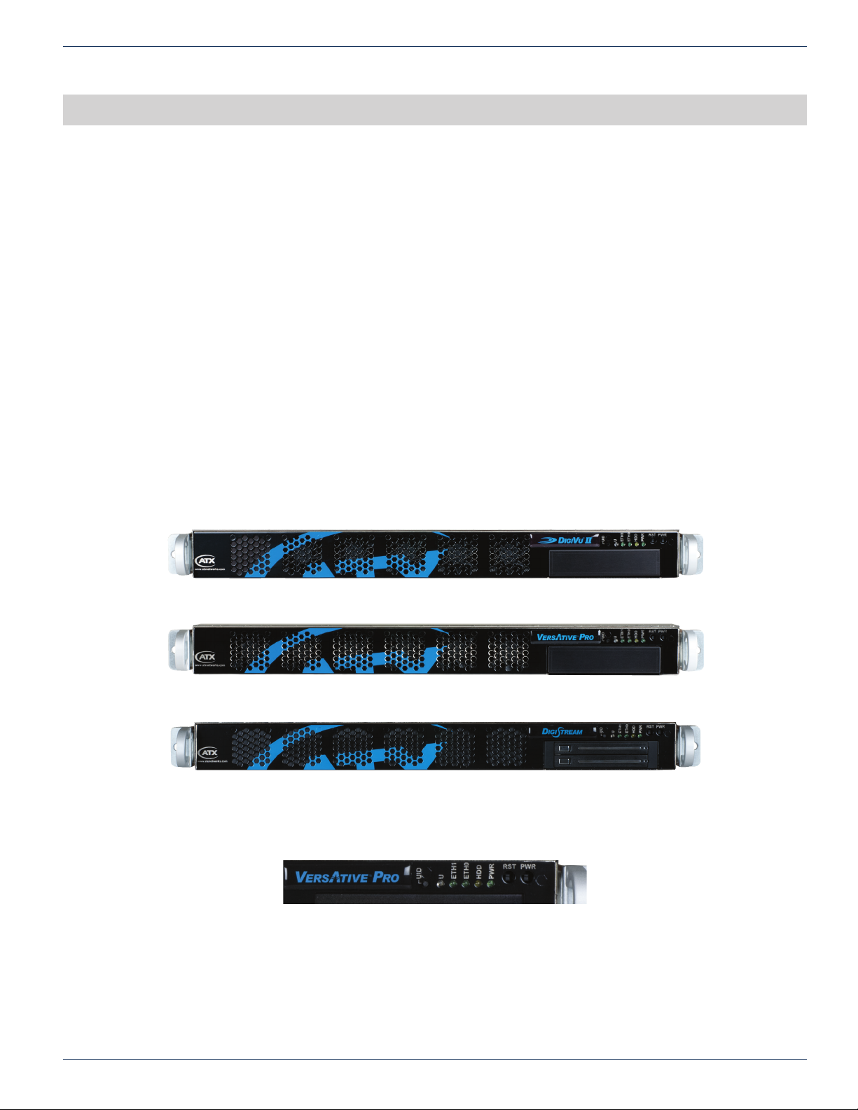
The front panel is common to all 1RU products with the exception of the product name.
1.2.1 Controls & Indicators
Figure 1-1: DigiVu® II Front Panel
Figure 1-2: VersAtive®Pro Front Panel
Figure 1-3: DigiStream Front Panel
Figure 1-4: Front Controls & Indicators
The products are designed to be plug and play and will be in a powered on state when the power cord is plugged in. There
may be instances where it is desired to reboot or power down the devices manually and recessed switches to enable that are
located on the front panel. Indicator lights are provided to allow monitoring of errors and alarms, See Table 1.2a for functional
descriptions of front panel controls and indicators.
VersAtive®Pro, DigiVu® II, DigiStream – 1RU Hardware Interface Manual 1-1
Page 6

CHAPTER 1: DEVICE OVERVIEW
Table 1.2a: Front Panel Controls and Indicators
Panel Label Function Description
UID Button Universal Identi er: A switch that will turn on the adjacent “U” light.
U Indicator LED
Blue
HDD Indicator LED
Green
PWR Indicator LED
Green
RST Recessed Button Used to reboot the encoder.
PWR Recessed Button The main power switch is used to apply or remove power to the encoder. Activating this
Universal Information LED: The Universal Information BLUE LED is used to indicate
fan failure, power failure, overheat condition, or to identify the unit within a large rack
installation. This may be activated by the IPMI or front panel button.
State Indication:
• Fast Blinking Red (1 per sec) - Fan Failure
• Solid Red - CPU Overheated
• Slow Blinking Red (1 per 4 sec) - Power Failure
• Solid Blue - Local UID Button Depressed
• Blinking Blue - IPMI Activated UID
Note: Deactivating the UID LED must be performed in the same way it was activated.
(If the UID LED was activated via IPMI, you can only turn the LED off via IPMI and not
with the UID button.)
Indicates SSD/HDD drive activity when ashing.
Indicates power is being supplied to the system’s power supply units. This LED should
be illuminated when the system is operating.
switch effectively turns the encoder off but keeps standby power supplied to the system.
You must unplug the system before servicing. Press again to power up.
1.3 Device Initial Confi guration
NOTE: Each individual Device must have default Management (eth0) port IP address changed
from 192.168.0.23 before connecting them to the Management Switch.
Each of the Devices are factory con gured with identical eth0 Management Port IP addresses. It is important to understand
that the standard ATX Networks default IP address of 192.168.0.23 for management is assigned to all products. Before
connecting each management port to the management switch, the IP addresses must be re-con gured.
1-2 VersAtive®Pro, DigiVu® II, DigiStream – 1RU Hardware Interface Manual
Page 7
1.4 System Power Supplies
1.4.1 Standard AC Power Supply
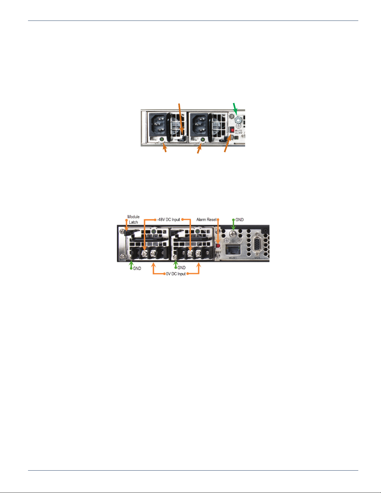
Each Device chassis includes a high reliability, high-efciency power supply, Figure 1-5, rated at 1620 Watts, and optionally,
one similar redundant backup power supply. In the unlikely event your power supply fails, replacement is simple and can be
accomplished without tools. See “4.8 Power Supplies” on page 4-8 for connection information.
CHAPTER 1: DEVICE OVERVIEW
1.4.2 Optional DC Power Supply
Optional DC power supplies may be ordered and operate on DC -40 to -72 Volts. See “4.8 Power Supplies” on page 4-8 for
connection information.
Removal Latch
Power Indicators
Figure 1-5: Redundant AC Power Supplies
Safety Ground
Mute Alarm
Figure 1-6: Redundant DC Power Supplies
VersAtive®Pro, DigiVu® II, DigiStream – 1RU Hardware Interface Manual 1-3
Page 8

CHAPTER 1: DEVICE OVERVIEW
1.5 Support for IPMI
The Intelligent Platform Management Interface is an standards based interface used by some system administrators to
remotely manage server hardware in an out of band fashion, that is irrespective of the installed operating system or BIOS of
the sever. Each VersAtivePro, DigiStream or DigiVu II platform has a dedicated IPMI network port enabled with DHCP. IPMI
Version 2.0 has been implemented on all VersAtivePro or DigiVu II products. More information may be obtained from the
SUPERMICRO
• SUPERMICRO
• The IPMI User Guides http://www.supermicro.com/manuals/other/Embedded_BMC_IPMI.pdf
• IPMIView Software Manual http://www.supermicro.com/manuals/other/IPMIView20.pdf
• Command Line Interface tool ftp://ftp.supermicro.com/utility/SMCIPMITool/SMCIPMITool_User_Guide.pdf
1.5.1 IPMI Dedicated LAN LEDs
In addition to the Gigabit Ethernet ports, an IPMI Dedicated LAN is also located on the
Backplane. The amber LED on the right of the IPMI LAN port indicates activity, while the
green LED on the left indicates the speed of the connection, Figure 1-7.
®
support site or the following links to the available IPMI software and manuals.
®
IPMIview software ftp://ftp.supermicro.com/utility/IPMIView/
http://www.supermicro.com/manuals/other/SMT_IPMI_Manual.pdf
NOTE: Security measures should be taken if traffi c from IPMI managed equipment is connected
with Internet access. For more information see https://www.us-cert.gov/ncas/alerts/TA13-207A
Figure 1-7: IPMI LAN Indicator
1-4 VersAtive®Pro, DigiVu® II, DigiStream – 1RU Hardware Interface Manual
Page 9
CAPTURE CARDS
3
4
5
7
7
8
8
9
9
10
12
13
14
14
15
15
Analog RGB In
Composite In
R In
G In (Comp In)
B In
Unbalanced
Analog Audio In
Left Audio In
Right Audio In
Ports 3, 4 & 5 Not Used
Ports 12 & 13 Not Used
HDMI Out Port Not Used
HDMI 4:2:2 Input
2. Capture Cards
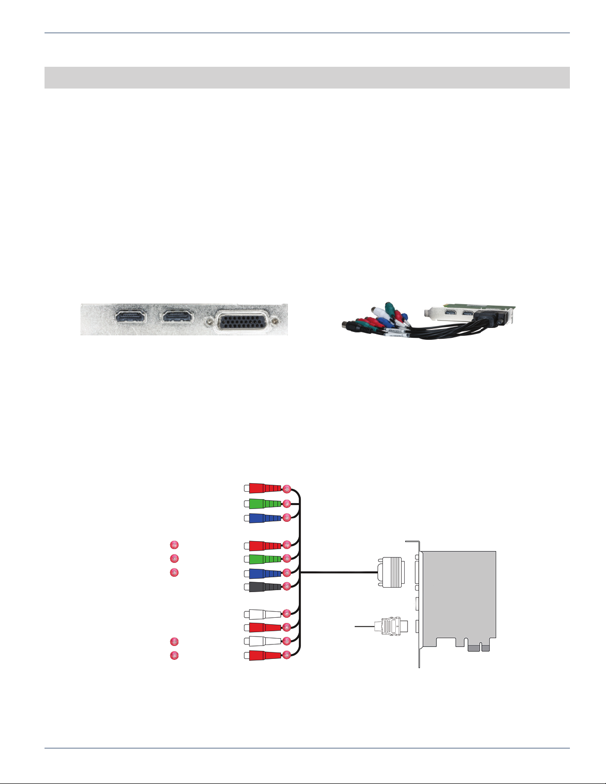
Capture Cards are used to ingest analog video/audio and SDI inputs to the Devices. They may be provided with some encoder
models as factory ordered or added in the eld. The input connections are not silk screened as to their function and not all
connections are used, so this guide will show which ports to use.
2.1 Chapter Contents
• “1 Channel - HDMI® or Component or CVBS”
• “1 Channel - SDI”
• “2 Channel - SDI”
• “4 Channel - SDI”
• “4 Channel - CVBS”
2.2 1 Channel - HDMI® or Component or CVBS
CHAPTER 2: CAPTURE CARDS
HDMI® - Component - CVBS Input Card
Multi-Input Card With Adapter Cable
Part Numbers: DigiStream DS-1HDA
Offered in: DigiVu II DVT1HDMIIP
DigiStream DSLI20-H0, DSLI20-HH, DSI40-H0, DSI40-HH
Single input
• HDMI digital with embedded audio on standard HDMI connector.
• Component Video on RCA with unbalanced stereo audio on RCA (BNC Adapters provided).
• Composite Video Baseband (CVBS) with unbalanced stereo audio on RCA (BNC Adapters provided).
VersAtive®Pro, DigiVu® II, DigiStream – 1RU Hardware Interface Manual 2-1
Multi-Input Card - Adapter Cable Connections
Page 10

CHAPTER 2: CAPTURE CARDS
Not Used
Not Used
Not Used
HD SDI #1
HD SDI #2
HD SDI #1
HD SDI #2
HD SDI #3
HD SDI #4
2.3 1 Channel - SDI
1
6
1 Channel SDI Input Card
Offered in: DigiVu II DVT1SDIIP
One input
• HD/SD SDI with embedded audio on BNC female jack.
2.4 2 Channel - SDI
2 Channel SDI Input Card
Offered in: DVT2SDIIP, DVT6SDIIP
Two inputs
• HD/SD SDI with embedded audio on BNC female jacks.
Not Used
Not Used
Not Used
SDI
1-Ch SDI Input Card Connections
2Ch SDI Input Card Connections
2.5 4 Channel - SDI
4 Channel SDI Input Card
Offered in: DVT4SDIIP, DVT6SDIIP
Four inputs:
• HD SDI with embedded audio on BNC female jacks (w/adapter cables).
4 Channel SDI Input Card With Adapter Cables
Not Used
4Ch-SDI Input Card Connections
Not Used
Not Used
Not Used
Not Used
2-2 VersAtive®Pro, DigiVu® II, DigiStream – 1RU Hardware Interface Manual
Page 11
2.6 4 Channel - CVBS
Audio #1
Audio #2
Audio #3
Audio #4
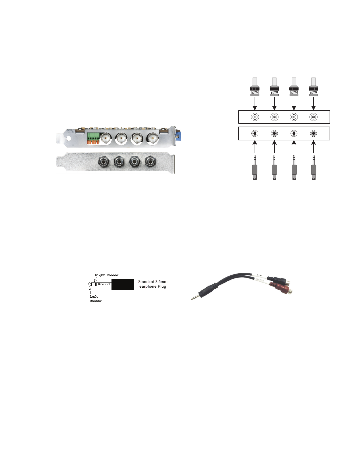
Part Number: DigiStream DS-4SDA
Offered in: DigiVu II DVT4SDAIP
DigiStream DSI40-S0, DSLI20-S0
Four inputs:
• Composite Video Baseband (CVBS) on BNC female jacks.
• Unbalanced Stereo on 3.5MM (1/8”) TRS (Tip/Ring/Sleeve)
◦ Left Channel - Tip
◦ Right Channel - Ring
◦ Ground/Common - Sleeve
CHAPTER 2: CAPTURE CARDS
CVBS #1
CVBS #2
CVBS #3
CVBS #4
4 Channel Analog Video/Audio Input Card Pair
Analog Input Card Connections
TRS Audio Connections
The audio connection for the unbalanced stereo analog input is made with 3.5 MM(1/8”) TRS (Tip/Ring/Sleeve) plugs, the
connection of which are illustrated in Figure 2-1. The installer may nd that using available adapter cables to RCA or BNC
similar to that shown in Figure 2-2 will make interfacing easier.
Figure 2-1: 3.5 MM TRS Connections
Figure 2-2: 3.5 MM TRS to RCA Adapter Cable
VersAtive®Pro, DigiVu® II, DigiStream – 1RU Hardware Interface Manual 2-3
Page 12

CHAPTER 2: CAPTURE CARDS
This page intentionally left blank.
2-4 VersAtive®Pro, DigiVu® II, DigiStream – 1RU Hardware Interface Manual
Page 13
REAR PANELS
192.168.0.23
192.168.0.23
3. Rear Panels
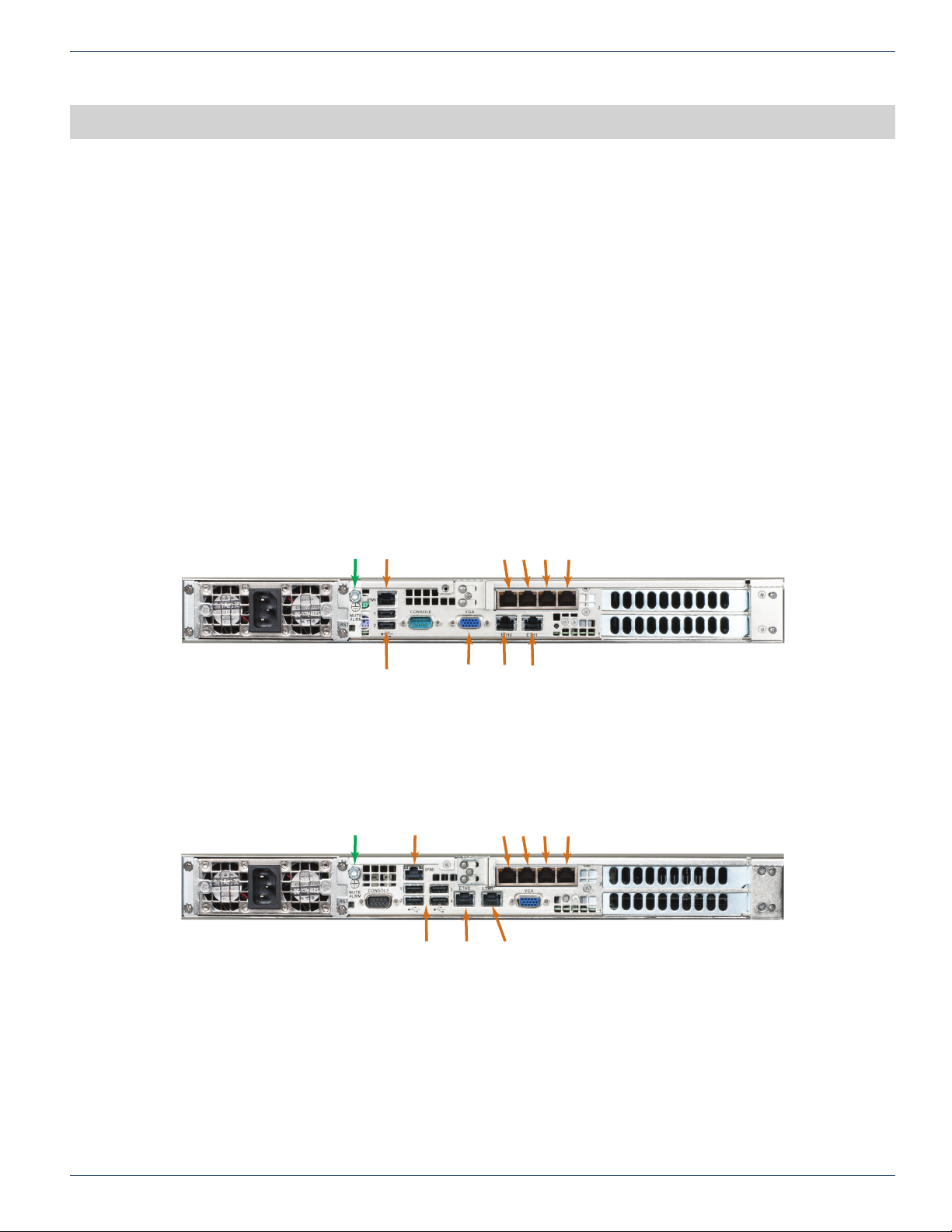
Devices are named by their processing power, Small, Medium and Grande. All Devices are built in two models of chassis
which differ only very slightly by their rear panel layout. The two main rear panel con gurations are illustrated below.
3.1 Chapter Contents
• “Small Chassis Rear Panel”
• “Medium Chassis Rear Panel”
• “Grande Chassis Rear Panel”
• “General Rear Panel Connections”
• “DigiStream Rear Panels”
• “DigiVu® II Rear Panels”
• “VersAtive
3.2 Small Chassis Rear Panel
Devices with 1 or 2 channel capacity and the 4 channel input DigiVu II are built with the Small mainboard with the rear panel
con guration shown in Figure 3-1.
®
Pro Rear Panels”
CHAPTER 3: REAR PANELS
Safety Ground
3.3 Medium Chassis Rear Panel
Devices with 4 channel capacity are built with the Medium mainboard with the rear panel con guration shown in Figure 3-2.
Safety Ground
Figure 3-2: Medium Assembly - Rear Panel
Streaming Ports
VGA
Monitor
eth2 eth3 eth4 eth5
eth0
eth1
MGMT
Streaming
IPMI
USB 1- 2
Figure 3-1: Small Assembly - Rear Panel
Streaming Ports
eth0
MGMT
eth2 eth3 eth4 eth5
eth1
Streaming
IPMI
USB 1- 4
VersAtive®Pro, DigiVu® II, DigiStream – 1RU Hardware Interface Manual 3-1
Page 14
CHAPTER 3: REAR PANELS
192.168.0.23
Streaming Ports
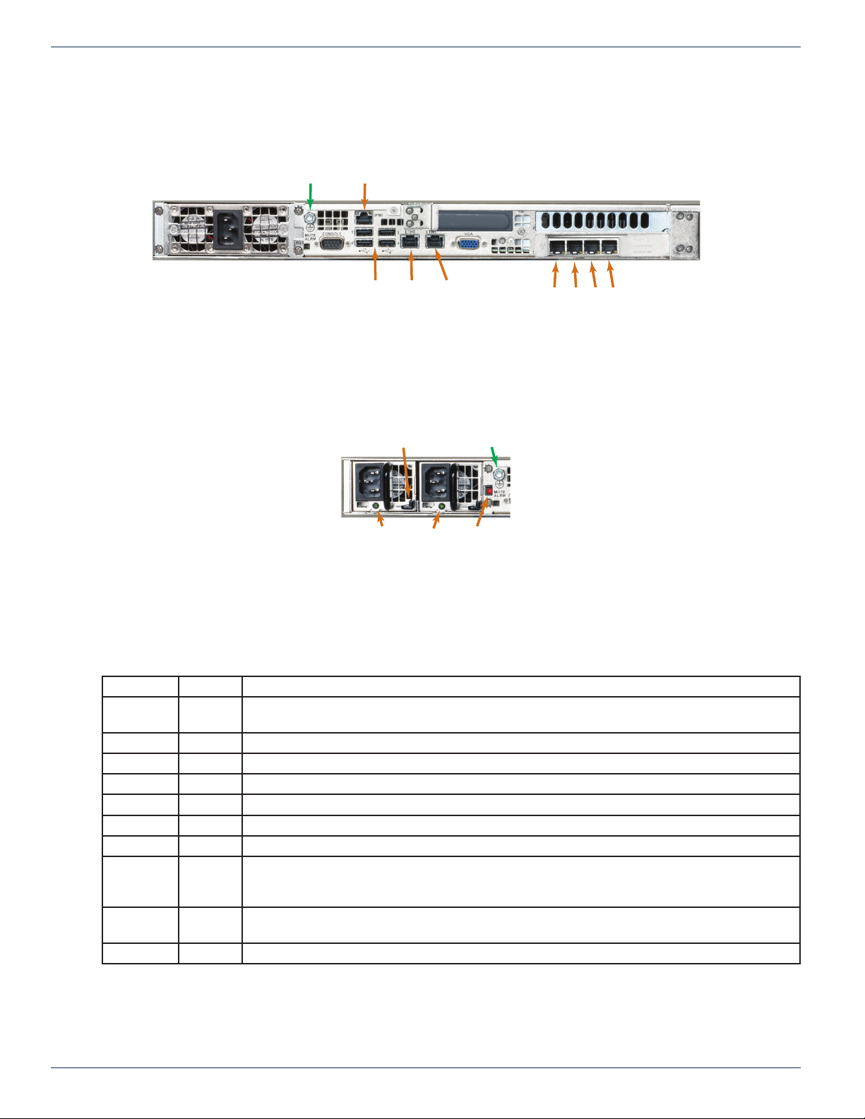
3.4 Grande Chassis Rear Panel
Devices with 6 channel capacity and all VersAtive Pro models are built with the Grande mainboard with the rear panel
con guration shown in Figure 3-2. (VersAtive Pro all have redundant power supplies. Single supply is shown here)
Safety Ground
3.5 Redundant Power Supply
A dual redundant power supply may be ordered as an option in DigiVu II and DigiStream. The redundant power supply is
standard in VersAtive Pro models.
IPMI
eth0
MGMT
eth1
Streaming
USB 1- 4
Figure 3-3: Grande Assembly - Rear Panel
Removal Latch
Power Indicators
Safety Ground
Mute Alarm
Figure 3-4: Redundant Power Supply
eth2eth3eth4eth5
3.6 General Rear Panel Connections
All models have similar rear panel connection functionality, regardless of the size of mainboard, shown in Table 3.6a.
Table 3.6a: Rear Panel Connections - All Models
Port Type Description
eth0 GbE The Management Port is eth0, used to con gure the encoder. Not usually for streaming content.
May also have VLAN virtual ports created.
eth1 GbE Streaming or publishing exclusively for IP based streaming content or VLANs if con gured.
eth2 GbE Streaming or publishing exclusively for IP based streaming content or VLANs if con gured.
eth3 GbE Streaming or publishing exclusively for IP based streaming content or VLANs if con gured.
eth4 GbE Streaming or publishing exclusively for IP based streaming content or VLANs if con gured.
eth5 GbE Streaming or publishing exclusively for IP based streaming content or VLANs if con gured.
IPMI GbE DHCP enabled hardware level interface for encoder management supporting IPMI LAN 2.0.
Mute Alarm Button Used to temporarily disable the audible power supply alarm when one power supply or its power
source have failed. This is present only on dual redundant power supplies (standard on VersAtive
Pro, optional on DigiVu II and DigiStream) shown in Figure 3-4.
VGA DB15HD Used to connect a monitor to access the MKIP system shell. MKIP may also be accessed by SSH
client through eth0 port.
USB USB 2.0 Provided to connect a keyboard and mouse if required to access the MKIP system shell.
3-2 VersAtive®Pro, DigiVu® II, DigiStream – 1RU Hardware Interface Manual
Page 15
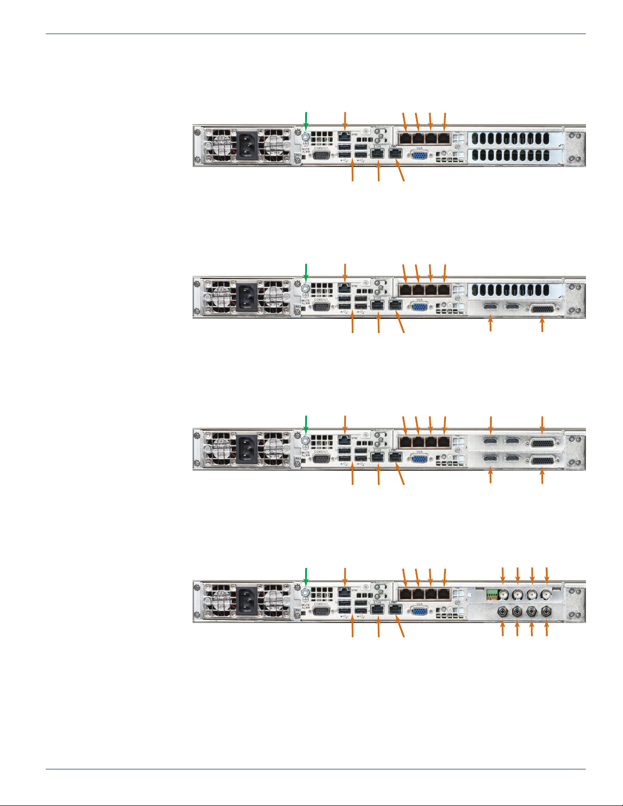
3.7 DigiStream Rear Panels
192.168.0.23
192.168.0.23
192.168.0.23
192.168.0.23
CHAPTER 3: REAR PANELS
DSLI20-00
DSI40-00
No Input Channels
DSLI20-H0
DSI40-H0
1 Input Channel
Input Types:
1 HDMI
1 Component or CVBS
Safety Ground
Safety Ground
Streaming Ports
eth0
MGMT
eth2 eth3 eth4 eth5
eth1
Streaming
IPMI
USB 1- 4
Figure 3-5: DSLI20-00 & DSI40-00
Streaming Ports
eth0
MGMT
eth2 eth3 eth4 eth5
eth1
Streaming
IPMI
USB 1- 4
Figure 3-6: DSLI20-H0 & DSI40-H0
HDMI 1 Component/CVBS 1
(With Adapter Cable)
DSLI20-HH
DSI40-HH
2 Input Channels:
Input Types:
2 HDMI
2 Component or CVBS
DSLI20-S0
DSI40-S0
4 Input Channels:
Input Types:
4 CVBS
Safety Ground
Safety Ground
Streaming Ports
eth0
MGMT
eth2 eth3 eth4 eth5
eth1
Streaming
IPMI
USB 1- 4
Figure 3-7: DSLI20-HH & DSI40-HH
Streaming Ports
eth0
MGMT
eth2 eth3 eth4 eth5
eth1
Streaming
IPMI
USB 1- 4
Figure 3-8: DSLI20-S0 & DSI40-S0
Video
#1
Audio
#1
Video
#2
Audio
#2
Component/CVBS #2
(With Adapter Cable)
(With Adapter Cable)
Video
Video
#4
#3
Audio
Audio
#4
#3
HDMI #2
HDMI #1 Component/CVBS #1
VersAtive®Pro, DigiVu® II, DigiStream – 1RU Hardware Interface Manual 3-3
Page 16
CHAPTER 3: REAR PANELS
192.168.0.23
192.168.0.23
192.168.0.23
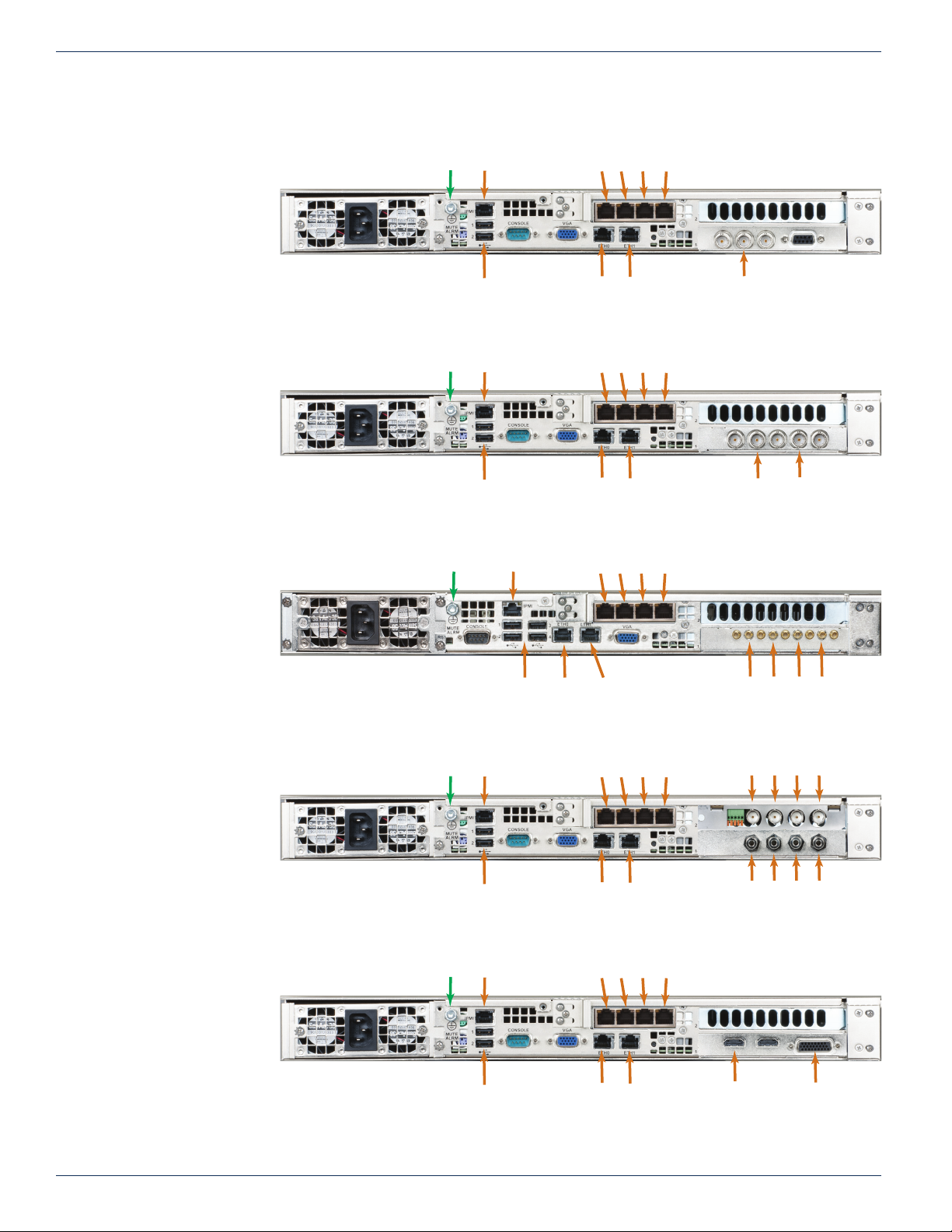
3.8 DigiVu® II Rear Panels
DVT1SDIIP
1 Input Channel
Input Types:
1 SDI
DVT2SDIIP
2 Input Channels
Input Types:
2 SDI
DVT4SDIIP
4 Input Channels
Safety Ground
Safety Ground
Safety Ground
IPMI
USB 1- 2
IPMI
USB 1- 2
Streaming Ports
eth2 eth3 eth4 eth5
eth0
MGMT
Figure 3-9: DVT1SDIIP
Streaming Ports
eth2 eth3 eth4 eth5
eth0
MGMT
192.168.0.23
Figure 3-10: DVT2SDIIP
IPMI
Streaming Ports
eth2 eth3 eth4 eth5
eth1
Streaming
eth1
Streaming
SDI
SDI 1 SDI 2
Input Types:
4 SDI
DVT4SDAIP
4 Input Channels
Input Types:
4 CVBS
DVT1HDMIIP
1 Input Channel
Input Types:
1 HDMI
1 Component or CVBS
Safety Ground
Safety Ground
IPMI
USB 1- 2
IPMI
USB 1- 2
eth0
MGMT
eth1
Streaming
USB 1- 4
Figure 3-11: DVT4SDIIP
Streaming Ports
eth2 eth3 eth4 eth5
eth0
eth1
MGMT
Streaming
192.168.0.23
Figure 3-12: DVT4SDAIP
Streaming Ports
eth2 eth3 eth4 eth5
eth0
eth1
MGMT
Streaming
SDI 1
(Use Adapter Cables)
Video
#1
Audio
#1
HDMI 1
Video
Video
#3
#2
Audio
Audio
Audio
#4
#3
#2
Component/CVBS 1
(with adapter cable)
SDI 4SDI 3SDI 2
Video
#4
Figure 3-13: DVT1HDMIIP
3-4 VersAtive®Pro, DigiVu® II, DigiStream – 1RU Hardware Interface Manual
Page 17
CHAPTER 3: REAR PANELS
192.168.0.23
(Use Adapter Cables)
192.168.0.23
192.168.0.23
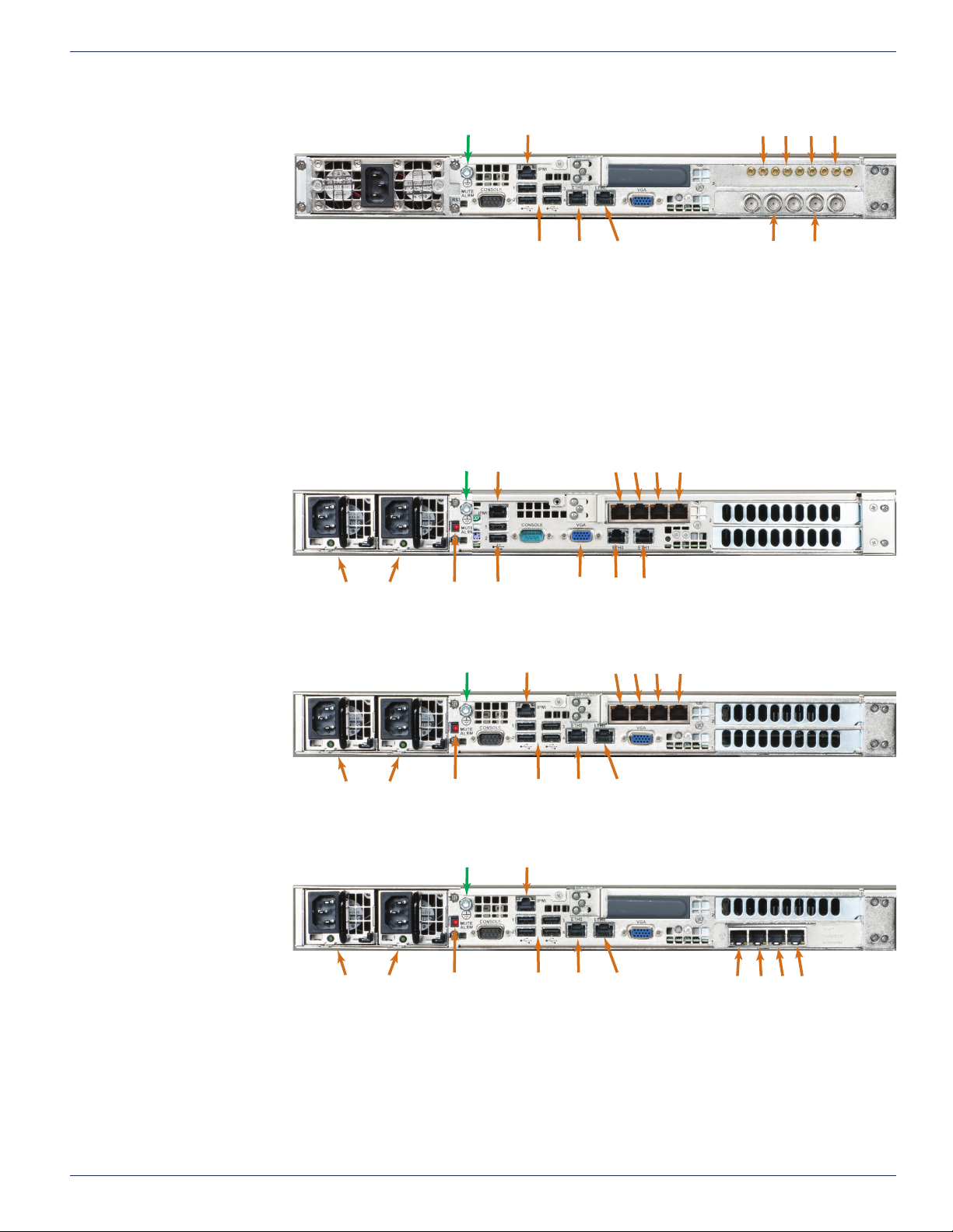
DVT6SDIIP
6 Input Channels:
Input Types:
6 SDI
3.9 VersAtive®Pro Rear Panels
VA-SR
Mainboard: Small
Safety Ground
Safety Ground
IPMI
eth0
USB 1- 4
MGMT
Figure 3-14: DVT6SDIIP
IPMI
eth1
Streaming
Streaming Ports
eth2 eth3 eth4 eth5
SDI 3
SDI 1 SDI 2
SDI 6SDI 5SDI 4
VA-MR
Mainboard: Medium
VA-GR
Mainboard: Grande
Power Indicators Mute Alarm
Safety Ground
Power Indicators Mute Alarm
Safety Ground
Power Indicators
eth0
USB 1- 2
VGA
Monitor
MGMT
192.168.0.23
Figure 3-15: VA-SR Rear Panel
Streaming Ports
eth0
MGMT
eth2 eth3 eth4 eth5
eth1
Streaming
IPMI
USB 1- 4
Figure 3-16: VA-MR Rear Panel
IPMI
USB 1- 4
eth0
eth1
MGMT
Streaming
Figure 3-17: VA-GR Rear Panel
eth1
Streaming
Streaming Ports
eth2eth3eth4eth5Mute Alarm
VersAtive®Pro, DigiVu® II, DigiStream – 1RU Hardware Interface Manual 3-5
Page 18

CHAPTER 3: REAR PANELS
This page intentionally left blank.
3-6 VersAtive®Pro, DigiVu® II, DigiStream – 1RU Hardware Interface Manual
Page 19

INSTALLATION
4. Installation
This chapter provides a guide to get your Device up and running. Following these steps should enable you to have the system
operational within a minimum amount of time.
4.1 Chapter Contents
• “Preparation for Installation”
• “Precautions”
• “General Mechanical”
• “Gigabit Ethernet Ports”
• “Install the Chassis in a Rack”
• “Equipment Safety Grounding”
• “Power Supplies”
• “Ethernet Cabling”
CHAPTER 4: INSTALLATION
4.2 Preparation for Installation
Carefully unpack the equipment from the shipping box. If the box or equipment is damaged, notify the freight company to make
a damage claim. If you suspect that there is a problem with the equipment that may preclude safe operation, do not install or
operate it. Contact ATX Networks immediately for instructions.
NOTE: This equipment is intended for installation in a RESTRICTED ACCESS LOCATION only.
NOTE: This equipment is NOT for use in a computer room as defi ned in the Standard for Protection
of Electronic Computer/Data Processing Equipment, ANSI/NFPA 75.
NOTE: This equipment is intended for use in a fi xed position and should be installed securely
before operation is initiated.
4.3 Precautions
4.3.1 Electrical Precautions
Basic electrical safety precautions should be followed to protect yourself from harm and the Device chassis from damage:
• Be aware of the locations of the power on/off switch on the chassis as well as the room’s emergency power-off switch,
disconnection switch or electrical outlet. If an electrical accident occurs, you can then quickly remove power from the
system.
• Power should always be disconnected from the system when servicing. When disconnecting power, you should rst
power down the operating system rst and then unplug the power cords. The unit has more than one power supply
cord. Disconnect two power supply cords before servicing to avoid electrical shock.
• When working around exposed electrical circuits, another person who is familiar with the power-off controls should
be nearby to switch off the power if necessary.
• Use only one hand when working with powered-on electrical equipment. This is to avoid making a complete circuit,
which will cause electrical shock. Use extreme caution when using metal tools, which can easily damage any electrical
components or circuit boards they come into contact with.
• Do not use mats designed to decrease static electrical discharge as protection from electrical shock. Instead, use
rubber mats that have been speci cally designed as electrical insulators.
• The power supply power cords must include a grounding pin and must be plugged into grounded electrical outlets.
• Remove any jewelry or metal objects from your body, which are excellent metal conductors that can create short
VersAtive®Pro, DigiVu® II, DigiStream – 1RU Hardware Interface Manual 4-1
Page 20

CHAPTER 4: INSTALLATION
circuits and harm you if they come into contact with printed circuit boards or areas where power is present.
• This product may be connected to an IT power system. In all cases, make sure that the unit is also reliably connected
to Earth (ground).
4.3.2 General Precautions
• The Devices weighs approximately 25 lbs (11.3kg) when fully loaded. When lifting the system, two people should lift
slowly with their feet spread out to distribute the weight. Always keep your back straight and lift with your legs.
• While working on the system, do not wear loose clothing such as neckties and unbuttoned shirt sleeves, which can
come into contact with electrical circuits or be pulled into a cooling fan.
• After accessing the inside of the Device, close the chassis back up and secure it to the rack unit with the retention
screws and ensure that all connections have been made.
4.3.3 Chassis Precautions
• Determine the placement of each component in the rack before you install the rails.
• Install the heaviest components on the bottom of the rack rst, and then work up.
• Use a regulating uninterruptible power supply (UPS) to protect the Device from power surges, voltage spikes and to
keep your system operating in case of a power failure.
• Allow any power supply modules to cool before touching them.
4.3.4 Rack Precautions
• Ensure that the leveling jacks on the bottom of the rack are fully extended to the oor with the full weight of the rack
resting on them.
• In single rack installation, stabilizers should be attached to the rack. In multiple rack installations, the racks should
be coupled together.
4.4 General Mechanical
• The equipment will require 1RU of vertical rack space and may be mounted directly above or below other equipment
without providing space between, however, 1RU space should be maintained from other equipment which generates
signicant heat. Leave enough clearance in front of the rack to enable you to work on the chassis (~25 inches) and
approximately 30 inches of clearance in the back of the rack to allow for sufcient airow and ease of servicing.
• Be sure to maintain freedom of air movement around equipment. Installation of the equipment in enclosed racks
is not recommended due restricted air ow. The equipment is designed to operate to specication in an ambient
temperature of +10°C to +35°C (+50°F to +95°F). Normal room temperature is recommended to ensure proper long
term operation of the equipment.
• Consideration should be given to the connection of the equipment to the mains power and the effect that any possible
overloading of circuits might have on over current protection and wiring.
• Rear support of the unit is mandatory and rails for attachment to rear supports are provided. Do not use the unit
chassis to support other equipment. Alternately, if rear support rails are unavailable or impractical, install the unit on
a well supported shelf.
4.5 Gigabit Ethernet Ports
The input ports eth1, eth2, eth3, eth4, eth5 are auto-negotiating and intended to be connected to a network distribution switch
using straight through wired Cat5e or better quality cable. The rear panel Management Interface port allows connection to a
notebook or desktop PC for managing and conguring the system. The port may be connected to directly, or in the case of
a headend with many devices to manage, may be connected to a management network (recommended) or the distribution
switch containing the video stream content. It is possible to set up virtual ports for a VLAN. Connections should be made with
Cat5e or better network cables. The GigE management port is auto-negotiating and should be connected to a switch or router
with a straight through wired cable. Direct connection to a PC may be made with the supplied crossover cable.
4-2 VersAtive®Pro, DigiVu® II, DigiStream – 1RU Hardware Interface Manual
Page 21
4.6 Install the Chassis in a Rack
This section provides information on installing the Device chassis in a rack unit with the rails provided. There are a variety of
rack units on the market, which may mean that the assembly procedure will differ slightly from the instructions provided. You
should also refer to the installation instructions or adapt these instructions to suit the rack unit you are using.
NOTE: The illustrations in Figure 4-4 and Figure 4-5 are for general guidance purposes only.
Always install the Device chassis to the bottom of the rack fi rst to avoid the rack becoming top
heavy.
4.6.1 Identifying the Rack Rail Sections
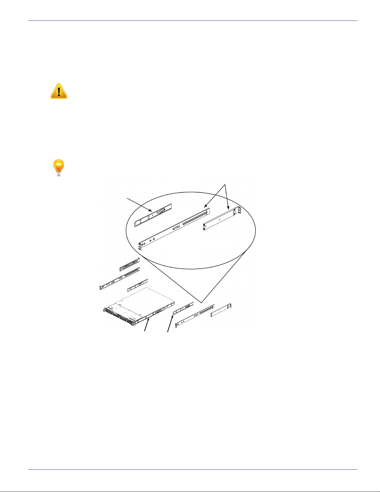
The Device chassis includes two rail assemblies in the rack mounting kit. Each assembly consists of two sections: An inner
chassis rail secured to the chassis (front part is factory installed, extension is eld installed), an outer rail that secures to the
rack, and an outer rail extension that secures directly to the rear vertical support, Figure 4-1. Each of these assemblies are
designed for mounting universally on the left or right side of the chassis.
NOTE: This rail will fi t a rack between 26” and 33.5” deep.
CHAPTER 4: INSTALLATION
(Inner rail is factory-assembled
on the chassis)
Inner rail factory installed
Figure 4-1: Identifying Rack Rail Sections
Outer RailsInner Rail Extension
Inner Rail extension
VersAtive®Pro, DigiVu® II, DigiStream – 1RU Hardware Interface Manual 4-3
Page 22
CHAPTER 4: INSTALLATION
2
3
4.6.2 Install Inner Rail Extensions
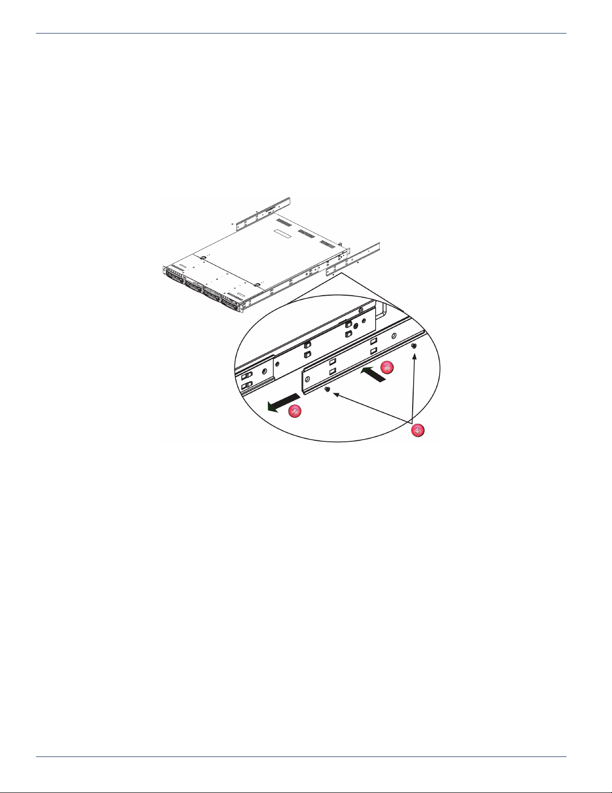
The chassis includes a set of inner rails which are in two sections: inner rails and inner rail extensions. The inner rails are
pre-attached and do not interfere with normal use of the chassis if you decide not to use a server rack. Attach the inner rail
extension to help support the rear of the chassis within the rack.
1. Place the inner rail extensions on the side of the chassis aligning the hooks of the chassis with the inner rail extension
holes, Figure 4-2. Make sure the inner rail extension faces “outward” just like the pre-attached inner rail.
2. Slide the extension toward the front of the chassis latching it onto the hooks.
3. Secure the rail extension with 2 screws as illustrated.
4. Repeat steps 1-3 for the other inner rail extension
Figure 4-2: Identifying Rack Rail Sections
1
4-4 VersAtive®Pro, DigiVu® II, DigiStream – 1RU Hardware Interface Manual
Page 23
4.6.3 Install the Outer Rails in the Rack
1
2
3
4
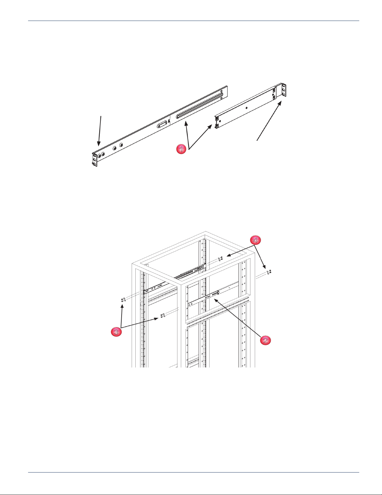
1. Attach the longer section of the outer rail to the outside of the shorter section of the outer rail, Figure 4-3. You must
align the pins with the slides. Both ends of the outer rail must face the same direction in order to be secured to the
rack.
Secure to rack front rails
Attach the 2 sections tegether
CHAPTER 4: INSTALLATION
Secure to the rear rack support rails
Figure 4-3: Install Rail Sections
2. Adjust both sections of the outer rail to the proper length so that the rail ts snugly within the rack, Figure 4-4.
3. Secure the longer section of the outer rail to the of the front rack rails with two 10-32 rack screws.
4. Secure the shorter section to the rear rack rails with two 10-32 rack screws.
5. Repeat steps 1-4 for the remaining outer rail.
Figure 4-4: Install Outer Rails to Rack
VersAtive®Pro, DigiVu® II, DigiStream – 1RU Hardware Interface Manual 4-5
Page 24
CHAPTER 4: INSTALLATION
Inner rails
Inner Rail
extensions
Outer rails and extensions
1
2
3
1
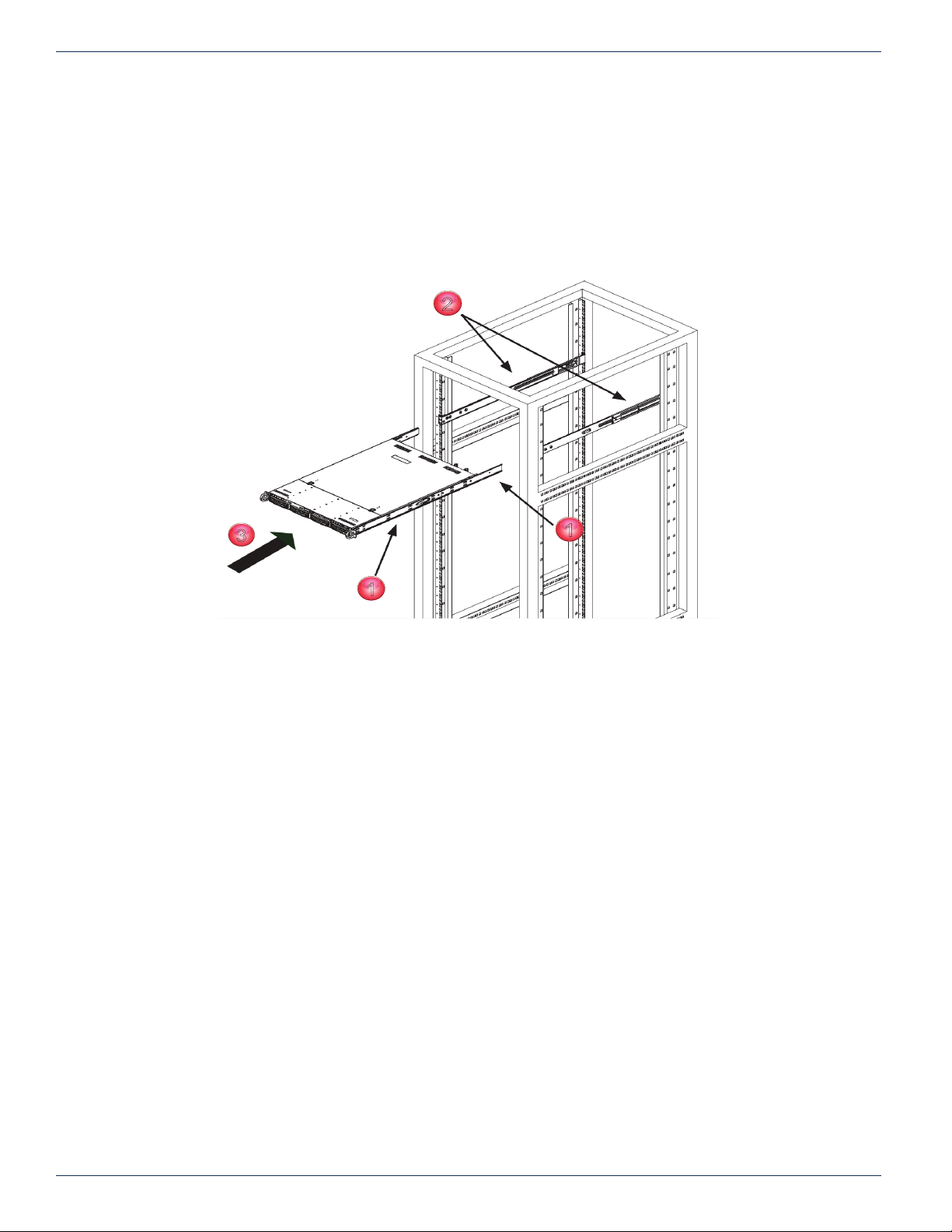
4.6.4 Mount the Chassis
1. Con rm that the inner rails and rail extensions have been installed on the chassis.
2. Con rm that the outer rails and extensions are installed on the rack.
3. Line up the chassis rails with the front of the outer rack rails, then slide the chassis rails into the rack rails, keeping the
pressure even on both sides (you may have to depress the locking tabs when inserting). When the Device has been
pushed completely into the rack, you should hear the locking tabs “click” into the locked position.
4. Insert and tighten the screws that hold the front of the Device to the rack if desired.
Figure 4-5: Install Chassis to Rack
4-6 VersAtive®Pro, DigiVu® II, DigiStream – 1RU Hardware Interface Manual
Page 25
4.7 Equipment Safety Grounding
Reliable earthing of rack-mounted equipment should be maintained. Particular attention should be given to supply connections
other than direct connections to the branch circuit (e.g. use of power strips). The following guidelines are provided to clarify
the requirements for the installation to meet UL, CUL and CB standards. The use of the words “Ground” and “Earth” as well as
“Grounding” and “Earthing” may be used interchangeably and in this context, have the same meaning.
NOTE: It is imperative that the encoder chassis be connected to a permanent building ground to
comply with UL, CUL and CB standards.
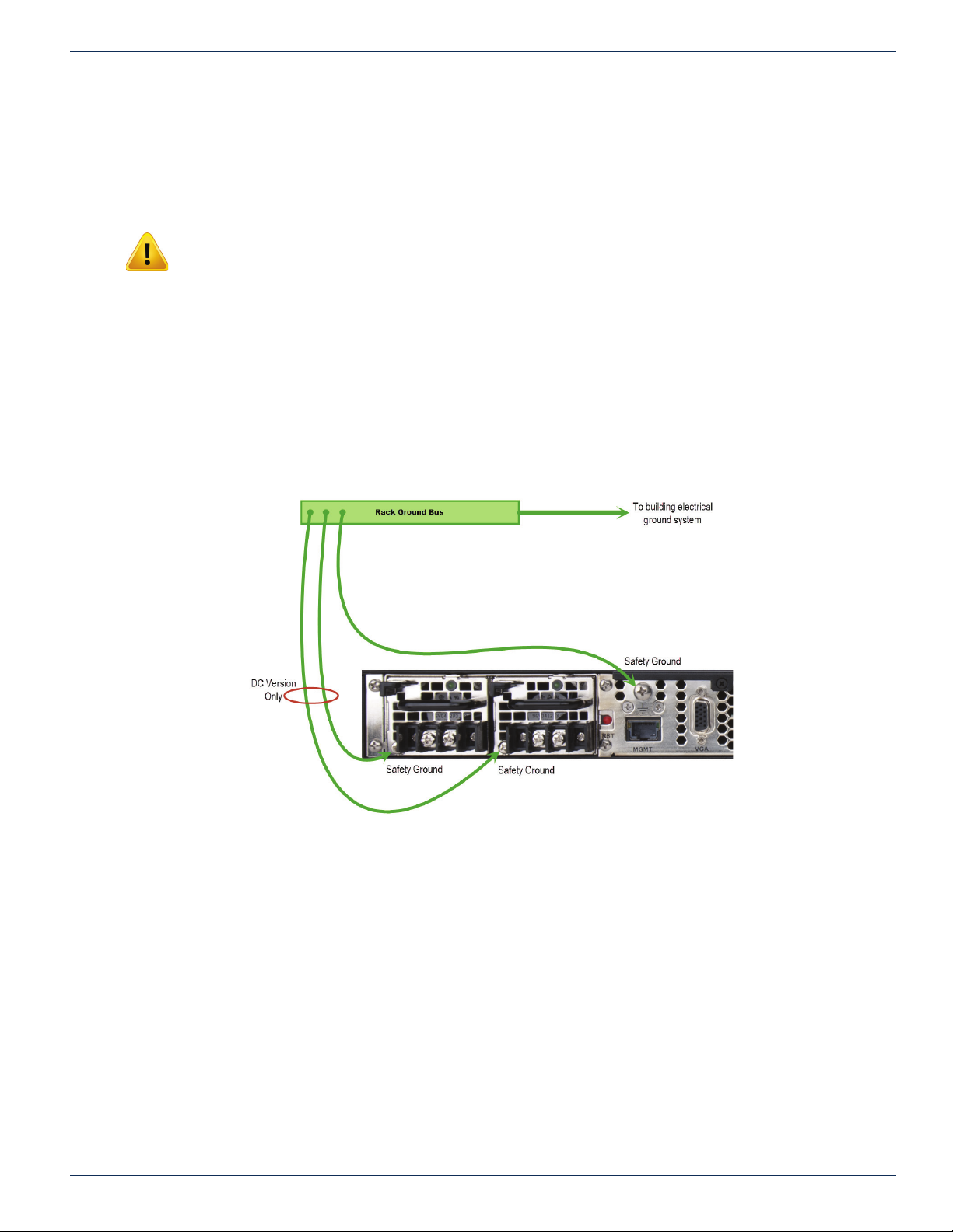
It is important that the Device housing and power supplies be connected to a permanent building ground in a manner that
will ensure that the exposed metal parts are constantly connected to ground through independent means even when the
power supply cord or wires may be disconnected temporarily. Ground connections screws are provided on the rear panel to
conveniently effect such a connection, Figure 4-6.
4.7.1 Ground Connection to Earth
The supplementary equipment grounding conductor is to be installed between the rear panel ground screws and earth, that
is, in addition to the equipment ground conductor in the power supply cord or wires. The screw terminals provided for this
connection are located on the rear panel adjacent to the power supplies and one each on the DC power supply modules (if
equipped) as shown in Figure 4-6.
CHAPTER 4: INSTALLATION
Figure 4-6: Recommended Equipment Safety Ground Connections
4.7.2 Ground Conductor Size
The supplementary equipment grounding conductor may not be smaller in size than the branch-circuit supply conductors
or a minimum #14 AWG. The supplementary equipment grounding conductor is to be connected at the rear panel terminal
provided, and connected to earth in a manner that will retain the earth connection when the power supply cord is unplugged.
The connection to earth of the supplementary grounding conductor shall be in compliance with the appropriate rules for
terminating bonding jumpers in Part V of Article 250 of the National Electrical Code, ANSI/NFPA 70, and Section 10 of Part I
of the Canadian Electrical Code, Part I, CSA C22.1.
4.7.3 Ground Conductor Termination
Termination of the supplementary equipment grounding conductor may be made to building steel, to a metal electrical raceway
system, or to any grounded item that is permanently and reliably connected to the electrical service equipment earth.
4.7.4 Ground Conductor Type
Bare, covered or insulated grounding conductors are acceptable. A covered or insulated grounding conductor shall have a
continuous outer nish that is either green, or green with one or more yellow stripes.
VersAtive®Pro, DigiVu® II, DigiStream – 1RU Hardware Interface Manual 4-7
Page 26
CHAPTER 4: INSTALLATION
Safety Ground
Safety Ground
4.8 Power Supplies
Power supplies for AC and DC operation are available as options and each may be ordered in a redundant supply version.
The following points must be taken into account when installing the Device and connecting power.
4.8.1 AC Power Supplies
Both the standard single power supply and the optional redundant AC power supplies are auto-sensing switching type power
supply systems which may be operated on input voltages from 115 VAC to 230 VAC. There is no need to con gure the power
supplies to operate on any voltage in this range. Power cords appropriate to the locale are supplied.
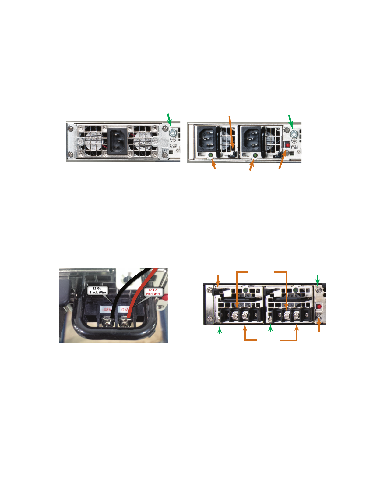
Figure 4-7: Single AC Power Supply
4.8.2 DC Power Supply and Termination
The optional redundant DC switching type power supply system is intended to operate on nominal -48 VDC power systems
but functions between -40 and -72 VDC. A pair of insulated #12 AWG DC power wires must be eld installed for each of the
two modules using permanent wiring methods. Wire insulation colors must be different for each of the two conductors clearly
indicating the polarity of the voltage, see Figure 4-9. It is recommended that stranded conductors be used for DC power and
that RED wire be used for the 0V conductor and BLACK for the -48V conductor. Ring or spade terminals may be used and it
is also permissible to strip the wire 8mm, twist the stranded conductors tightly and clamp the wire in the provided wire clamp
as illustrated in Figure 4-9.
Removal Latch
Power Indicators
Figure 4-8: Redundant AC Power Supply
Safety Ground
Mute Alarm
-48Volts InLatch
Figure 4-9: DC Power Module Connections
Gnd Gnd
0Volts In
Figure 4-10: Redundant DC Power Supply
Mute
Alarm
4.8.3 DC Power Disconnect
Each DC power module should be externally fused or otherwise adequately protected at no more that 10 Amperes and
must be provided with it’s own external readily accessible disconnect device. Each disconnect must be prominently labeled
indicating the units being powered and with adequate instructions for the removal of all power from the unit being serviced.
The disconnect must be turned off for BOTH power modules before removing supply wires from the module terminal blocks
when replacing a power supply module or otherwise servicing the unit.
4.8.4 Power Supply Redundancy
For the redundant power supply options, either power module on its own can provide the required power safely if one fails. To
retain the redundancy feature, replace a failed power module as soon as possible. A power module failure or the failure of the
supply current or protection fuse will be indicated by an audible alarm within the encoder power modules and the green power
status LED on the power module will be extinguished. Silence the audible alarm with the red rear panel Alarm Reset switch
adjacent to the power supply modules, Figure 4-10.
4-8 VersAtive®Pro, DigiVu® II, DigiStream – 1RU Hardware Interface Manual
Page 27

4.8.5 Redundant Power Module Replacement
AC Version
NOTE: The power cords for BOTH power modules must be disconnected before attempting to
remove the power modules or otherwise servicing the unit.
Power module failure will be indicated by the alarm being sounded and the green status light on the module will no longer be
lit. This power module may be replaced by rst disconnecting the AC power cord from the IEC input socket of BOTH power
modules, then release the module by pressing down on the thumb latch at the top of each module. Extract the module and
replace with an identical replacement module only.
DC Version
NOTE: The external disconnect for BOTH power modules must be turned off before attempting
to disconnect the DC wiring from the power module terminals or otherwise servicing the unit.
Power module failure will be indicated by the alarm being sounded and the green status light on the module will no longer be
lit. This power module may be replaced by rst disconnecting the DC power at the external disconnect device for BOTH power
modules then use a Phillips screw driver to remove the DC wires from the failed module terminals. Release the module by
pressing down on the thumb latch at the top of each module and extract the module. Replace with an identical replacement
module only.
CHAPTER 4: INSTALLATION
4.8.6 Power Cord Protection
Measures must be taken during installation to route or arrange the power supply cords or wires to prevent physical damage
and to avoid the possibility of future damage occurring. The cords shall be installed and routed such that, throughout it’s
length, the cord and it’s points of connection are not strained in any way.
4.8.7 Power Cord Attachment
The unit AC power supply cords shall not be attached to a building surface, bundled with audio, video or RF coaxial cables,
nor run through walls, ceilings, oors and similar openings in the building structure.
4.8.8 Provision of Electrical Power Outlet
An AC electrical power outlet of appropriate type and rating shall be provided near the location where the unit is installed
and easily accessible such that the provided power supply cords may be routed in an appropriate manner, without the use of
extension cords, between the receptacle and the chassis. Alternately, the chassis shall be installed in close proximity to an
existing AC electrical outlet such that the requirements of this paragraph are achieved.
4.8.9 IEC Power Input Cord for AC
The AC power input receptacle is a standard IEC C13 connector similar to that commonly used on computers and monitors.
The power cords provided with the product is a North American con guration with a NEMA 5-15 grounded plug for 115 VAC.
If it is necessary to operate the product on 230 VAC, the installer must obtain IEC cords with a NEMA 6-15 grounded plug for
use in North America. This may be obtained at time of order from ATX Networks or locally. If shipped outside of North America,
the encoder will be supplied with an IEC cord set appropriate for the locale to which it is shipped.
4.8.10 Input Power Requirements
When installing the equipment, it is the responsibility of the installer to determine that suf cient capacity is available in the
electrical circuit feeding the unit to avoid overloading the supply circuit. The AC model will require power to be supplied from a
properly grounded AC outlet. The installer shall determine that the AC power outlet, its wiring and receptacle is in compliance
with local and/or national electrical codes as applicable. The AC input power requirement is constant over the range of input
voltages. At higher input voltages, the current consumption is lower than it is at lower voltages where the input current is higher.
4.8.11 Fusing
Internal over-current protection is built in to the power modules. There is no internal fuse to be replaced or maintained on either
the AC or DC versions. Each DC power supply, if installed, should be externally fused at no more that 10 Amperes.
VersAtive®Pro, DigiVu® II, DigiStream – 1RU Hardware Interface Manual 4-9
Page 28

CHAPTER 4: INSTALLATION
4.9 Ethernet Cabling
4.9.1 Management Port (eth0)
The rear panel Management Interface port allows connection to a notebook or desktop PC for managing and conguring the
system. The port may be connected to directly, or in the case of a headend with many devices to manage, may be connected
to a management network (recommended) or the distribution switch containing the video stream content. Connections should
be made with Cat5e or better network cables. The 10/100 Base-T management ports is DTE and should be connected to a
switch or router with a straight through wired cable. Direct connection to a PC should be made with the supplied crossover
cable.
4.9.2 Ethernet Streaming Ports (eth1, eth2, eth3, eth4, eth5)
The ports are auto-negotiating and intended to be connected to a network distribution switch using straight through wired
Cat5e or better quality cable. The 10/100/1000 Base-T ports negotiate an appropriate connection speed dependant on the
type of external port it is connected to.
4-10 VersAtive®Pro, DigiVu® II, DigiStream – 1RU Hardware Interface Manual
Page 29
STARTUP
5. Startup
Each of the Device chassis are factory con gured identically with the standard ATX Networks default IP address of 192.168.0.23
assigned to port eth0 (Management Port). Before connecting each Device to the management switch, the IP addresses must
be re-con gured for your network.
NOTE: This equipment must have default eth0 port IP addresses changed from 192.168.0.23
before operation is initiated.
NOTE: It is important to connect the eth1, eth2, eth3, eth4 & eth5 streaming ports to a GbE
capable switch or risk uncontrolled continuity errors as a connected 100 Base-T network may be
ooded.
5.1 Chapter Contents
• “Management Computer”
• “Connecting to Your Computer”
CHAPTER 5: STARTUP
5.2 Management Computer
It is required that the Management Computer meet these minimum requirements.
• Wired Ethernet network port.
• Web browser for Management GUI on 192.168.0.23.
5.3 Connecting to Your Computer
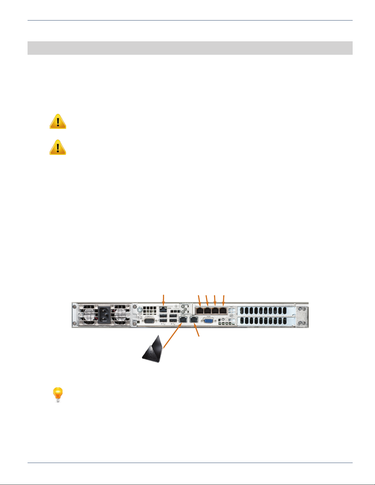
All Device rear panels have eth0 Management ports factory assigned IP address 192.168.0.23, Figure 5-1.
Figure 5-1: Rear Panel Management Port - 192.168.0.23
NOTE: Please refer to the Operation Manual for programming guidance.
IPMI
eth0
MGMT
192.168.0.23
Streaming Ports
eth2 eth3 eth4 eth5
eth1
Streaming
VersAtive®Pro, DigiVu® II, DigiStream – 1RU Hardware Interface Manual 5-1
Page 30

CHAPTER 5: STARTUP
This page intentionally left blank.
5-2 VersAtive®Pro, DigiVu® II, DigiStream – 1RU Hardware Interface Manual
Page 31

SAFETY
6. Safety
WARNING! FAILURE TO FOLLOW THE SAFETY PRECAUTIONS LISTED BELOW MAY RESULT IN PROPERTY DAMAGE
OR PERSONAL INJURY. PLEASE READ AND COMPLY WITH THE FOLLOWING:
SAFETY GROUND: The connection to earth of the supplementary grounding conductor, if provided, shall be in compliance
with the appropriate rules for terminating bonding jumpers in Part V of Article 250 of the National Electrical Code, ANSI/NFPA
70, and Section 10 of Part I of the Canadian Electrical Code, Part I, CSA C22.1.
GROUNDING OR POLARIZATION: Electrical cord grounding and polarization means must not be defeated.
WATER AND MOISTURE: Care should be taken to prevent entry of splashed or dripping water, other liquids, and physical
objects through enclosure openings.
DAMAGE: Do not operate the device if damage to any components is suspected.
POWER SOURCES: Only connect the unit to a power supply of the type and capacity specied in the operating instructions
or as marked on the device.
CHAPTER 6: SAFETY
NOTE: a) For 115 VAC operation, use the power cord supplied for operation from a 115 VAC source.
b) For 230 VAC operation, use the power cord supplied for operation from a 230 VAC source.
c) For DC operation, use insulated power leads of #12 AWG stranded wire for operation on -40 to -72 VDC
POWER CORD PROTECTION: Power supply cords should be routed so that they are not likely to be pinched by items
placed upon or against them, paying particular attention to cords at plugs, convenience receptacles, and the point where they
exit from the device.
SERVICE: Do not attempt to service the device beyond procedures provided in the operating instructions. All other servicing
should be referred to qualied service personnel.
MODIFICATIONS: Modications should not be made to the device or any of its components for applications other than those
specied in the operating instructions.
SAFETY CODES AND REGULATIONS: The device should be installed and operated in compliance with all applicable local
safety by-laws, codes and regulations.
REDUNDANT POWER SUPPLY REMOVAL: Power must be disconnected from the BOTH power modules before removing
for replacement or service. This is accomplished by removing both of the AC IEC plugs or operating the DC power disconnects.
VersAtive®Pro, DigiVu® II, DigiStream – 1RU Hardware Interface Manual 6-1
Page 32

CHAPTER 6: SAFETY
This page intentionally left blank.
6-2 VersAtive®Pro, DigiVu® II, DigiStream – 1RU Hardware Interface Manual
Page 33

SERVICE & SUPPORT
7. Service & Support
7.1 Contact ATX Networks
Please contact ATX Technical Support for assistance with any ATX products. Please contact ATX Customer Service to obtain
a valid RMA number for any ATX products that require service and are in or out-of-warranty before returning a failed module
to the factory.
DIGITAL VIDEO SUPPORT LINE
Tel: (905) 428-6068
Toll Free: (800) 565-7488 (USA & Canada only)
► Press
►Then press 1 for Digital Video Products
Email: [email protected]
CUSTOMER SERVICE
ATX Networks
1-501 Clements Road West
Ajax, ON L1S 7H4 Canada
3 for Technical Support
*
CHAPTER 7: SERVICE & SUPPORT
Tel: (905) 428-6068
Toll Free: (800) 565-7488 (USA & Canada only)
► Press *1 for Customer Service
Fax: (905) 427-1964
Toll Free Fax: (866) 427-1964 (USA & Canada only)
Web: www.atxnetworks.com
Email: [email protected]
7.2 Warranty Information
All of ATX Networks’ products have a 1-year warranty that covers manufacturer’s defects or failures.
VersAtive®Pro, DigiVu® II, DigiStream – 1RU Hardware Interface Manual 7-1
Page 34

ISO
REGISTERED
9001:15
End-of-Sale as of
March 31, 2017
© 2018 ATX Networks
Information in this document is subject to change without notice.
Rev. 08/18 (ANW1080)
ATX Networks
1-501 Clements Road West, Ajax, ON L1S 7H4 Canada
Tel: 905.428.6068 | Toll Free: 800.565.7488 | [email protected]
www.atxnetworks.com
 Loading...