

Page 1

ChromaFlex
ChromaFlex DMT24, DMT34 & DMT44 Multi-Wavelength
DWDM Direct Modulated Transmitter Module
HARDWARE INTERFACE MANUAL
www.atxnetworks.com
www.atxnetworks.com
Page 2

Although every effort has been taken to ensure the accuracy of this document it may be necessary, without notice, to make amendments or correct omissions.
Specications subject to change without notice.
Products or features contained herein may be covered by one or more U.S. or foreign patents. DOCSIS® and other non-ATX product and company names in this manual are the property of their
respective companies.
Page 3

TABLE OF CONTENTS
1 IMPORTANT SAFETY INSTRUCTIONS .................................... 1-1
1.1 Electric Shock Hazard ............................................. 1-1
1.2 Installation Site ................................................... 1-1
1.3 Installation Requirements ........................................... 1-1
1.4 Equipment Placement. . . . . . . . . . . . . . . . . . . . . . . . . . . . . . . . . . . . . . . . . . . . . . 1-1
1.5 Power Connections. . . . . . . . . . . . . . . . . . . . . . . . . . . . . . . . . . . . . . . . . . . . . . . . 1-2
1.5.1 Connection To AC Power Source .................................... 1-2
1.5.2 Connection To -48 VDC Power Source ................................ 1-2
1.6 Fuse Replacement ................................................ 1-2
1.7 Laser Safety ..................................................... 1-2
1.8 Laser Power & Warning Labels ...................................... 1-3
2 PRODUCT INTRODUCTION ............................................. 2-1
3 UNPACKING & INSPECTING A NEW UNIT ................................. 3-1
3.1 What To Do About Physical Damage .................................. 3-1
3.2 What To Do About Concealed Damage ................................ 3-1
3.3 How To Return Equipment .......................................... 3-1
4 SPECIFICATIONS ...................................................... 4-1
5 BLOCK DIAGRAM & OPERATION ........................................ 5-1
6 FRONT PANEL ........................................................ 6-1
6.1 Front Panel Illustration ............................................. 6-1
6.2 Table of Front Panel Features ....................................... 6-1
6.3 Alarm Status Indicators ............................................. 6-1
7 MODULE INSTALLATION ............................................... 7-1
8 MODULE CONNECTIONS ............................................... 8-1
8.1 RF Connections .................................................. 8-1
8.2 Optical Connections ............................................... 8-2
9 MODULE SET-UP ...................................................... 9-1
9.1 Setting RF Input Levels ............................................ 9-1
9.1.1 All QAM Channels ................................................ 9-1
9.1.2 Mix of Analog & QAM Channels ..................................... 9-1
9.2 Conguring The DMTx4 Transmitter Module ............................ 9-1
9.2.1 AGC Mode (Hand-held Display) ...................................... 9-2
9.2.2 MGC Mode (Hand-held Display) ...................................... 9-3
9.3 Setting Transmitter Fiber Length ..................................... 9-4
10 TROUBLESHOOTING THE DMTX4 ....................................... 10-1
11. SERVICE & SUPPORT ................................................. 11-1
11.1 Contact ATX Networks .............................................11-1
11.2 Warranty Information ..............................................11-1
ChromaFlex DMT24, DMT34 & DMT44 Multi-Wavelength DWDM Direct Modulated Transmitter Module – Hardware Interface Manual iii
Page 4

This page intentionally left blank.
iv ChromaFlex DMT24, DMT34 & DMT44 Multi-Wavelength DWDM Direct Modulated Transmitter Module – Hardware Interface Manual
Page 5

IMPORTANT SAFETY INSTRUCTIONS
1. Important Safety Instructions
• Carefully read all safety and operating instructions contained in this user guide before operating this equipment, and
retain them for future reference.
• Follow all installation and operating instructions. Pay attention to all warnings and cautions in the manual as well as
those that are af xed to this equipment.
1.1 Electric Shock Hazard
This equipment meets applicable safety standards.
WARNING: To reduce risk of electric shock, perform only the instructions that are included in the
operating instructions. Refer all servicing to qualifi ed service personnel only.
Adhere to the following safety warnings and guidelines:
• Dangerous Voltages
◦ Only quali ed service personnel are allowed to perform equipment installation or replacement.
◦ Disconnect power before servicing the unit.
◦ Only quali ed service personnel are allowed to remove chassis covers and access only eld replaceable
pluggable accessories.
• Grounding
◦ Do not violate the protective grounding by using extension cables, power cables, or other devices on
the mains power without a protective ground conductor.
◦ If this equipment is equipped with an external grounding terminal, attach one end of an 18-gauge
wire (or larger) to the grounding terminal; then, attach the other end of the wire to a ground, such as a
grounded equipment rack.
CHAPTER 1:
IMPORTANT SAFETY INSTRUCTIONS
1.2 Installation Site
When selecting the installation site, comply with the following:
• Maintain a Protective Ground - The protective ground lead of the building’s electrical installation should comply with
national and local electrical and safety requirements.
• Environmental Condition - The installation site should be dry, clean, and ventilated. Do not use this equipment where
it could be at risk of contact with water. Ensure that this equipment is operated in an environment that meets the
requirements as stated in this equipment’s environmental speci cations.
1.3 Installation Requirements
WARNING: Allow only qualifi ed service personnel to install this equipment. The installation must
conform to all local codes and regulations.
1.4 Equipment Placement
WARNING: Avoid personal injury and damage to this equipment. An unstable mounting surface
may cause this equipment to fall.
• Install this equipment in a restricted access location.
• Place this equipment close enough to a mains AC outlet to accommodate the length of this equipment’s power cord.
• Route all power cords so that people cannot walk on, place objects on, or lean objects against them.
• Make sure the mounting surface or rack is stable and can support the size and weight of this equipment.
ChromaFlex DMT24, DMT34 & DMT44 Multi-Wavelength DWDM Direct Modulated Transmitter Module – Hardware Interface Manual 1-1
Page 6

CHAPTER 1:
IMPORTANT SAFETY INSTRUCTIONS
• Make sure that the rack is placed on a stable surface. If the rack has stabilizing devices, install these stabilizing
devices before mounting any equipment in the rack. The mounting surface or rack should be appropriately anchored
according to manufacturer’s speci cations.
• Ensure this equipment is securely fastened to the mounting surface or rack to protect against damage.
• This equipment has openings for ventilation to protect it from overheating. To ensure equipment reliability and safe
operation, do not block or cover any of the ventilation openings.
WARNING: Avoid personal injury and damage to this equipment. Mounting this equipment in the
rack should be such that a hazardous condition is not caused due to uneven mechanical loading.
CAUTION: Installation of this equipment in a rack should be such that the amount of airfl ow
required for safe operation of this equipment is not compromised.
1.5 Power Connections
1.5.1 Connection To AC Power Source
Important: If this equipment is a Class I equipment, it must be grounded.
• Connect this equipment only to the power sources that are identi ed on the equipment-rating label.
• Overcurrent protection breakers or fuses must be sized appropriately for the total current rating of the modules and
accessories contained within a system chassis or multiple chassis that are connected to a common mains circuit.
• This equipment may have two power sources. Be sure to disconnect all power sources before working on this
equipment.
• If this equipment does not have a main power switch, the power cord connector serves as the disconnect device.
1.5.2 Connection To -48 VDC Power Source
• Use at least #16 AWG wire for all DC power wiring.
• Overcurrent protection breakers or fuses must be sized appropriately for the total current rating of the modules and
accessories contained within a system chassis.
• Follow the recommended practices of the DC power system manufacturer.
CAUTION: Consider the connection of this equipment to the supply circuit and the effect that
overloading of circuits might have on overcurrent protection and supply wiring.
1.6 Fuse Replacement
To replace a fuse, comply with the following:
• Disconnect the power before changing fuses.
• Identify and clear the condition that caused the original fuse failure.
• Always use a fuse of the correct type and rating. The correct type and rating are indicated on this equipment.
1.7 Laser Safety
This equipment may contain or be connected to an infrared laser source that transmits intensity-modulated light and emits
invisible radiation.
1-2 ChromaFlex DMT24, DMT34 & DMT44 Multi-Wavelength DWDM Direct Modulated Transmitter Module – Hardware Interface Manual
Page 7

WARNING: Avoid Personal Injury. The laser light source on this equipment or the fi ber cables
connected to this equipment emit invisible laser radiation. Avoid direct exposure to the laser light
source.
Viewing the laser output (if a transmitter) or fi ber cable with optical instruments may pose an eye
hazard.
This equipment may only be installed, operated and serviced by authorized personnel trained in
the safe handling and operation of fi ber optic cables and laser sources.
• Do not apply power to this equipment if the ber is unmated or unterminated.
• Do not look into an activated ber with optical instruments such as magni ers, or microscopes.
1.8 Laser Power & Warning Labels
This equipment may contain or be connected to other equipment containing Class 1M laser sources. The following labels
adhered to each product will indicate the type of laser source utilized along with general laser radiation labels.
CHAPTER 1:
IMPORTANT SAFETY INSTRUCTIONS
ChromaFlex DMT24, DMT34 & DMT44 Multi-Wavelength DWDM Direct Modulated Transmitter Module – Hardware Interface Manual 1-3
Page 8

IMPORTANT SAFETY INSTRUCTIONS
CHAPTER 2:
This page intentionally left blank.
1-4 ChromaFlex DMT24, DMT34 & DMT44 Multi-Wavelength DWDM Direct Modulated Transmitter Module – Hardware Interface Manual
Page 9

PRODUCT INTRODUCTION
2. Product Introduction
These are directly modulated C-Band DWDM downstream transmitter modules supporting up to 1.2 GHz for full DOCSIS®
3.1 spectrum. LC/APC front ber launch with or without internal multiplexing of outputs. Also includes front female F-port test
point with selection switch to locally monitor any individual laser input.
DMT24 has two separate lasers with one common RF input port (broadcast) and one unique (narrowcast) port per laser. For
a total of three RF inputs at rear of chassis.
DMT34 has three separate lasers with one common RF input port (broadcast) and one unique (narrowcast) port per laser.
For a total of four RF inputs at rear of chassis.
DMT44 has four separate lasers with one unique (narrowcast) port per laser. For a total of four RF inputs at rear of chassis.
Any Broadcast/Narrowcast combining is done externally if needed.
CHAPTER 2:
PRODUCT INTRODUCTION
ChromaFlex DMT24, DMT34 & DMT44 Multi-Wavelength DWDM Direct Modulated Transmitter Module – Hardware Interface Manual 2-1
Page 10

PRODUCT INTRODUCTION
CHAPTER 2:
This page intentionally left blank.
2-2 ChromaFlex DMT24, DMT34 & DMT44 Multi-Wavelength DWDM Direct Modulated Transmitter Module – Hardware Interface Manual
Page 11

UNPACKING & INSPECTING A NEW UNIT
3. Unpacking & Inspecting a New Unit
Before shipment, ATX inspects and packs all the essential items carefully. Nevertheless, damage may occur during
shipment. The carrier assumes full responsibility for a safe delivery of the equipment.
Inspect the package for any physical damage.
1. Open the package.
2. Remove any packing material.
3. Inspect the unit for any physical damage.
4. Shake the unit with care, paying attention to any rattling loose parts that may suggest a concealed damage (some
noise due to moving cables is normal).
5. Check for any missing accessories.
When any damage is noticed to the merchandise, please notify customer service (see Service & Support section) and le a
claim with the carrier as noted below.
3.1 What To Do About Physical Damage
Record any evidence of physical damage or loss on the freight bill or receipt and have the carrier’s agent sign it. If you fail
to do so, the carrier may refuse to honor the damage claim. The carrier will supply you with any forms required to le such a
claim.
CHAPTER 3:
UNPACKING & INSPECTING A NEW UNIT
3.2 What To Do About Concealed Damage
Damage which is not apparent until the unit has been unpacked is considered concealed damage. The contents may have
been damaged due to rough handling even if there is no external evidence. If you should notice damage upon unpacking the
unit you should make a written request for inspection by the carrier’s agent within 10 days of the delivery date. Afterwards
le a claim with the carrier.
3.3 How To Return Equipment
Call customer service (see Service & Support section) for a Return Materials Authorization (RMA) number. You will need the
unit’s serial number, description of the problem, and some shipping information. We must receive the unit within thirty (30)
days from the date a RMA number is issued. If for any reason, you want to ship the unit 30 days after the RMA number has
been issued, you must obtain a new RMA number by calling customer service. Units received without an RMA number or
one with an expired RMA number will not be accepted by our receiving department.
ChromaFlex DMT24, DMT34 & DMT44 Multi-Wavelength DWDM Direct Modulated Transmitter Module – Hardware Interface Manual 3-1
Page 12

CHAPTER 3:
UNPACKING & INSPECTING A NEW UNIT
This page intentionally left blank.
3-2 ChromaFlex DMT24, DMT34 & DMT44 Multi-Wavelength DWDM Direct Modulated Transmitter Module – Hardware Interface Manual
Page 13

SPECIFICATIONS
4. Specications
See ChromaFlex DMT24, DMT34 & DMT44 DWDM Transmitter Specs & Ordering Info pdf at atxnetworks.com
CHAPTER 4:
SPECIFICATIONS
ChromaFlex DMT24, DMT34 & DMT44 Multi-Wavelength DWDM Direct Modulated Transmitter Module – Hardware Interface Manual 4-1
Page 14

CHAPTER 4:
SPECIFICATIONS
This page intentionally left blank.
4-2 ChromaFlex DMT24, DMT34 & DMT44 Multi-Wavelength DWDM Direct Modulated Transmitter Module – Hardware Interface Manual
Page 15
BLOCK DIAGRAM & OPERATION
5. Block Diagram & Operation
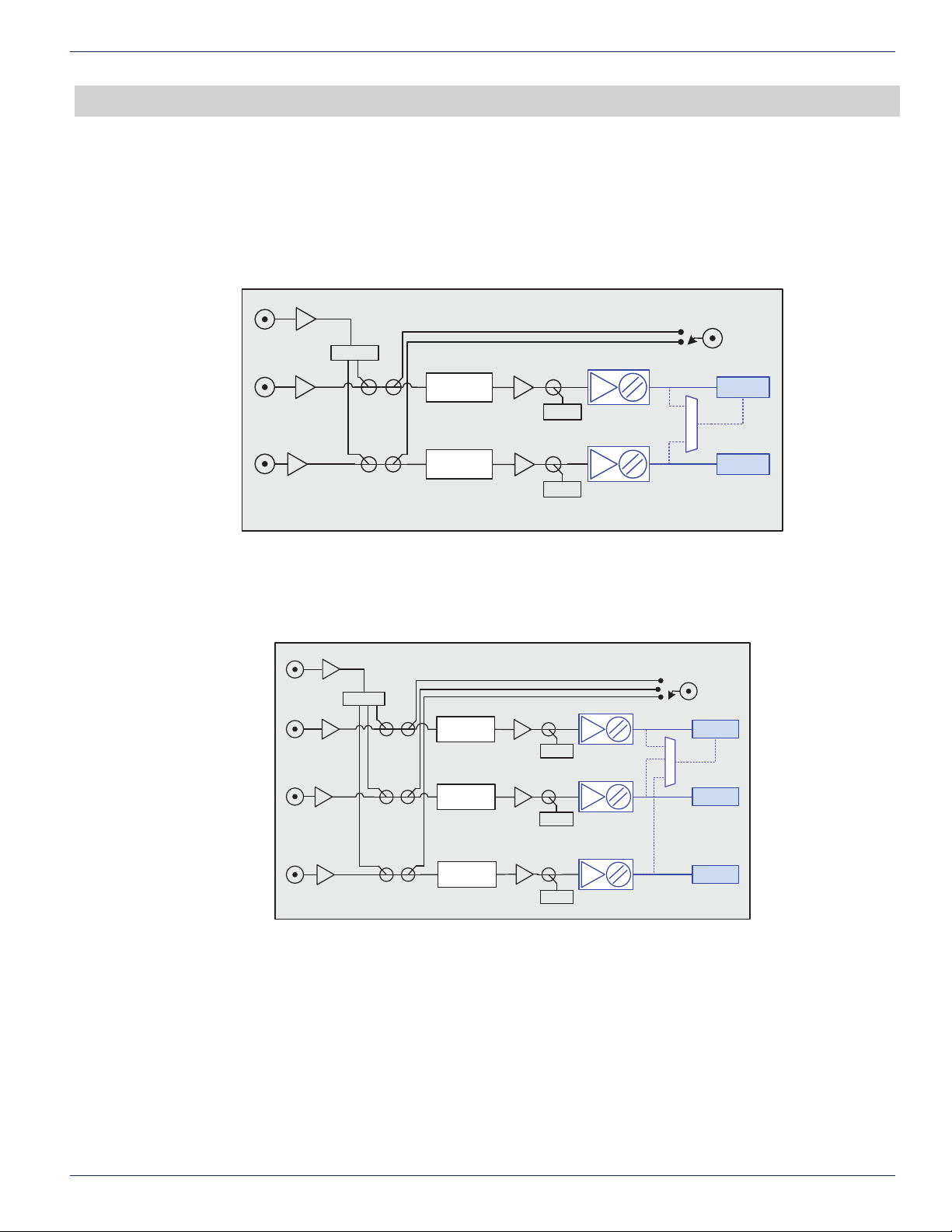
The following block diagrams depict the RF and optical signal ow through the DMT24, DMT34 and DMT44 transmitter
modules:
BC
Input
(*-4)
Splitter
CHAPTER 5:
Front Panel
Test Point - 10 dB
BLOCK DIAGRAM & OPERATION
NC1
(*-1)
NC2
(*-2)
* = card
number (1..8)
Figure 1: ChromaFlex DMT24 Transmitter Module Block Diagram
BC
Input
(*-4)
NC1
(*-1)
NC2
(*-2)
Splitter
Variable
Attenuator
Variable
Attenuator
Variable
Attenuator
Variable
Attenuator
RF Det.
ITU*
Opt. Mux
RF Det.
ITU*
OUT 1
OUT 2
DMT24
Front Panel
Test Point - 10 dB
RF Det.
RF Det.
ITU*
ITU*
Opt. Mux
OUT 1
OUT 2
NC3
(*-3)
* = card
number (1..8)
Variable
Attenuator
RF Det.
ITU*
OUT 3
DMT34
Figure 2: ChromaFlex DMT34 Transmitter Module Block Diagram
ChromaFlex DMT24, DMT34 & DMT44 Multi-Wavelength DWDM Direct Modulated Transmitter Module – Hardware Interface Manual 5-1
Page 16
CHAPTER 5:
BLOCK DIAGRAM & OPERATION
Input 1
(*-1)
Input 2
(*-2)
Input 3
(*-3)
Input 4
(*-4)
* = card
number (1..8)
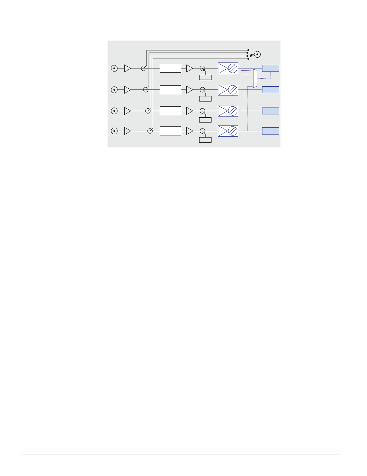
Figure 3: ChromaFlex DMT44 Transmitter Module Block Diagram
As seen in the block diagrams above and as described in Product Introduction, the DMT24 and DMT34 have internal RF
combining to merge a common broadcast RF input signal to each individual NC input. The DMT44 has no such combining
since all four rear F-ports are utilized for direct application to each laser segment in the quad module. After this initial
combining stage, all transmitter versions have the same functionality.
Front Panel
Test Point - 10 dB
Variable
Attenuator
RF Det.
Variable
Attenuator
RF Det.
Variable
Attenuator
RF Det.
Variable
Attenuator
RF Det.
ITU*
ITU*
ITU*
ITU*
Opt. Mux
DMT44
OUT 1
OUT 2
OUT 3
OUT 4
A directional coupler for each laser segment provides a sample of the full spectrum RF load applied to each laser to the
switchable female F-port on the front. This level is calibrated to be -10 dB relative to the input at the rear of the module,
regardless of AGC function of the module. The RF signal passes through a variable RF attenuator. The attenuator is
either automatically set through the feedback loop when operated in the AGC mode or may be set in the manual mode via
software interfaces. The signal is amplied and then passes through a directional coupler used to sample the RF signal for
remote monitoring and the AGC control loop back to the input variable attenuator. The through path is applied to a laser.
Fiber length adjustment for the laser is set through the software interfaces. The optical signal passes to each of the front
panel optical connectors. An internal multiplexer option is available in which case each wavelength is multiplexed internally
with the combined wavelengths connected to output port 1.
5-2 ChromaFlex DMT24, DMT34 & DMT44 Multi-Wavelength DWDM Direct Modulated Transmitter Module – Hardware Interface Manual
Page 17
FRONT PANEL
6. Front Panel
6.1 Front Panel Illustration
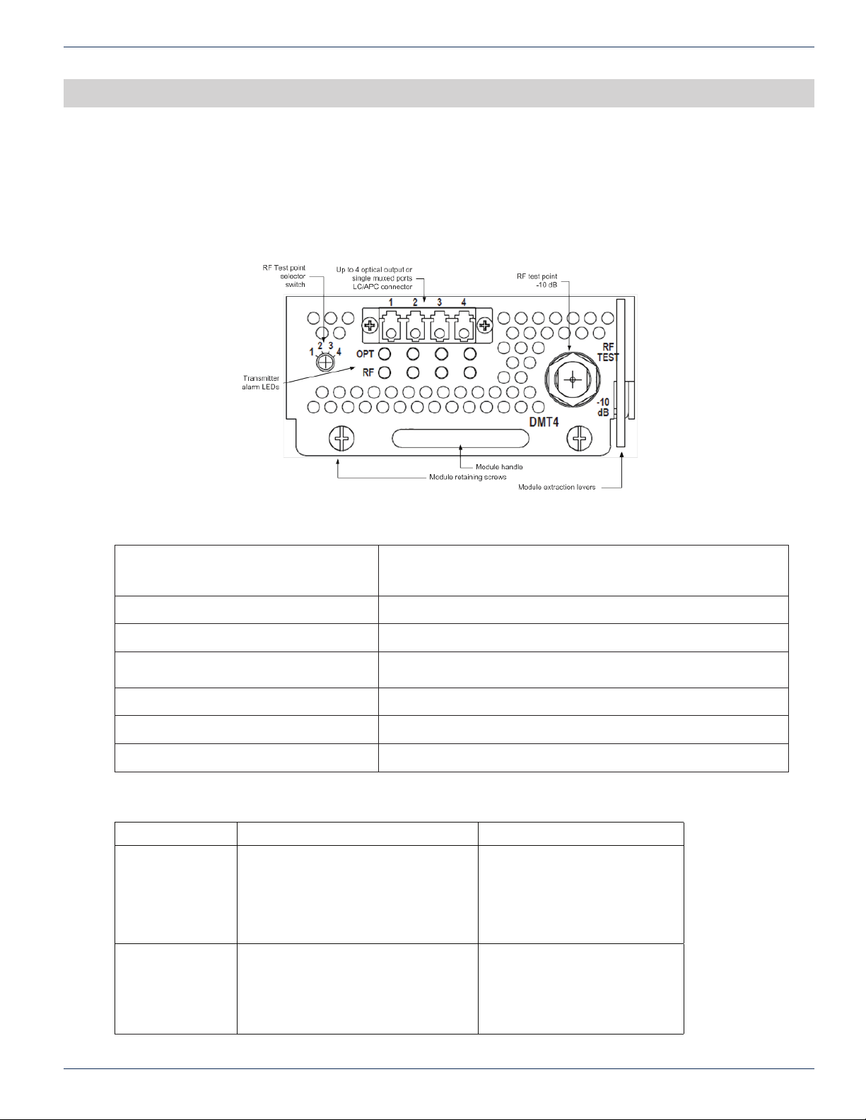
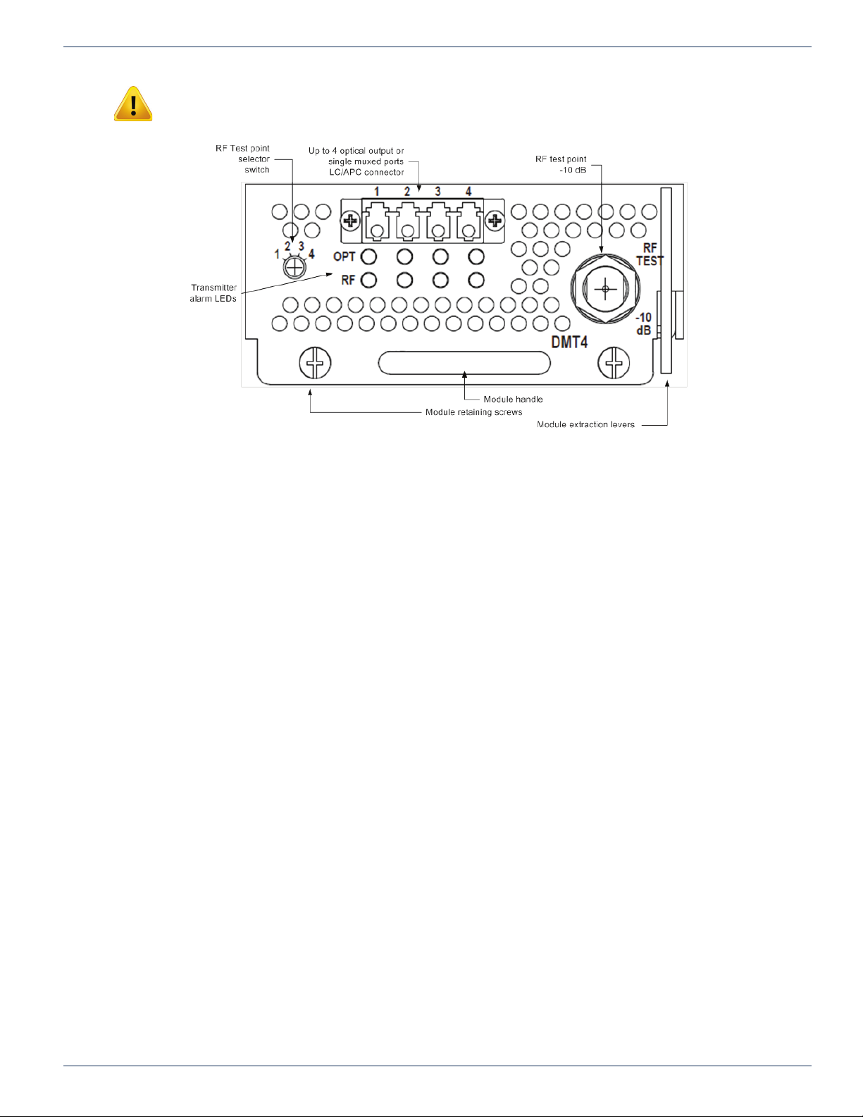
The following diagram and table depicts the features of the transmitter module front panel. The DMT44 module is shown for
reference. The DMT24 and DMT34 are labeled “NA” or “N” for the unused optical connector and RF test point selection.
CHAPTER 6:
FRONT PANEL
6.2 Table of Front Panel Features
Module Extraction Levers Lever assist in removing the module from the chassis backplane
Module Retaining Screws Secures the module to the chassis.
Module Handle Utilized to insert and remove the module.
RF Test Point -10 dB sample of the RF input to the module. Relative to RF input at
RF Test Point Selector Switch Selects the RF test point for transmitter 1 to 4.
Optical Output LC/APC Connector (OUT) Optical output signal connection.
Transmitter Alarm LEDs Visual alarm status indicators for each of the four transmitters.
6.3 Alarm Status Indicators
LED Function Value
OPT One LED for Each Laser 1 through 4
Optical Output Power
Laser Temperature
Module Temperature
Figure 4: Front Panel
connector.
rear of module.
Green = Normal
Amber = Minor Temp Alarm or Opt
Power +/- 1dB
Red = Major Temp Alarm or Opt
Power +/- 2 dB
RF One LED for Each Laser 1 through 4
Monitors the RF Drive Level to Each
Laser
For more information regarding alarm status and monitoring refer to the ChromaFlex Operation Manual.
ChromaFlex DMT24, DMT34 & DMT44 Multi-Wavelength DWDM Direct Modulated Transmitter Module – Hardware Interface Manual 6-1
Green = Normal
Amber = Minor Alarm, RF Out of
Range +/- 2 dB
Red = Major Alarm, RF Out of
Range +/- 3 dB
Page 18

CHAPTER 6:
FRONT PANEL
This page intentionally left blank.
6-2 ChromaFlex DMT24, DMT34 & DMT44 Multi-Wavelength DWDM Direct Modulated Transmitter Module – Hardware Interface Manual
Page 19

MODULE INSTALLATION
7. Module Installation
The DMTx4 (x=2, 3 or 4) transmitter module occupies a single ChromaFlex chassis module slot. The modules may be
inserted or removed while the chassis is powered without interrupting other operational modules in the chassis. The
following module installation procedures assume the chassis is installed and powered following the instructions in the
ChromaFlex Operation Manual.
1. Align the module into the desired slot opening in the ChromaFlex chassis.
2. Using the handle push the module into the slot with even pressure until the module is mated with the chassis midplane connector.
3. Press the module extraction levers downward against the module face.
4. Tighten the two module retaining screws until snug in an even manner.
5. The module LEDs should now be lit with the four OPT LEDs green and the four RF LEDs red (DMT44) if RF has not
already been connected to the chassis rear panel RF connectors.
CHAPTER 7:
MODULE INSTALLATION
ChromaFlex DMT24, DMT34 & DMT44 Multi-Wavelength DWDM Direct Modulated Transmitter Module – Hardware Interface Manual 7-1
Page 20

CHAPTER 7:
MODULE INSTALLATION
This page intentionally left blank.
7-2 ChromaFlex DMT24, DMT34 & DMT44 Multi-Wavelength DWDM Direct Modulated Transmitter Module – Hardware Interface Manual
Page 21
MODULE CONNECTIONS
8. Module Connections
The following describes the initial RF and optical connections to the chassis and module.
8.1 RF Connections
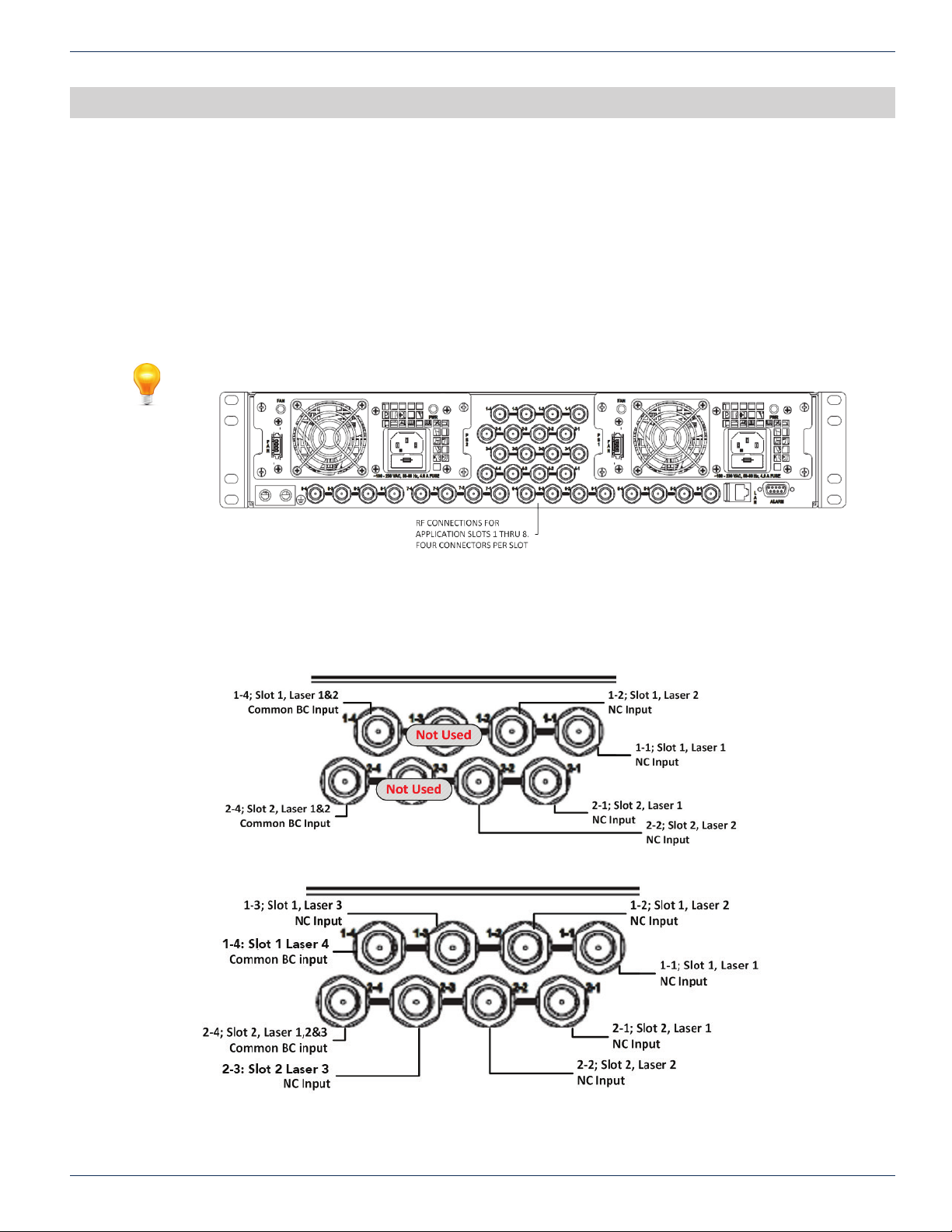
RF connections are made at the back of the ChromaFlex chassis. The DMT24 and DMT34 have one broadcast input
which is shared across each laser transmitter and two or three narrowcast inputs for the dedicated services to each laser
transmitter. The DMT44 has a single RF input for each laser transmitter where the common broadcast and each individual
laser transmitter narrowcast channels is externally combined prior to connection to the chassis.
NOTE: Each laser transmitter should have the same common RF channel content below 270 MHz.
CHAPTER 8:
MODULE CONNECTIONS
Figure 5: RF Connections
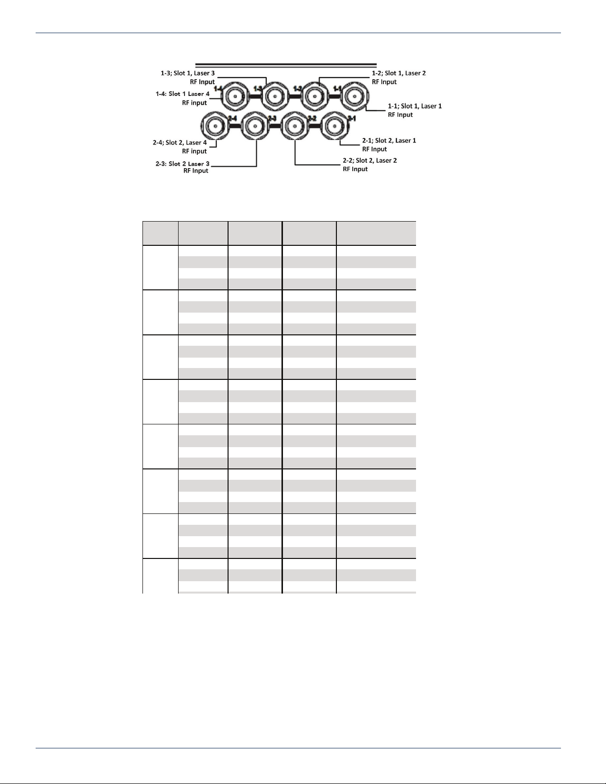
The following table and diagrams show the corresponding RF connector to module slots for the DMTx4 transmitter modules.
The RF connector numbering corresponds to the chassis slot number – laser transmitter number. For example, RF
connector 1-1 is connected to chassis slot 1- laser transmitter 1 within the module. RF connector 1-2 is connected to chassis
slot 1- laser transmitter 2 within the module.
Figure 6: DMT24 – Rear Panel RF Connections
Figure 7: DMT34 – Rear Panel RF Connections
ChromaFlex DMT24, DMT34 & DMT44 Multi-Wavelength DWDM Direct Modulated Transmitter Module – Hardware Interface Manual 8-1
Page 22
1-1 Narrowcast 1 Narrowcast 1 RF 1
1-2 Narrowcast 2 Narrowcast 2 RF 2
1-3 N/A Narrowcast 3 RF 3
1-4 Broadcast Broadcast RF 4
2-1 Narrowcast 1 Narrowcast 1 RF 1
2-2 Narrowcast 2 Narrowcast 2 RF 2
2-3 N/A Narrowcast 3 RF 3
2-4 Broadcast Broadcast RF 4
3-1 Narrowcast 1 Narrowcast 1 RF 1
3-2 Narrowcast 2 Narrowcast 2 RF 2
3-3 N/A Narrowcast 3 RF 3
3-4 Broadcast Broadcast RF 4
4-1 Narrowcast 1 Narrowcast 1 RF 1
4-2 Narrowcast 2 Narrowcast 2 RF 2
4-3 N/A Narrowcast 3 RF 3
4-4 Broadcast Broadcast RF 4
5-1 Narrowcast 1 Narrowcast 1 RF 1
5-2 Narrowcast 2 Narrowcast 2 RF 2
5-3 N/A Narrowcast 3 RF 3
5-4 Broadcast Broadcast RF 4
6-1 Narrowcast 1 Narrowcast 1 RF 1
6-2 Narrowcast 2 Narrowcast 2 RF 2
6-3 N/A Narrowcast 3 RF 3
6-4 Broadcast Broadcast RF 4
7-1 Narrowcast 1 Narrowcast 1 RF 1
7-2 Narrowcast 2 Narrowcast 2 RF 2
7-3 N/A Narrowcast 3 RF 3
7-4 Broadcast Broadcast RF 4
8-1 Narrowcast 1 Narrowcast 1 RF 1
8-2 Narrowcast 2 Narrowcast 2 RF 2
8-3 N/A Narrowcast 3 RF 3
8
DMT34
DMT44
(BC & NC external combine)
3
4
5
6
7
Modul e
Slot
Rear Panel
Connector
DMT24
1
2
CHAPTER 8:
MODULE CONNECTIONS
Figure 8: DMT44 – Rear Panel RF Connections
8.2 Optical Connections
8-2 ChromaFlex DMT24, DMT34 & DMT44 Multi-Wavelength DWDM Direct Modulated Transmitter Module – Hardware Interface Manual
There are many different optical system congurations that are possible with the ChromaFlex DMTx4 transmitter.
The transmitter may have individual output ports per laser transmitter or they can be optioned with an internal optical
multiplexer with all wavelengths combined to a single optical output on port number 1. Your specic design may include
additional components such as external multiplexers, an EDFA, return path receivers, destacker modules or other external
components.
Page 23
CHAPTER 8:
MODULE CONNECTIONS
Important Note: Always clean and inspect optical connectors prior to making a connection to the
DMTx4 optical ports. Never look into an optical connector when a signal is present.
Figure 9: Optical Connections
Please take the following steps for rst time set up of the unit.
• Identify the transmitter unit at the corresponding slot location.
• Connect each output port (1 through 4) to a ber jumper utilizing a good quality clean LC/APC connector to the next
device or ber cable per your speci c design schematic drawing.
ChromaFlex DMT24, DMT34 & DMT44 Multi-Wavelength DWDM Direct Modulated Transmitter Module – Hardware Interface Manual 8-3
Page 24

CHAPTER 8:
MODULE CONNECTIONS
This page intentionally left blank.
8-4 ChromaFlex DMT24, DMT34 & DMT44 Multi-Wavelength DWDM Direct Modulated Transmitter Module – Hardware Interface Manual
Page 25

MODULE SET-UP
9. Module Set-up
9.1 Setting RF Input Levels
The RF signals that are common to each laser transmitter are connected to the Broadcast (BC) input port as shown in the
rear panel connector table in section 6.1. The common RF loading into the BC RF input port should occupy the RF spectrum
to at least approximately 270 MHz to avoid SRS crosstalk degradation.
The Narrowcast (NC) signals for each of the individual laser transmitters is connected to the corresponding input port
as shown in the rear panel connector table in section 6.1. Note that the NC input should be all QAM signals and above
270 MHz. The RF combining is performed externally for the DMT44 module with four laser transmitters. Follow the same
guidelines for combining BC and NC RF signals as described above.
Determining the proper rear panel RF input level is important to ensure optimum transmitter performance. The following will
provide guidance in calculating the proper adjustment to the per channel RF level for your actual channel loading from the
reference channel loading and the total RF input power requirement.
Each DMTx4 transmitter is factory optimized for a rear panel nominaltotal input power of +31 dBmV for the combined BC
and NC signals. This level provides 3 to 4 dB of reserve gain for the AGC operation. The reserve gain is the amount of
headroom below the +31 dBmV reference level.
CHAPTER 9:
MODULE SET-UP
9.1.1 All QAM Channels
The all QAM reference channel loading and per channel input level is 155 ITU-T J.83 Annex B QAM 256 channels between
54-1002 MHz set to 9 dBmV. The RF per channel level of 9 dBmV is calculated from the total power as follows:
Total Power - [10*log
31 dBmV - [10*log
(channel load)]
10
(155)] = 31 dBmV – 22 = 9 dBmV
10
Using the same formula to adjust for a lower channel loading such as a 750 MHz system with 110 channels:
31 dBmV - [10*log
(110)] = 31 dBmV – 20.4 = 10.6 dBmV
10
Therefore with 110 of all QAM channel loading the correct rear panel RF input level is 10.6 dBmV at the input of both the BC
and NC ports.
9.1.2 Mix of Analog & QAM Channels
The mix of Analog and QAM reference channel loading and per channel input level is 30 NTSC analog (54-258 MHz) set to
13 dBmV and 124 ITU-T J.83 Annex B QAM 256 channels (258-1002 MHz) set to 11 dBmV. The RF level per channel for
analog and QAM is calculated from the total power as follows:
Since there is a 6 dB power level difference between the QAM and analog channels it is easier if we convert the QAM
channels to an equivalent analog power level in the formula below. The QAM RF level being 6 dB lower means the QAM
power level is 1/4
Total Power - [10*log
31 dBmV - [10*log
Therefore the analog channels are set to 13 dBmV and the QAM channels are 6 dB lower or 11 dBmV.
Use the same formula to increase the number of analog channels to 60 and decrease the number of QAM channels to 94
and calculate the correct input level for each:
31 dBmV - [10*log
Therefore the analog channels are set to 12 dBmV and the QAM channels 6 dB lower or 6 dBmV.
th
the analog level. As a point of reference, -3 dB is 1/2 power and -6 dB is 1/4 power.
(Analog channel load)+(QAM channel load/4)]
10
((30)+(124/4))] = 31 dBmV – 18 = 13 dBmV
10
((60)+(94/4))] = 31 dBmV – 19 = 12 dBmV
10
9.2 Conguring The DMTx4 Transmitter Module
To set-up, congure and verify the RF drive level for the DMTx4 requires the operator to become familiar with the Handheld Display or GUI status and conguration menus. Refer to the ChromaFlex Chassis – Hardware Interface Manual as a
supplement to the following procedures which will reference the associated display parameters.
The following DMTx4 Hand-held Display menu tree will assist in navigating the Hand-held Display.
ChromaFlex DMT24, DMT34 & DMT44 Multi-Wavelength DWDM Direct Modulated Transmitter Module – Hardware Interface Manual 9-1
Page 26

Greeting:
InnoTrans Communications
DMTX
Power(dBm)
RF Lvl(dB)
Tx Attn (dB)
Temp(C)
Lambda(nm)
Prev Menu
Setup
Mode
Settings
Sel_Ch
Mode
Save
Prev Menu
Gain
Settings
Sel_Ch
RF Lvl(rdB)
Gain(Steps)
Save
Prev Menu
Alarm
Laser Temperature
Laser Pwr
RF Level
Unit Temp
Prev Menu
Status
Chassis
Temperature(C)
Model
Hardware Version
Software Version
Serial Number
Prev Menu
Tx Fiber
Length
Sel_Ch
Length (km)
Save
Prev Menu
Prev Menu
CHAPTER 9:
MODULE SET-UP
9.2.1 AGC Mode (Hand-held Display)
Operating in the AGC mode provides for plug-and-play RF level setting as the transmitter automatically sets the internal
attenuators for the optimal laser drive level and OMI. When in the AGC mode the variable attenuators will automatically
be adjusted for each laser transmitter so the RF reference display will read 0.0 dB ± 0.5 dB. The following provides the
procedures and associated menus for conguring the DMTx4 with the Hand-held Display in the AGC mode.
1. Connect power to the chassis. Unit should power up (no switches).
2. Plug the RS-232 cable from the Hand-held Display into the RS-232 port on the CF-CTLR control and communications
module.
3. Using the Hand-held Display choose the appropriate slot for the desired module location.
4. Example DMT34 - With a combined Broadcast/Narrowcast total RF power of 31 dBmV plug the Broadcast cable into
9-2 ChromaFlex DMT24, DMT34 & DMT44 Multi-Wavelength DWDM Direct Modulated Transmitter Module – Hardware Interface Manual
Page 27

port 1-4, Narrowcast cable into port 1-1 to 1-3. (see section 6.1)
RF : -0.1
Att(dB): +3.5
S etup Menu
Tx Status Menu
M od e Setting Menu
Gain S etting Me nu
M ode: MGC
Save : No ( AGC)
S ave: Yes (MGC)
Prev Menu
G ain Setting Menu
OPTOut Setting Menu
Rf Lv l (rd B): -1.0
Gain(steps): 4.5
Rf Lv l (rdB): -0.1
Gain(steps): -3.5
Gain(steps): -3.5
S ave: Yes (-3.5)
Tx Status Menu
Alar m Men u
5. From the front panel RF Test Point conrm the Narrowcast QAM RF channels are at the same level as the Broadcast
QAM RF channels. If not, correct the level difference coming into the chassis on each individual NC port.
6. Using the Hand-held Display navigate to the Tx Setup Menu.
7. Under the Tx Status menu the RF (reference level) reading should be approximately 0.0 dB, ± 0.5 dB. The Att (dB)
(reserve gain level) should be between 3-4 dB (if 31 dBmV total RF power is applied to input ports).
The reserve gain is the amount of headroom below the +31 dBmV reference level.
9.2.2 MGC Mode (Hand-held Display)
The following provides the procedures and associated menus for conguring the DMTx4 with the Hand-held Display in the
MGC mode. When operating in the MGC mode the variable attenuator for each laser transmitter can be manually adjusted
to so the RF reference display will read 0.0 dB ± 0.5 dB.
1. Connect power to the chassis. Unit should power up (no switches).
2. Plug the RS-232 cable from the Hand-held Display into the RS-232 port on the CF-CTLR control and communications
module.
3. Using the Hand-held Display choose the appropriate slot for the desired module location.
4. Example DMT34 - With a combined Broadcast/Narrowcast total RF power of 31 dBmV plug the Broadcast cable into
port 1-4, Narrowcast cable into port 1-1 to 1-3. (see section 8.1)
5. From the front panel RF Test Point conrm the Narrowcast QAM RF channels are at the same level as the Broadcast
QAM RF channels. If not, correct the level difference coming into the chassis on each individual NC port.
6. Using the Hand-held Display navigate to the Setup/Mode Settings menu.
CHAPTER 9:
MODULE SET-UP
7. Under the Setup/Mode Settings menu place the unit in MGC mode and save the setting.
8. Next using the Hand-held Display navigate to the Setup/Gain Settings menu.
9. Select the internal laser transmitter to be adjusted (Sel_Ch)
10. Under the Gain Setting Menu note the RF Lvl.
11. Using the Gain (Steps) menu add or remove the attenuation steps until the RF Lvl displays 0.0 dB - ± 0.5 dB in the
Tx Status/RF menu.
12. Save Gain (Steps) value.
13. Next using the Hand-held Display navigate to the Tx Status menu.
ChromaFlex DMT24, DMT34 & DMT44 Multi-Wavelength DWDM Direct Modulated Transmitter Module – Hardware Interface Manual 9-3
14. Under the Tx Status Menu note the RF level. The level should be the same value as the RF Lvl value set in step #10.
The Att (dB) value should be +3.5 ± 0.5 dB with a total combined input power of 31 dBmV at the back of the chassis.
Page 28

RF : -0.1
Att(dB): +3.5
S etup Menu
Tx Status Menu
M ode Setting Menu
Tx Fiber Length:
CHAPTER 9:
MODULE SET-UP
15. Repeat the RF adjustment steps for each laser transmitter.
9.3 Setting Transmitter Fiber Length
The ber link length that each laser transmitter will propagate through needs to be entered to achieve optimal distortion
performance.
1. Using the Hand-held Display navigate to the Setup/Mode Settings/TX Fiber Length menu.
2. Select the internal laser transmitter to be adjusted (Sel_Ch).
3. Enter the ber length in km associated with the selected laser transmitter. This should not be based on distance
measured on a map. Use an optical TDR for proper ber length.
4. Repeat for each laser transmitter.
9-4 ChromaFlex DMT24, DMT34 & DMT44 Multi-Wavelength DWDM Direct Modulated Transmitter Module – Hardware Interface Manual
Page 29
TROUBLESHOOTING THE DMTX4
10. Troubleshooting The DMTx4
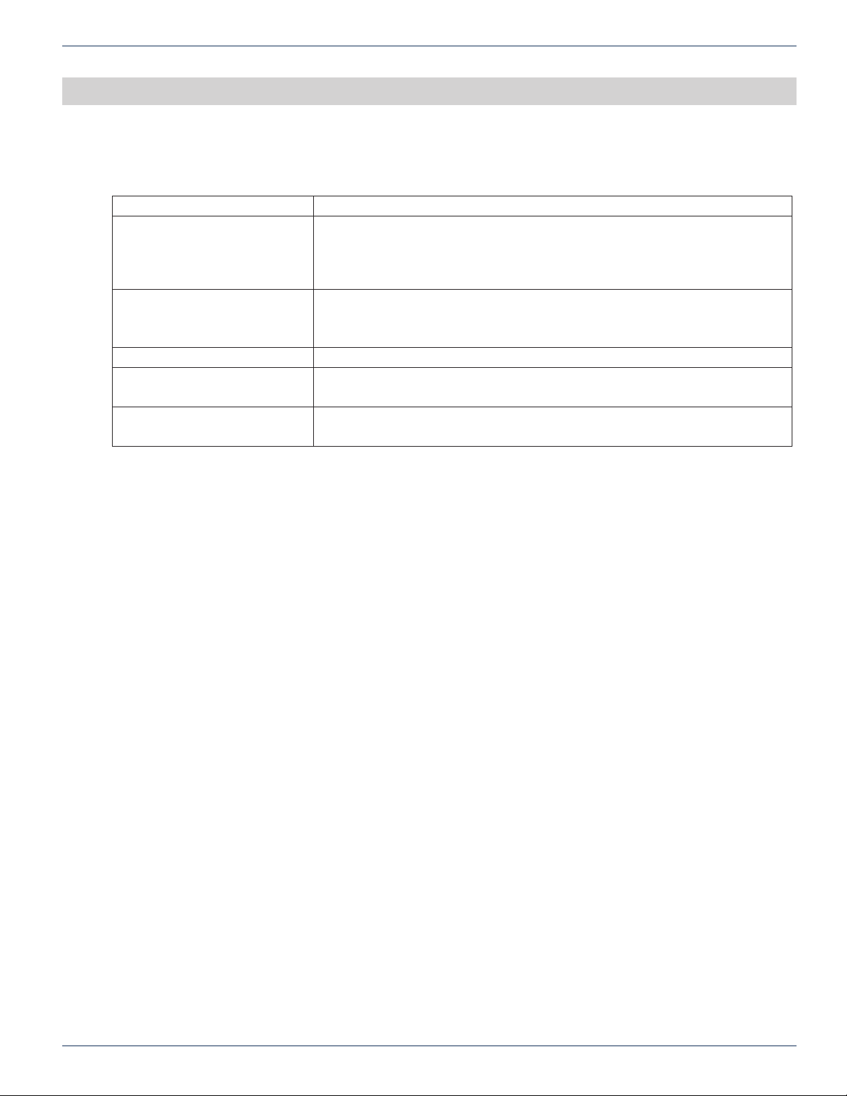
Condition Steps to Check
Power LED OFF (AC) Check if Power Cable is plugged in and Power Switch is in ON position.
Verify AC Outlet is Functional and conrm fuse on the AC feed is ne, replacing it if
necessary.
Look for other signs of life in unit like running fan, LCD display etc.
Power LED OFF (DC) Verify DC Feed is active and fuse is intact on fuse panel.
Verify DC Feed is not reversed.
Look for other signs of life in unit like running fan, LCD display etc.
Optical LED is Amber or Red Check output light level.
RF LED is Amber or Red Check RF Input level.
If in MGC mode Attn set too high (or too low if overdriving RF inputs).
Communication Issue with Unit Please conrm set-up is as described in the User Interface document.
If problem persists, please contact customer service for further help.
CHAPTER 10:
TROUBLESHOOTING THE DMTX4
ChromaFlex DMT24, DMT34 & DMT44 Multi-Wavelength DWDM Direct Modulated Transmitter Module – Hardware Interface Manual 10-1
Page 30

CHAPTER 10:
TROUBLESHOOTING THE DMTX4
This page intentionally left blank.
10-2 ChromaFlex DMT24, DMT34 & DMT44 Multi-Wavelength DWDM Direct Modulated Transmitter Module – Hardware Interface Manual
Page 31

SERVICE & SUPPORT
11. Service & Support
11.1 Contact ATX Networks
Please contact ATX Technical Support for assistance with any ATX products.
TECHNICAL SUPPORT
CUSTOMER SERVICE
ATX Networks
5850 Hellyer Avenue
San Jose, CA 95138 USA
CHAPTER 11:
SERVICE & SUPPORT
11.2 Warranty Information
All of ATX Networks’ products have a 1-year warranty that covers manufacturer’s defects or failures.
ChromaFlex DMT24, DMT34 & DMT44 Multi-Wavelength DWDM Direct Modulated Transmitter Module – Hardware Interface Manual 11-1
Page 32

ISO
REGISTERED
9001:15
© 2018 ATX Networks
Information in this document is subject to change without notice.
Rev. 09/18 (ANW1169)
ATX Networks
1-501 Clements Road West, Ajax, ON L1S 7H4 Canada
Tel: 905.428.6068 | Toll Free: 800.565.7488 | [email protected]
www.atxnetworks.com
 Loading...