

Page 1

ChromaFlex
ChromaFlex CPA EDFA
HARDWARE INTERFACE MANUAL
www.atxnetworks.com
www.atx.com
Page 2

Although every effort has been taken to ensure the accuracy of this document it may be necessary, without notice, to make amendments or correct omissions.
Specications subject to change without notice.
Products or features contained herein may be covered by one or more U.S. or foreign patents. Other non-ATX product and company names in this manual are the property of their respective
companies.
Page 3

TABLE OF CONTENTS
1. PRODUCT INTRODUCTION ............................................. 1-1
2. UNPACKING & INSPECTING A NEW UNIT ................................. 2-1
2.1 What To Do About Physical Damage .................................. 2-1
2.2 What To Do About Concealed Damage ................................ 2-1
2.3 How To Return Equipment .......................................... 2-1
3. SPECIFICATIONS ...................................................... 3-1
4. BLOCK DIAGRAM & OPERATION ........................................ 4-1
5. FRONT PANEL ....................................................... 5-1
5.1 Front Panel Illustration ............................................. 5-1
5.2 Table of Front Panel Features ....................................... 5-1
5.3 Alarm Status Indicators ............................................. 5-2
6. MODULE INSTALLATION ............................................... 6-1
7. MODULE CONNECTIONS ............................................... 7-1
7.1 Optical Connections ............................................... 7-1
8. MODULE SETUP ...................................................... 8-1
9. TROUBLESHOOTING THE CF-CPA EDFA MODULE ......................... 9-1
10. SERVICE & SUPPORT ................................................. 10-1
13.1 Contact ATX Networks ............................................ 10-1
13.2 Warranty Information ............................................. 10-1
ChromaFlex CPA EDFA – Hardware Interface Manual iii
ATX Condential & Proprietary
Page 4

This page intentionally left blank.
iv ChromaFlex CPA EDFA – Hardware Interface Manual
ATX Condential & Proprietary
Page 5

PRODUCT INTRODUCTION
1. Product Introduction
The ChromaFlex CF-CPA EDFA is a high density single slot module for the ChromaFlex chassis. The CF-CPA is a Constant
Power Amplier therefore the composite output power remains the same over the specied range of optical input level. The
EDFA composite gain, gain per wavelength and per wavelength output power will change with a change in the number of
wavelengths or composite input power to maintain a constant output power.
Features of the CF-CPA EDFA include:
• Low noise gure
• Constant output power
• Optional integrated return path reect port
• Front panel visual status indicators
• Input and output test points
• Setup and manage via SNMP, CLI, web GUI, local craft port
The CF-EDFA may include an optional integrated optical lter for applications where upstream optical signals need to be
removed and routed to other termination equipment such as retrun path receivers or destacker modules.
CHAPTER 1:
PRODUCT INTRODUCTION
ChromaFlex CPA EDFA – Hardware Interface Manual 1-1
ATX Condential & Proprietary
Page 6

CHAPTER 1:
PRODUCT INTRODUCTION
This page intentionally left blank.
1-2 ChromaFlex CPA EDFA – Hardware Interface Manual
ATX Condential & Proprietary
Page 7

UNPACKING & INSPECTING A NEW UNIT
2. Unpacking & Inspecting a New Unit
Before shipment, ATX inspects and packs all the essential items carefully. Nevertheless, damage may occur during
shipment. The carrier assumes full responsibility for a safe delivery of the equipment.
1. Inspect the package for any physical damage.
2. Open the package.
3. Remove any packing material.
4. Inspect the unit for any physical damage.
5. Shake the unit with care, paying attention to any rattling loose parts that may suggest a concealed damage (some
noise due to moving cables is normal).
6. Check for any missing accessories.
When any damage is noticed to the merchandise, please notify customer service (see Service & Support section) and le a
claim with the carrier as noted below.
2.1 What To Do About Physical Damage
Record any evidence of physical damage or loss on the freight bill or receipt and have the carrier’s agent sign it. If you fail
to do so, the carrier may refuse to honor the damage claim. The carrier will supply you with any forms required to le such a
claim.
CHAPTER 2:
UNPACKING & INSPECTING A NEW UNIT
2.2 What To Do About Concealed Damage
Damage which is not apparent until the unit has been unpacked is considered concealed damage. The contents may have
been damaged due to rough handling even if there is no external evidence. If you should notice damage upon unpacking the
unit you should make a written request for inspection by the carrier’s agent within 10 days of the delivery date. Afterwards
le a claim with the carrier.
2.3 How To Return Equipment
Call customer service (see Service & Support section) for a Return Materials Authorization (RMA) number. You will need the
unit’s serial number, description of the problem, and some shipping information. We must receive the unit within thirty (30)
days from the date a RMA number is issued. If for any reason, you want to ship the unit 30 days after the RMA number has
been issued, you must obtain a new RMA number by calling customer service. Units received without an RMA number or
one with an expired RMA number will not be accepted by our receiving department.
ChromaFlex CPA EDFA – Hardware Interface Manual 2-1
ATX Condential & Proprietary
Page 8

UNPACKING & INSPECTING A NEW UNIT
CHAPTER 2:
This page intentionally left blank.
2-2 ChromaFlex CPA EDFA – Hardware Interface Manual
ATX Condential & Proprietary
Page 9

SPECIFICATIONS
3. Specications
Please refer to the ChromaFlex EDFA Optical Amplier Module spec sheet located at www.atxnetworks.com under User
Documents for product specications.
CHAPTER 3:
SPECIFICATIONS
ChromaFlex CPA EDFA – Hardware Interface Manual 3-1
ATX Condential & Proprietary
Page 10

SPECIFICATIONS
CHAPTER 3:
This page intentionally left blank.
3-2 ChromaFlex CPA EDFA – Hardware Interface Manual
ATX Condential & Proprietary
Page 11
BLOCK DIAGRAM & OPERATION
Circulator EP
4. Block Diagram & Operation
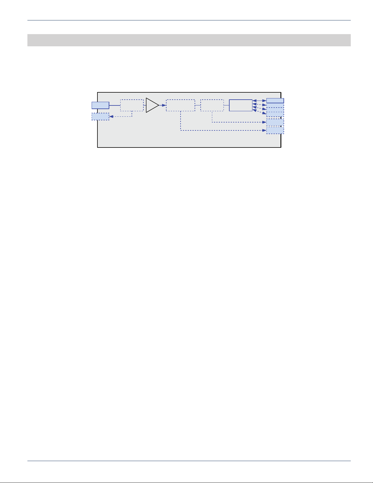
The following block depicts the optical signal ow and control bus through the CF-CPA EDFA module.
CHAPTER 4:
BLOCK DIAGRAM & OPERATION
IN
TP
5%
Coupler
Opt. IP TP Variable Gain
+G
Filter or
Circulator1%Coupler
Opt. OP TP
Opt. EP
Optional
1,2,4-way
OUT 1
OUT 2
OUT 3
OUT 4
TP
R-EP
CF-CPA-00*
Figure 4-1: CF-CPA EDFA Module Block Diagram
The CF-CPA is a Constant Power Amplier therefore the composite output power remains the same over the specied range
of optical input level. Thus the EDFA composite gain, gain per wavelength and per wavelength output power will change
with a change in the number of wavelengths or composite input power applied to the EDFA to maintain a constant output
power. The CF-CPA is primarily utilized as a headend launch amplier applications with a xed number of wavelengths.
Optical signals in the 1530 nm to 1562 nm range are connected to the front panel optical input LC connector and rst pass
through an input coupler/isolator. The optical channels within the spectrum are then connected to the Erbium Doped Fiber
& multiplexer gain stage where a pump laser is multiplexed with the input signal resulting in an amplied output signal.
The output of the gain stage is connected to the output side coupler/isolator. The input and output coupler provides a
reference signal to the micro-processor control circuitry which adjusts the pump laser and gain stage to maintain a constant
composite output power with changes to the composite input power. The micro-processor also provides status monitoring
signaling to the ChromaFlex chassis. The amplied output signal may be connected to an optional lter or circulator type of
Express Port for inserting additional optical channels or extracting channels. A lter is typically utilized if the optical channels
are separated in different bands and a circulator is utilized if channels in the upstream direction are interleaved with the
downstream signals passing through the EDFA. Circulator example, utilizing downstream wavelengths of (20,21,22,23)
upstream 24, downstream (25,26,27,28) upstream 29. The upstream channels 24 and 29 would be directed to the R-EP
port. Note that the circulator is directional and cannot be utilized for combing purposes, only upstream extraction. A 5%
coupler test point is provided at the output of the EDFA.
ChromaFlex CPA EDFA – Hardware Interface Manual 4-1
ATX Condential & Proprietary
Page 12

CHAPTER 4:
BLOCK DIAGRAM & OPERATION
This page intentionally left blank.
4-2 ChromaFlex CPA EDFA – Hardware Interface Manual
ATX Condential & Proprietary
Page 13
FRONT PANEL
5. Front Panel
5.1 Front Panel Illustration
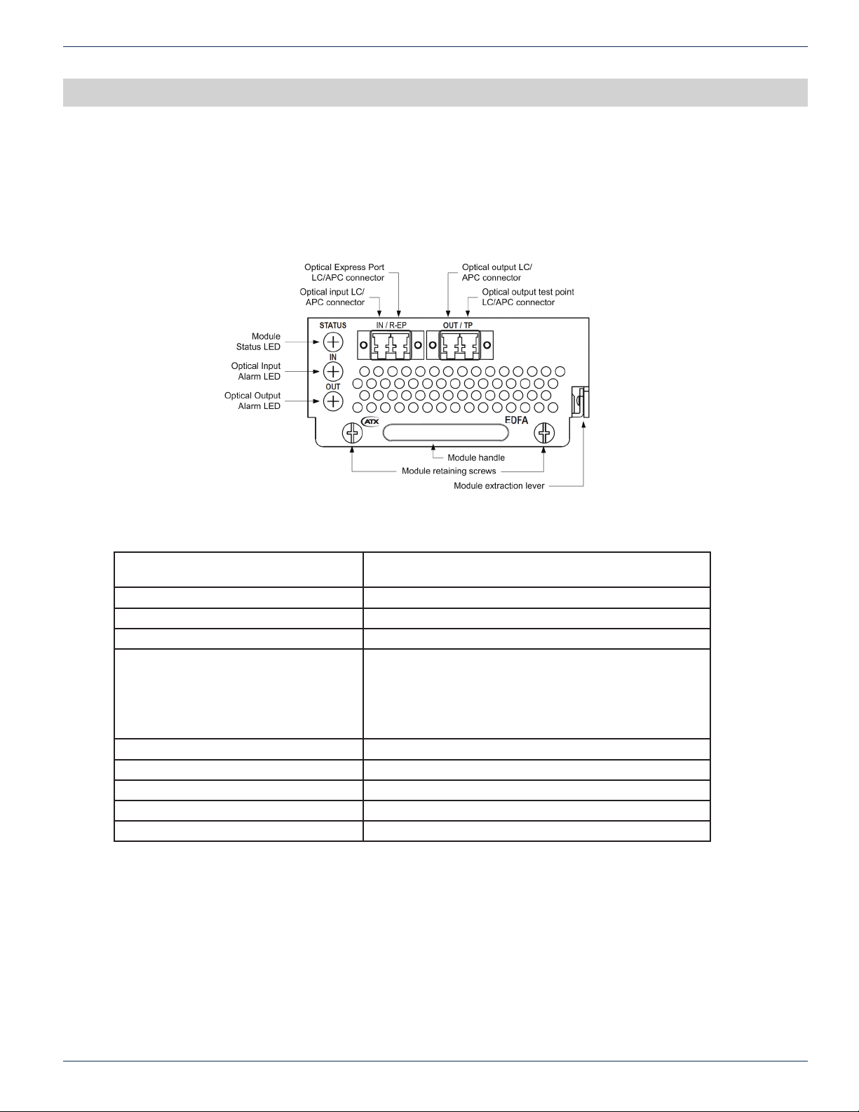
The following diagram and table depicts the features of the CF-CPA EDFA module front panel.
CHAPTER 5:
FRONT PANEL
5.2 Table of Front Panel Features
Module extraction lever Lever to assist in removing the module from the chassis
Module retaining screws Secures the module to the chassis.
Module handle Utilized to insert and remove the module.
Optical input LC/APC connector (IN) Optical input signal connection.
(Optional) Express Port (R-EP) Utilized to extract or combine additional optical signals to or
Optical output LC/APC connector (OUT) Optical output signal LC/APC connection.
Optical output test point (TP) Optical test point (5% value) LC/APC connector.
Status Alarm LED Visual indicator of module temperature alarm.
Optical Input Alarm LED Visual optical input power alarm status.
Optical Output Alarm LED Visual optical output power alarm status.
backplane connector.
from other equipment. 1260 to 1620 nm. Either a circulator
or ltered Express Port may be ordered. Verify which is
utilized in your application.
Important Note: be certain not to combine same channels.
ChromaFlex CPA EDFA – Hardware Interface Manual 5-1
ATX Condential & Proprietary
Page 14
CHAPTER 5:
FRONT PANEL
5.3 Alarm Status Indicators (CF-CPA)
LED Function Value
STATUS Module temperature Green = Normal
Optical Input Monitors the optical input power Green = Normal
Optical Output Monitors the optical output power Green = Normal
Amber = Minor Temp alarm
Red = Major Temp alarm
Amber = Minor alarm -1 to -2 dB below
input range
Red = Major alarm >-2 dB below input
range
Amber = Minor alarm -1 to -2 dB below
rated output power
Red = Major alarm >-2 dB below rated
output power
5-2 ChromaFlex CPA EDFA – Hardware Interface Manual
ATX Condential & Proprietary
Page 15

MODULE INSTALLATION
6. Module Installation
The CF-CPA Constant Power EDFA module occupies a single ChromaFlex chassis module slot. The modules may be
inserted or removed while the chassis is powered without interrupting other operational modules in the chassis. The
following module installation procedures assume the chassis is installed and powered following the instructions in the
ChromaFlex Chassis Hardware Interface Manual.
1. Align the module into the desired slot opening in the ChromaFlex chassis
2. Using the handle push the module into the slot with even pressure until the module is mated with the chassis midplane connector.
3. Press the modules extraction levers downward against the module face.
4. Tighten the two module retaining screws until snug in an even manner.
5. The module Status LEDs should now be lit green and the optical input and output power LEDs red if an optical input
has not already been connected to the module. Note, each LED will cycle through all colors during a power up cycle.
CHAPTER 6:
MODULE INSTALLATION
ChromaFlex CPA EDFA – Hardware Interface Manual 6-1
ATX Condential & Proprietary
Page 16

CHAPTER 6:
MODULE INSTALLATION
This page intentionally left blank.
6-2 ChromaFlex CPA EDFA – Hardware Interface Manual
ATX Condential & Proprietary
Page 17
MODULE CONNECTIONS
7. Module Connections
7.1 Optical Connections
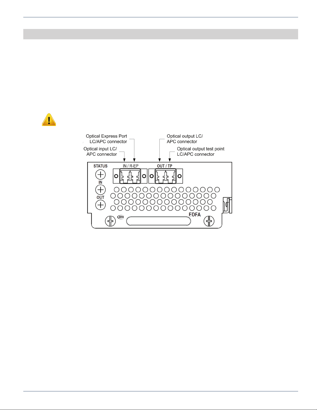
The CF-CPA EDFA has one optical input port, one optical output port, one optional optical express port which may lter or
re ect additional optical signals to other equipment and an output test point.
Please follow your speci c design schematic for interconnecting additional equipment while paying attention to the optical
levels speci ed for your application.
Important Note: Always clean and inspect optical connectors prior to making a connection to the
CF-CPA optical ports. Never look into an optical connector when a signal is present.
CHAPTER 7:
MODULE CONNECTIONS
1. Check the input optical level with a power meter to be certain it is within the input operational range of the EDFA.
Once the levels are veri ed, connect the cleaned LC/APC connector to the EDFA optical input port. You should
observe the optical input and output LED change from Red to Green if a signal is present.
2. Connect a clean LC/APC jumper to the EDFA output port and verify the composite optical power level matches the
speci cation.
3. The optional express port may be utilized for extracting or combining additional wavelengths with the wavelengths
connected to the input and ampli ed by the EDFA module. In the case of extracting, connect a power meter to the
express port with a clean LC/APC jumper and verify the level of the desired optical signal.
ChromaFlex CPA EDFA – Hardware Interface Manual 7-1
ATX Confi dential & Proprietary
Page 18

CHAPTER 7:
MODULE CONNECTIONS
This page intentionally left blank.
7-2 ChromaFlex CPA EDFA – Hardware Interface Manual
ATX Condential & Proprietary
Page 19

MODULE SETUP
8. Module Setup
Please refer to the instructions below and the ChromaFlex Operation Manual for details on conguring the CF-CPA EDFA
module setup for optimal performance with the Hand Held Display or GUI.
Please take the following steps for rst time set up of the unit.
1. The CF-CPA EDFA has no user interface settings. When the input signal is within the proper operating range it will
produce the proper output power.
2. Check the status of the module utilizing the Hand Held Display or GUI interface per the ChormaFlex Operation
Manual.
CHAPTER 8:
MODULE SETUP
ChromaFlex CPA EDFA – Hardware Interface Manual 8-1
ATX Condential & Proprietary
Page 20

CHAPTER 8:
MODULE SETUP
This page intentionally left blank.
8-2 ChromaFlex CPA EDFA – Hardware Interface Manual
ATX Condential & Proprietary
Page 21
CHAPTER 9:
TROUBLESHOOTING THE CF-CPA EDFA MODULE
TROUBLESHOOTING THE CF-CPA EDFA MODULE
9. Troubleshooting the CF-CPA EDFA Module
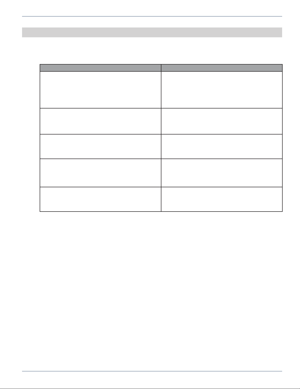
Condition Steps to Check
Power LED OFF (AC) 1. Check if Power Cable is Plugged in and Power Switch is
in ON position.
2. Verify AC Outlet is Functional and conrm fuse on the
AC feed is ne, replacing it if necessary.
3. Look for other signs of life in unit like running fan, LCD
display etc.
Power LED OFF (DC) 1. Verify DC Feed is active and fuse is intact on fuse panel.
2. Verify DC Feed is not reversed.
3. Look for other signs of life in unit like running fan, LCD
display etc.
Optical input LED is Amber or Red 1. Measure the optical input power to be certain it is within
the input operational range of the EDFA.
2. Inspect optical connectors to be sure they are clean and
not damaged.
No optical output or LED is Amber or Red 1. If there are no alarms and the output power is absent
or measured low, utilizing the Hand Held display or GUI
check the optical output power reading. If the status is
good it may indicate a faulty output connector. With the
EDFA disabled inspect the output connector.
Communication Issue with Unit 1. Please conrm setup is as described in the User
Interface document
2. If problem persists, please contact InnoTrans for further
help.
ChromaFlex CPA EDFA – Hardware Interface Manual 9-1
ATX Condential & Proprietary
Page 22

CHAPTER 9:
TROUBLESHOOTING THE CF-CPA EDFA MODULE
This page intentionally left blank.
9-2 ChromaFlex CPA EDFA – Hardware Interface Manual
ATX Condential & Proprietary
Page 23

SERVICE & SUPPORT
10. Service & Support
10.1 Contact ATX Networks
Please contact ATX Technical Support for assistance with any ATX products.
TECHNICAL SUPPORT
Tel: 289.204.7800 – press 1
SALES ASSISTANCE
Tel: 289.204.7800 – press 2
CHAPTER 10:
SERVICE & SUPPORT
FOR HELP WITH AN EXISTING ORDER
Tel: 289.204.7800 – press 3
10.2 Warranty Information
All of ATX Networks’ products have a 1-year warranty that covers manufacturer’s defects or failures.
ChromaFlex CPA EDFA – Hardware Interface Manual 10-1
ATX Condential & Proprietary
Page 24

ISO
REGISTERED
9001:15
© 2019 by ATX Networks Corp. and its affiliates (collectively “ATX Networks Corp.”).
All rights reserved. This material may not be published, broadcast, rewritten, or
redistributed. Information in this document is subject to change without notice.
Rev. 11/19 (ANW1242)
ATX Networks
Tel: 289.204.7800 | Toll-Free: 866.YOUR.ATX (866.968.7289) | [email protected]
www.atx.com
 Loading...