

Atwood Open Burner, Sealed burner Service Manual

Range
Service
Manual
2010

INTRODUCTION
The 2010 edition of the Atwood Range Service Manual is a resource created to help service technicians identify
Atwood product by serial number, diagnose service problems and efficiently and effectively process warranty
claims.
Each of the manuals within this series offers a general overview of the product as well as more specific product
information. For the range product within this manual, you will find model identification, sequence of operation,
part identification and troubleshooting guides, warranty procedures, flat rate schedules, and replacement part reference charts.
Due to the rapidly changing personal computer revolution, we have placed troubleshooting information in a variety
of places to make sure that the most accurate information is available. The best place to find the current information about Atwood products is our website: www.atwoodmobile.com. At our website brochures may be
downloaded, trouble shooting guides reviewed and the latest information bulletins can be read. In addition, all Atwood Authorized Service Centers are listed on our site, accessible via an easy-to-use search system.
Service for all Atwood products is handled our of our Elkhart Indiana location. Should you have any questions
regarding our products or the information contained in this manual simply dial our Toll Free # 1-800-546-8759
and select option 5 or call Service direct at, toll free, 1-866-869-3118. Be sure to have the Model and Serial
Numbers when you call.
Atwood Service Department
2

TABLE OF CONTENTS
INTRODUCTION……………………………………………………………….2
TABLE OF CONTENTS………………………………………………………..3
COOKING APPLIANCE TERMINOLOGY………………………………….4
MODEL NUMBER IDENTIFICATION……………………………………….5
GAS COMPONENT IDENTIFICATION PICTORALS…………………...6-7
SEQUENCE OF OPERATION-PRIOR TO MODEL 33………………...…...8
SEQUENCE OF OPERATION-MODELS 33, 34, 35, 20 & 21…………...…..9
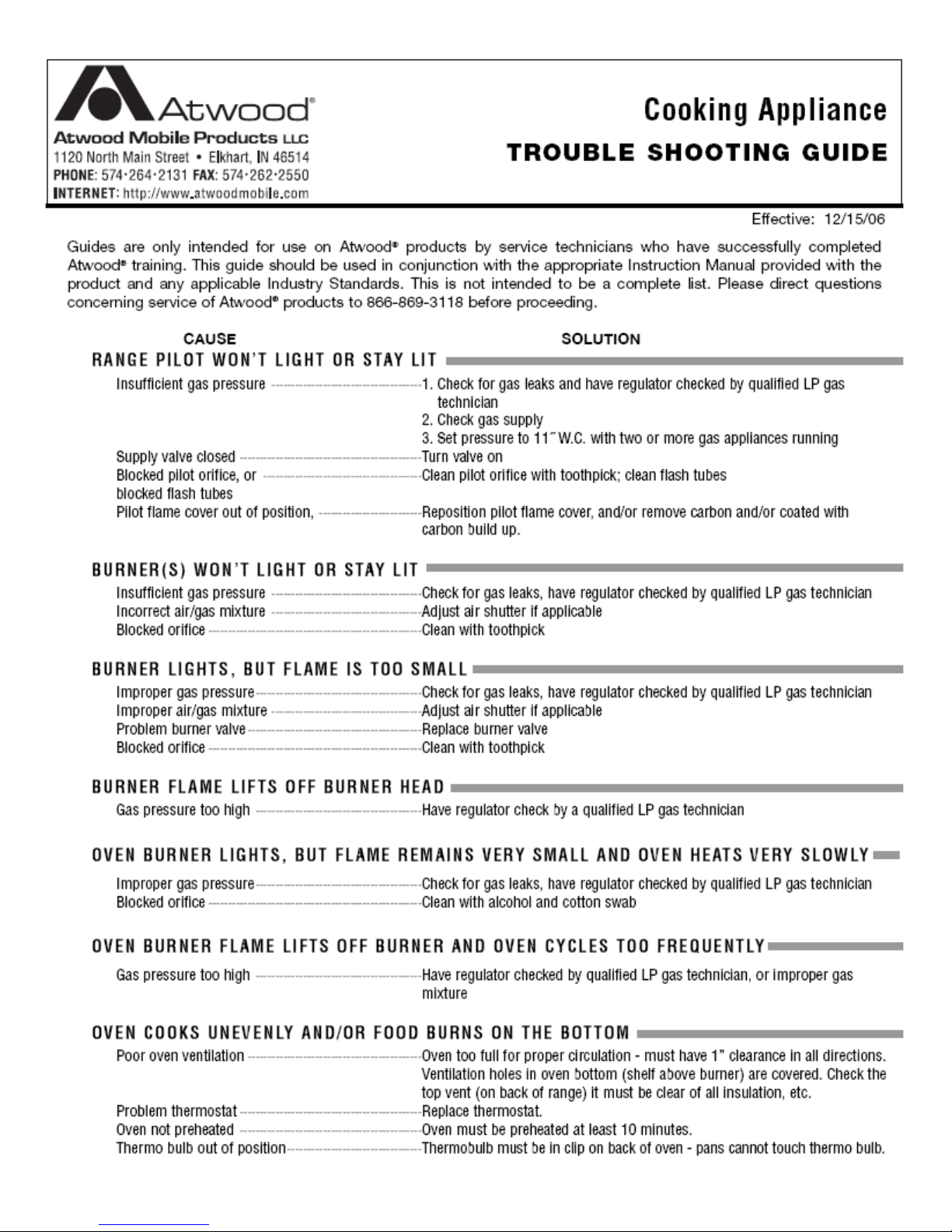
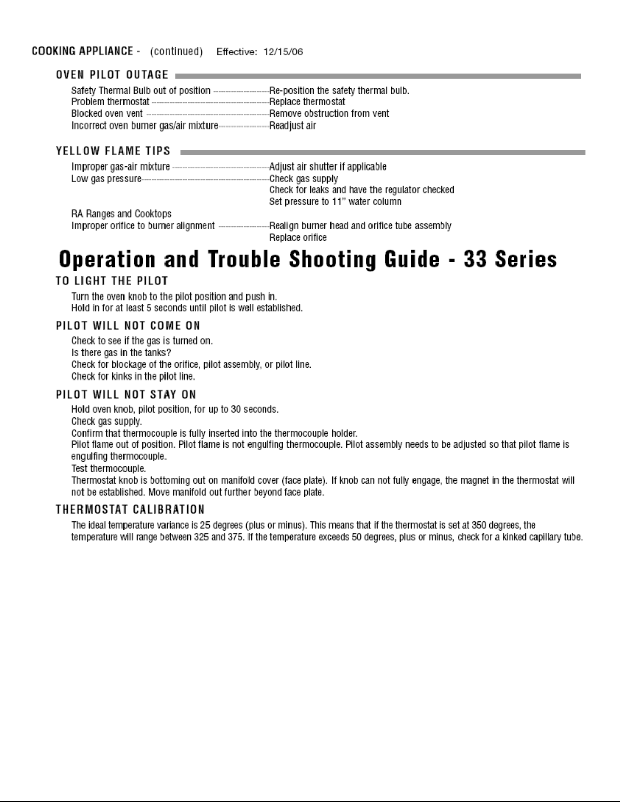
TROUBLE SHOOTING GUIDE………………………………………......10-11
INSTALLATION (Ranges & Slide-ins)
Cabinet and counter cut-out requirements…………………………….12
Recessed bi-fold cut-out requirement…………………………………..12
Electronic ignition schematic……………………………………………12
Range hood mounting information……………………………………..12
PART DIAGRAMS AND PART NUMBERS (Ranges & Slide-ins)
Model 33, RV/CV and RA/CA ……………………………………....13-14
Model 34, RV/CV and RA/CA………………………………………15-16
Model 20, RV/CV…………………………………………………….17-18
Model 35, RV/CV and RA/CA………………………………………19-20
Model 21, RV/CV…………………………………………………….21-22
Bi-Fold Covers and cut-out requirements……………………………..23
INSTALLATION (Drop-ins)
Cabinet and counter cut-out requirements…………………………….24
PART DIAGRAMS AND PART NUMBERS (Drop-ins)
Covers for DV Drop-in Models………………………………………….24
Model DV20 and DV30………………………………………………….25
WARRANTY……………………………………………………………………26
EXTENDED WARRANTY…………………………………………………….27
ATWOOD RETURN GOODS PROGRAM…………………………………..28
WARRANTY SERVICE REPORT……………………………………………29
FLAT RATE SCHEDULE……………………………………………………..30
INFORMATION NOTICES
3

ANSI
Certification Agency
(Canadian Standards Association)
4

4, 5
4, 5
5

6

Burner Systems International
• Mercury Free
Oven Thermostat Burner Valve Pilot Assembly
• Ranges with model numbers
R_ _ _ 34
• Lowest Temp on oven knob
is 300°F.
• Burner valve also used in
slide-in(s) with model number C_34 and C_20
Seven Universe
• Mercury Free
Oven Thermostat Burner Valve Pilot Assembly
• Ranges with model numbers
R_ _ _ 35 and R_ _ _ 21.
• Lowest temp on oven knob is
300°F.
• Burner valve also used in
slide-in(s) with model number C_35 and C_21.
Gas Regulator—Used in all Atwood Ranges, slide-ins and drop-ins.
Seven Universe
Regulates gas pressure to nominal 10” W.C.
Replaces all previous brands including Harper Wyman,
Maxitrol, Oara, and BSI.
7
8
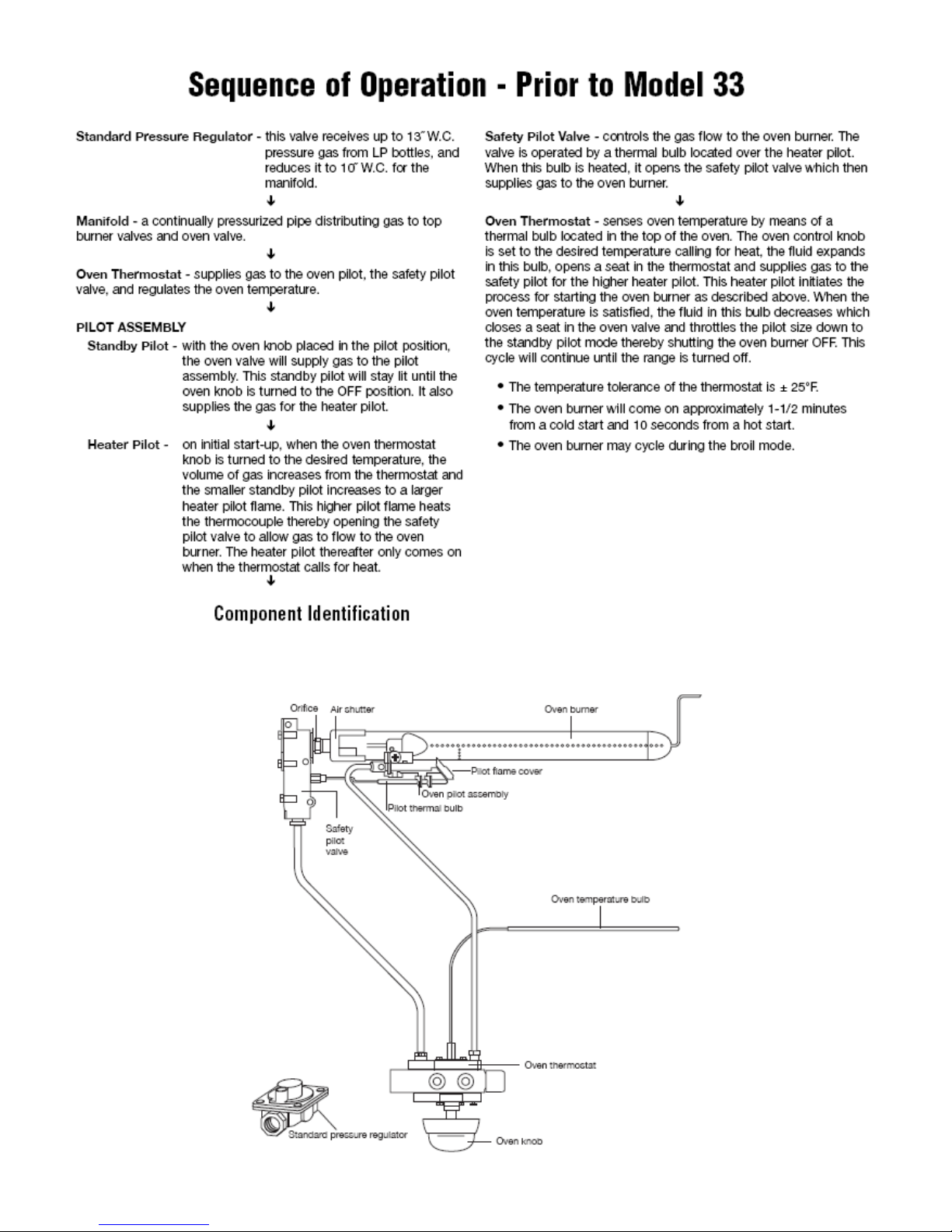
Sequence of Operation—Models 33, 34 and 35
Standard Pressure Regulator— This valve receives up to
13” W.C. gas pressure from regulated LP systems and reduces the pressure to 10” W.C. to the manifold.
Manifold—a continually pressurized pipe distributing gas
to top burner valves and oven thermostat.
Oven Thermostat— supplies gas to the oven pilot, and
main burner; regulates oven temperature.
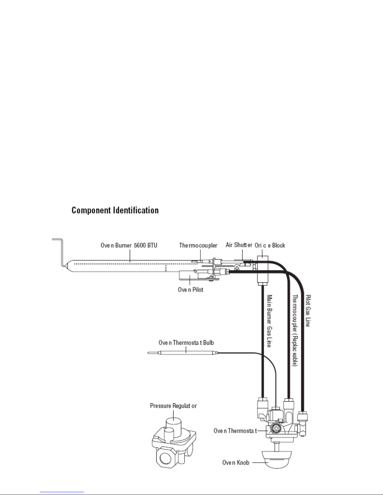
Pilot Assembly— consists of a thermocouple and a pilot
hood where gas passing through the orifice is directed toward the oven burner pilot holes. The user holds the magnet
in initially by pushing the knob in at the “pilot/push/hold”
rotation and manually lighting the pilot. After approximately 5 seconds, the thermocouple input will hold the
magnet in the open position and the user can release the
knob and adjust to the desired temperature.
Oven Thermostat - senses oven temperature by means of a
thermal bulb located in the upper rear of the oven. The oven
control knob is set to the desired temperature calling for
heat; the fluid expands in the bulb as the temperature rises,
moving the seat in the thermostat from full open to partial
open as the desired temperature is reached, thus maintaining
the set temperature. The gas is passed from the thermostat
to the orifice block in the main burner, entering the burner
and igniting from the pilot.
Oven Burner—The oven burner remains on once the ther-
mostat is turned on. The size of the flame changes to a high
or low flame by the thermostat as regulated by the user setting the knob and the thermostat bulb sensing a satisfied
oven temperature.
Note: The pilot gas line will remain open as long as the
pilot is lighted and the thermocouple senses flame. If the
pilot goes out, the magnet will drop out and shut off gas
flow to the pilot.
Note: Component
appearance may
vary from model to
model.
9
10
&
&
& &
UP
UP
UPUP
11
 Loading...