

Atwood AC-1361, AC-1511 Installation Operation & Maintenance
LITERATURE NUMBER MPD 15078
574-206-9713
•Installation •Operation •Maintenan
This air conditioner design has been certified by the Canadian
Standards Association for installation in recreation vehicles.
SERVICE CALLS & QUESTIONS
Location and phone numbers of qualified Service Centers can
be found at our website
866-869-3116 to locate a Service Center.
WARNING: It is important that this installation
manual is read and understood before
installation. The unit must be installed by a
qualified service technician. Failure to properly
install the unit or attempting to modify it in any
way can be extremely hazardous and may
result in property damage and personal injury
and will void the warranty.
http:/www.atwoodmobile.com
ce Effective 07/31/2013
or call
BEFORE INSTALLATION
Ensure
that the installation instructions have
properly read and
Installation must conform
regulations or, in the
Standard on Recreational Vehicles, NFPA 1192.
National Electrical Code NFPA
DO NOT
installation procedure.
This equipment must
refrigeration mechanic to maintain warranty
coverage.
If
please contact Atw
advice.
Atwood will not be held responsible for problems
relating to incorrect or improper installation
methods.
attempt
your installation varies
underst
to
ood.
to
Local wiring codes
absence
modify
only be serviced by a license
ood Mobile Pr
of
local codes,
70.
or
add components
from the method
oducts, LLC
been
and
the
and
to the
d
outlined
for specialt
y
GENERAL
Rooftop
for
Recreational
Air
Conditioner
Ducted Models
AC-1361 & AC-1511
INFORMATION
Vehicles
I. PURPOSE
This Atw
for installati
provide cooling
with AC1511 models.
-The
unit which is 86lbs (39Kg).
-The absolute minimum thickness
less than
-The
5 inches (125mm).
-Trimming
depending on
It
according
ood
AirCommand
on on
the roof of a recreational
with AC1361 models and cooling/heating
roof must be capable
1 inch (25mm).
maximum thickness
of the ductwork and/or bolts may be necessary
the roof thickness
is important
that the unit
to the
recommended guidelines.
air conditioning unit
vehicle
of supporting the weight
of the roof must
of the roof must
is installed properly
not exceed
is designed
to
of the
not be
and
II. ENSURING EFFECTIVE OPERATION
The effectiveness of the
s
everal factors
an Atwood
vehicle is
in all
walls and
(preferably double glazed) and
when closed. Other methods of
-Closing all doors, hatches, windows and blinds
-Position the
and protect
-Turning
-Ensuring
In
periods
to start the air conditioner earlier
improve its ab
e.g. size and heat load
unit
is installed Atw
well insulated
roof, that the wi
vehicle so
the wi
off
appliances
the
vehicle is parked
of extreme
ility
air conditioner is dependent
of the
vehicle. When
ood assumes
with 1 inch (25mm) foam minimum
ndows are
the roof vents are
reducing heat load
if
porch is used,
ndows
from direct
that might
high temperature it
to
cope
with the expected high heat
radiation.
increase
in
a shaded position.
in the
that the
of moderate size
it will
face
the heat
is
morning
on
airtight
include:
the sun
load
recommended
to greatly
III. CONDENSATION
In areas
cause “sweatin
humid warm air contacts
this
-Closing all doors, hatches, windows and blinds
ingress
c
higher airflow and reduce
c
of
high humidity, the
g” or condensation in parts of the unit
occurs please ensure
of
warm humid
Avoid running
onditions. Running
ondensation form.
the
humid air
the
colder air discharge system. If
the following:
air
inside fan on LOW
the
fan on HI fan speed
the tendency to have
within the
or
AUTO
will result
RV
will
as
to limit the
in such
in
load.
the
AC IOM DUCTED 7/31/2013 rev 3 1
1
2 3 5
7 9 4
6
8
Installation Guide – Ducted Atwood Air Command
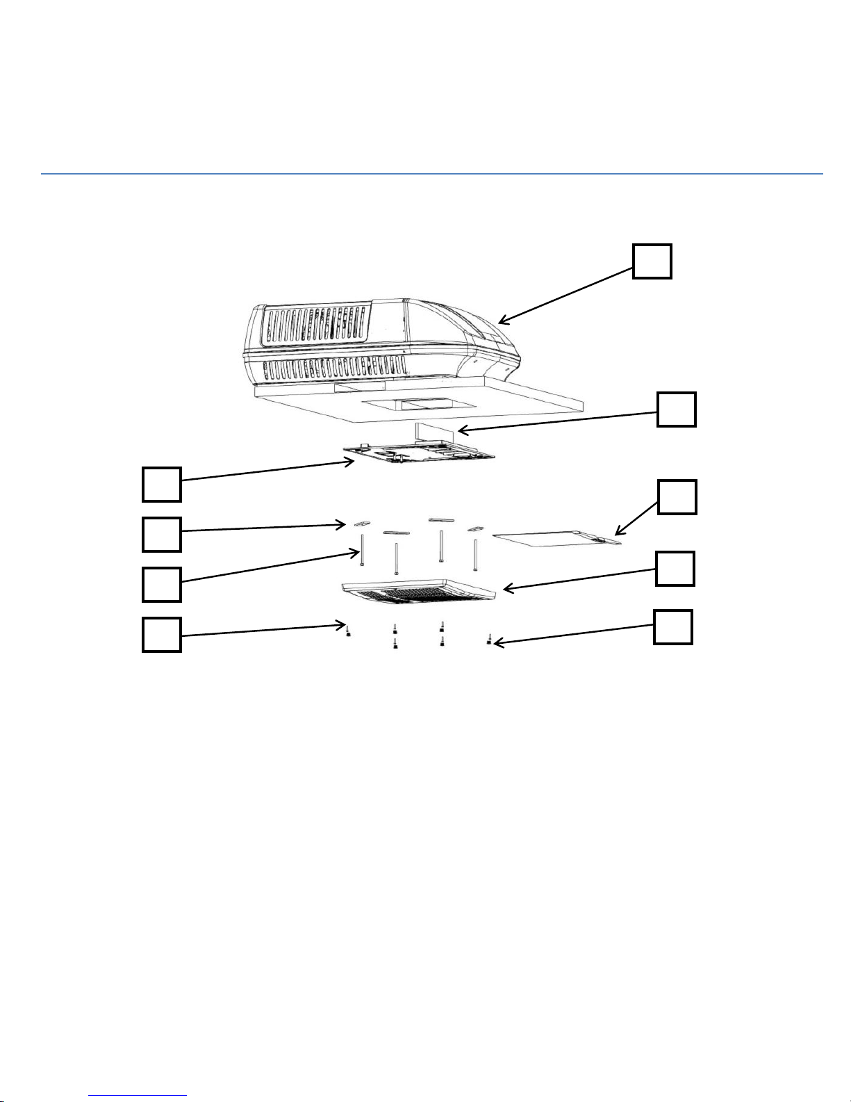
Exploded view of Installation Parts
1. Air Command Cormorant Rooftop Air Conditioner
2. Polystyrene baffle x 1
3. Plenum deck assembly x 1
4. Hold down bars x 4
5. Filter x 1
6. Hold down bolts M8 x 4
7. Plenum fascia x 1
8. Screw, button head 20mm x 6
9. Cover plugs x 6
10. Control Pad & Extension cable (not shown)
11. Roof sealing gasket (not shown)
AC IOM DUCTED 7/31/2013 rev 3 2
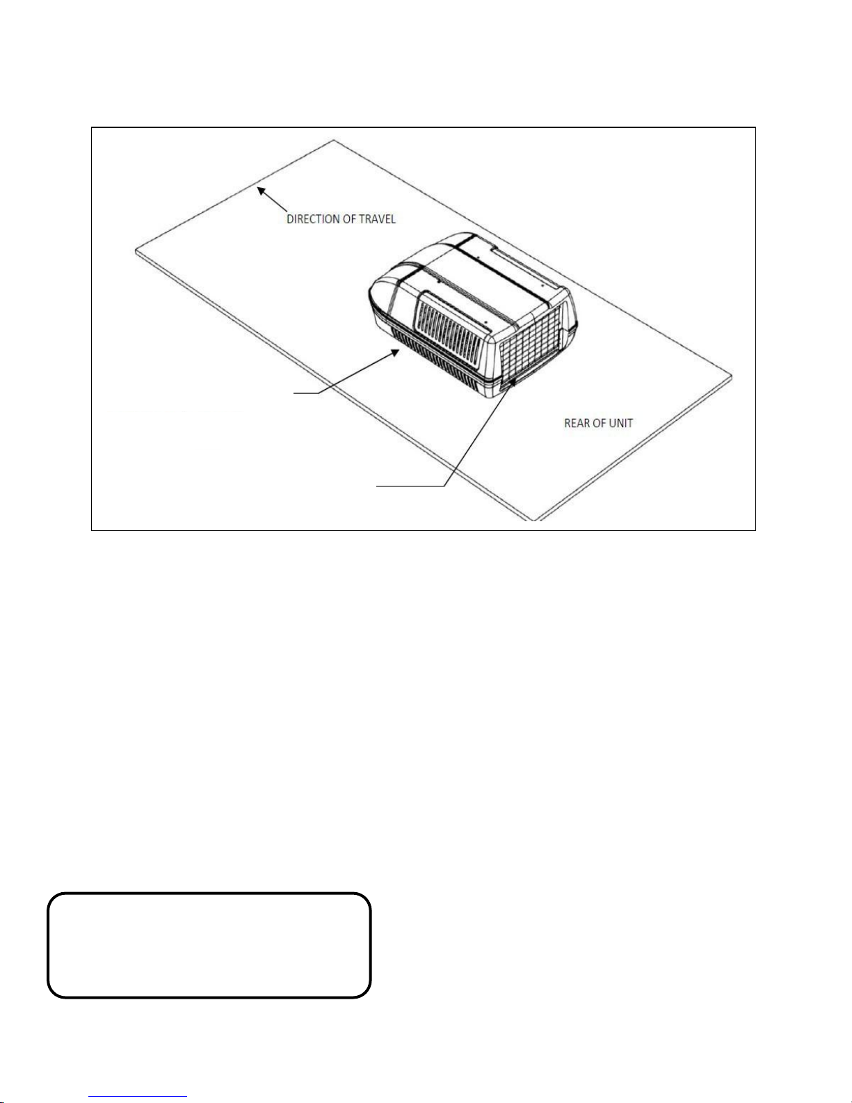
Minimum 1 inch clearance from
side grills to any obstruction.
Minimum 8 inch clearance from
45 degree face.
INSTALLATION POSITION
rear grills to any vertical face.
Minimum 4 inch clearance to any
Unit Installation
Before beginning, mark
considering
-
The air conditioner should be situated as centrally
possible on
-
The
travel;
damage
- If the
high heat load (see General Operating Information
section regarding expectations about insulation etc
Atwood
effectively.
-
When considering
to
check
vehicle.
-
Avoid an installation position
cupboard
discharge air
the
following
the
vehicle,
front of the unit MUST
failure
to follow this instruction
to the
condenser fans.
vehicle is over 23’
would recommend
for
clearance around
or light fitting could
flow from the plenum.
out the position
important requirements:
to
ensure
face
in length,
2 or
the installation position remember
the
where a bulkhead,
interfere
of the unit
even
air distribution.
the direction
will result
or
has
more units to cool
plenum inside
an
unusually
with the
of
CAUTION
It is important that the unit is never more
than
5⁰ from the horizontal and the rear of
the unit should never be higher than the
front.
in
the
as
.),
- Contact Atwood
if
your installation differs significantly.
ASSESS ROOF STRENGTH
-
The
roof
s
upport
the weight
that will
manufacturer to
doubt
- If the roof
roof then use
your
-
The square hole
minimum 3/4 inch
withstand the compressi
that
access
- Longitudinals MUST
to transfer
cause
consider
RV manufacturer
air
is not
for wiring.
members
does
load
MUST
of the unit
“pooling” of
confirm
the
use
not
the roof
in the roof (14” x 14”)
square timber
drawn
(see Fig
be strong enough to
water around
the
max
of an externa
have an existing hole
hole as a guide
for the best met
on
of the installation bolts.
from the roof cavity
be fixed securely
3).
86
lbs
(39kg)
without
the unit. Contact
load the roof
l “H” frame.
one must be cut. Cut
to cut through
hod
to cut through
MUST
to
provide a structure strong enough
(Fig
3 &
to the transverse roof
any
is able
to
handle.
the
ceiling. Contact
be boxed up
This is also
4). Remember
roof deflection
your
RV
If in
any
from the
the roof.
with
to ensure
to
leave
members
to
AC IOM DUCTED 7/31/2013 rev 3 3

.79 MIN
WARNING
There may be electrical wiring located between
the roof and ceiling. Ensure that power is
properly disconnected at the supply (mains
and/or battery). Failure to do so may result in
personal injury or death
TIP:
Always use crawl boards across
damage
POSITION UNIT ON ROOF
-
Remove
- Position the unit
the
of the
the
TIP:
hole while
of the unit.
the
air conditioner
over
the gasket so
square hole
square
air conditioner (Fig
Have one person inside
in the RV roof
hole
the other
underneath
6).
is on
from the carton.
the RV
the roof adjusting the position
the roof to
that the
line up
with the
looking through
avoid
corners
corners
of
the
Fig 6- Gently set the unit over the roof gasket..
WARNING
The unit weights approximately 86 lbs (39kg).
Ensure a two person lift or use a mechanical
hoist to avoid the risk of injury.
-Do NOT slide the unit on the roof. This may
damage the gasket and result in leaks.
- Position the unit so that the four M8
mounting holes will line up with the four
corners of the square roof hole (Fig 7).
Fig 7- Shows the view from under the roof.
AC IOM DUCTED 7/31/2013 rev 3 4
Roof Thickness Inch (mm) –
Include ‘H’
frame if
Duct length
required – Inch
(mm)
Hold down bolt
length required
– Inch (mm)
4.92 (125)
5.71 (145) as
supplied
As supplied
3.94 (100)
4.72 (120) - Cut
.98 (25)
As supplied
3.15 (80)
3.94 (100) –
Cut1.77 (45)
As supplied
2.36 (60)
3.15 (80) – Cut
2.56 (65)
Cut 1.97 (50)
1.57 (40)
2.36 (60) – Cut
3.35 (85)
Cut 2.76 (70)
1.0 (25)
(absolute
1.57 (40) – Cut
3.94 (100)
Cut 3.35 (85)
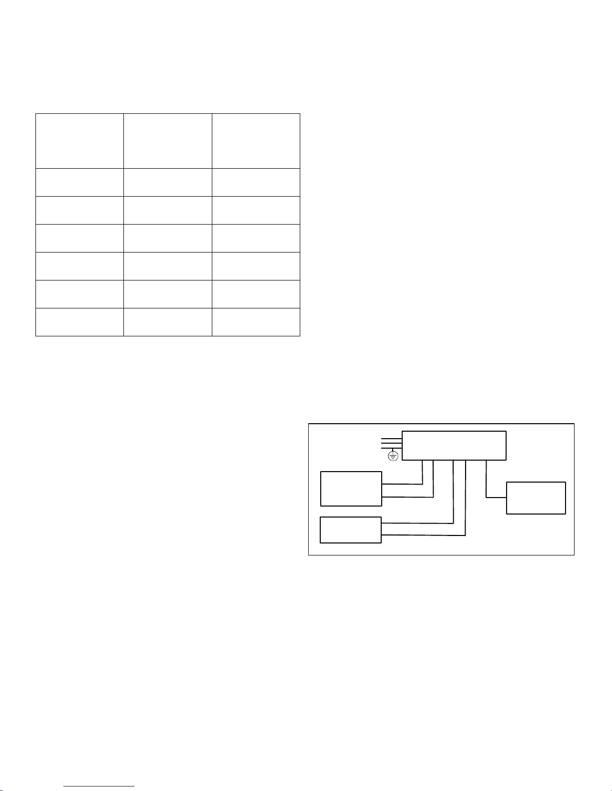
Interconnection diagram for AC models
RED
BLACK
BLUE
BLUE
RED
+12v
-12v RET
ROOFTOP AC UNIT
WALLMOUNTED
THERMOSTAT
+12V SUPPLY
(CONVERTER)
FURNACE
4-WIRE CABLE
115 VAC
DETERMINE ROOF THICKNESS
-Measure the roof thickness and consult the table on next
page to check if adjustments to the hold down bolt and duct
length are required.
INTERCONNECTION CABLES
Three sets of interconnecting cables must be installed before
installing the rooftop unit. The three sets of cables are for
+12V power, connecting to the furnace, and a
communication cable between the wall mounted thermostat
and the rooftop unit.
+12V Power Connections
Customer provided +12V to the red wire in the
rooftop unit
Customer provided -12V return to the black wire in
rooftop unit
Furnace Connections
Furnace output wire to one of the blue wires in the
rooftop unit
Furnace input wire to the other blue wire in the
rooftop unit
These two connections are interchangeable since
the blue wires are connected to a relay contact in
the rooftop unit
Communication Connection
This is a 4-wire cable (supplied by Atwood) which
connects the wall mounted thermostat to the rooftop
unit.
with wall-mounted thermostat
AC IOM DUCTED 7/31/2013 rev 3 5

CONNECT AC ELECTRICAL SUPPLY
Wire Range
AWG
Order
No.
Optional
Hand Tool
Optional Bench
M
ount Tool
Optional Bench
Arbor Press
Housing
Color
12-14 19045-1000
(COC-1)
19285-0074 N/A
64006-0200
White
Installation must conform
on Recreational Vehicles, NFPA 1192.
- Connect AC
- Note:
power supply
Brown wire from rooftop
Blue wire from rooftop unit
Yellow/Green wire from rooftop unit to Green wire from customer – Ground
to
local wiring codes and regulations
and National Electrical
to wire
leads
from unit
unit to Black or Red wire from customer – AC Hot
to White wire
from customer
or, in the
Code NFPA
– AC
Common
absence
70.
of local
codes,
the Standar
d
WARNING
Ensure that power is properly disconnected at the supply (mains and/or battery).
Failure to do so may result in damage to the unit and personal injury or death.
AC connections can be made following the COC-1 procedure below using the connector: Atwood PN 15024.
COC-1 Self Contained Power
For 2 Wire Cable With Ground Applications
The 2-circuit-with-ground connectors will splice non-metallic-sheathed cable in the following wire ranges and types:
Self Contained Connector
2 Circuit with ground for Solid Wire
Referenc
e Information
UL File Number: E182087,
CSA File Number: LR18689-C53
NEC Article: 550, 551, and 545
HUD Section: 3280.801
Current:
20A,Voltage:
-
300V
Connector Installation Instructions
FIG. 2
AC IOM DUCTED 7/31/2013 rev 3 6
 Loading...