

Atwood 8516, 8516-LD, 8520-LD, 9525-LD, 9531-LD Technical Lnstallation Manual
...
/iltAtwood'
Atwood
Mobile Products
LLc
1120
North Main
Street
.
Elkhart,
lN 46514
USA
:
800-546-8759
Canada & USA : 800-825-4328
lnternet:
http://www.atwoodmobile.com
/A\
(w)
\ \.--
--z<
// TM
\qSTEyy/
Literature
number
30090
hydro flamerM
8500-lV Series Furnaces
Models
8516,
8520, 8525,
8531, 8535
8516-LD, 8520-LD,
9525-LD, 9531-LD,
8535-LD
1
522, 2334, 1
522-LD, 2334-LD
Technical
lnstallation
Manual
English,
Frangais
(et
Canada)
This
instruction
manual is
for
use by an authorized
service
technician
to install
an
Atwood
-
hydro flamerM
furnace.
Should
you
require
further
information,
contact
your
dealer or nearest
Atwood
Mobile
Products
Service
Center.
This furnace
design
has
been
certified
for
installation in
recreation
vehicles
as a MSP
Category lll furnace. Follow
this
installation
instruction
to
insure
safe operation
of the furnace.
Failure
to install
furnace
according to this installation instruction
nullifies
the furnace
warranty.
Effective
10/10
A
wlnu*c
Avoid
possible
injury
or death
lmproper installation,
adjustment,
alteration, service
or
maintenance
can cause
property
damage,
personal
injury
or
loss
of life. Refer
to the
installation
instructions
and/or
owners
manual
provided
with
this appliance. lnstallation
and service must
be
performed
by a
qualified
installer,
service agency
or
the
gas
supplier.
INDEX
SPECIF|CAT|ONS.
...........2
MODELS
..,.,,.,,.2
OIMENSIONS
,,,,.2
WEIGHT
,,,,,,.,,2
MINIMUMCLEARANCETOCOMBUSTIBLES:
...
.....2
INSTALLATIONANDSAFETYCODES
,,....,2
GENERAL FURNACE
LOCATION
.,.,.,..,.,2
DOORSIDEWALLCUTOUT
.........3
DOORINSTALLATION.
.....3
LD VENT
SIDE WALL
CUTOUT
LD
VENT INSTALLATION
4
4
VERTICAL INSTALLATION
CAULKING AREAS
...,.4
DUCTING
OPTIONS
...,.,,.,4
REQUIREDMINIMUMDISCHARGE,....,...,,4
FLEXIBLE DUCTING
SYSTEMS
......5
HARD DUCTING
FLOOR
SYSTEMS
... ... ...5
HORIZONTALORVERTICALDISCHARGE
...........5
EXTENSTONBOXDISCHARGE...
..........5
FLEXADAPTER
PLATE
.....5
PROPANE
GAS
CONNECTION
.... ..6
ELECTRICALCONNECT|ONS...
...........6
CONDUCTORSIZINGTABLE
..,....,6
POWERSUPPLY
.....6
THERMOSTATINSTALLATION.....
.........6
OPERATING INSTRUCTIONS
..,
.,, ,,7
To
Shut
Down
.
.....
..7
SYSTEM CHECKS
......,.,..7
PROPANEGASPRESSURETEST
...,.,,.,,,7
STATIC
PBESSURETEST..
..
, ,.,...7
IGNITIONCONTROLDIAGNOSTICCODES
......,.,.7
STANDARD3TRIES
FOR IGNITION
CONTROLS
, ,,, ,,7
2-STAGE
3TRIES FOR
IGNITION
CONTROLS
, , . . . . . .7
WIRING DIAGRAMS
.. .......9
Bs-IVWIRING&
LADDER DIAGRAM
.........9
85-IV-LDWIRING&LADDER
DIAGRAM
......9
1522,2334LDWIRING&LADDERDIAGRAM
.. .,..10
1522,2334 WIRING
& LADDER DIAGRAM
...... ....10
Parts Drawing
....
..........11
TO THE
INSTALLEH:
.TO
THE
CONSUMER:
LEAVE THIS
MANUAL WITH
THE
APPLIANCE.
RETAIN
THIS MANUAL
FOR
FUTURE REFERENCE.
SAFETY
ALERT
SYMBOLS
Safety
Symbols alerting
you
to
potential
personal
safety
hazards
obey
all safety
messages
following
these
symbols
A
wanuxc
Avoid
possible
injury
or
death
A
caunoru
Avoid
possible
injury
and/or
propertv
damaoe
A
wanumc
FIRE
OR EXPLOSION
lf the information
in
this manual is not
followed
exactly, a
fire
or explosion may
result
causing
property
damage,
personal
injury
or loss
of
life.
FOR YOUR
SAFETY
WHAT
TO DO IF YOU
SMELL GAS:
.
Extinguish
any open flame.
r
Evacuate
all
persons
from
the
vehicle.
.
Shut off the
gas
supply
at the
gas
container
or
source.
.
Do not
touch
any electrical switch,
or use any
phone
or
radio in
the vehicle.
.
Do not
start the
vehicle's
engine or
electric
generator.
o
Contact
the nearest
gas
supplier
or
qualified
service
technician for repairs.
.
lf
you
cannot
reach
a
gas
supplier
or
qualified
service
technician, contact
the
nearest
fire
department.
.
Do
not
turn on the
gas
supply until
the
gas
leak(s)
has
been
repaired.
lnstallation
and service must
be
performed
by a
qualified
Service Technician,
Service Center
or
gas
supplier. Parts List
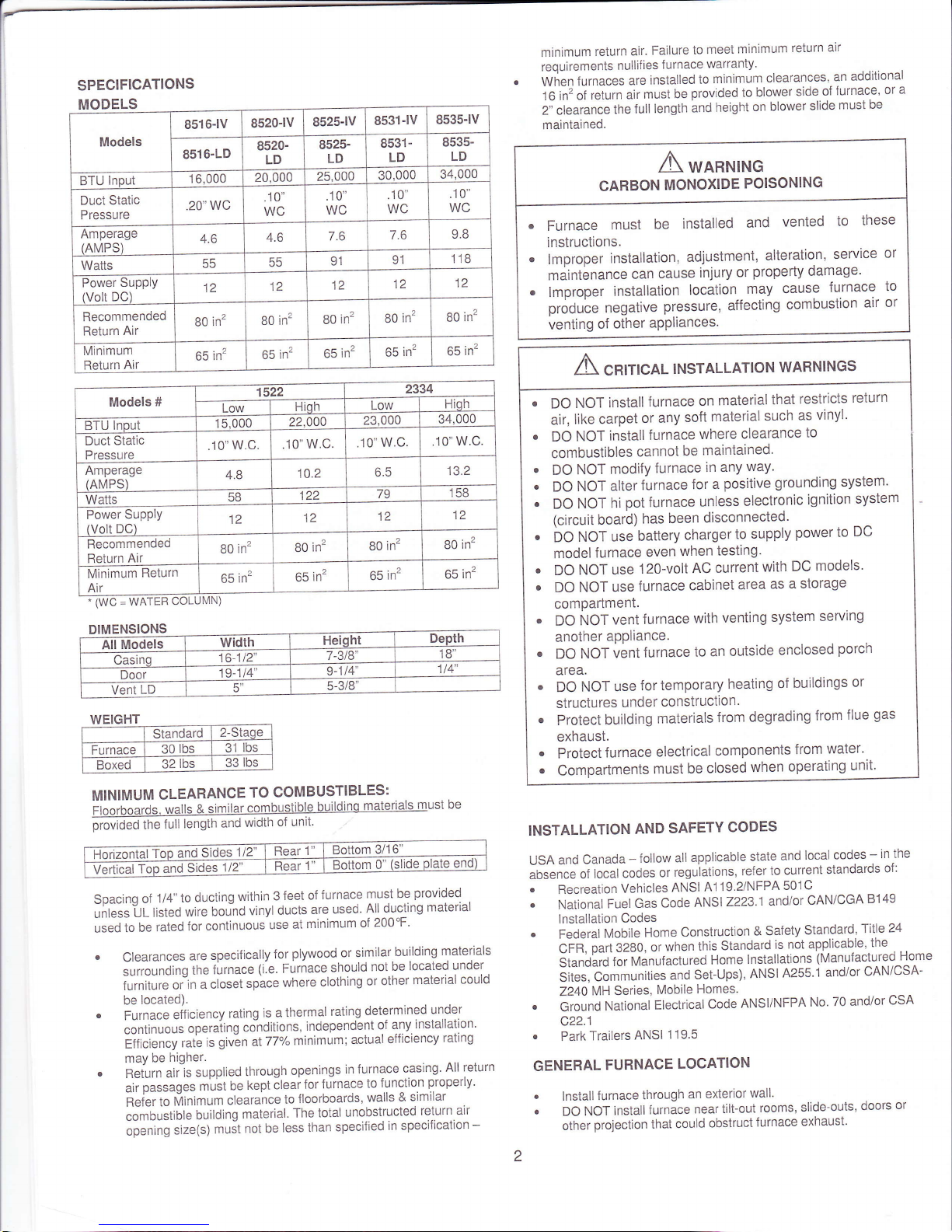
Models
8516-lv
8520-lv
8525-lv
8531-lV
8s35-lV
8516-LD
8520-
LD
8s25-
LD
8531-
LD
8535-
LD
BTU lnout
16,000
20.000
25,000
30,000
34,000
Duct Static
Pressure
20'wc
.10"
WC
.10"
WC
.10"
WC
.10"
WC
Amperage
(AMPS)
4.6
4.6
7.6
7.6
9.8
Watts
55
55
91
91
118
Power
Supply
(Volt
DC)
12
12
12
12
12
Recommended
Return Air
80
in2
80
in2
80
in2
80
in2
80
in2
Minimum
Return
Air
65
in2
65
in2
65
in2
65
in2
65 in2
SPECIFICATIONS
MODELS
(wc
DIMENSIONS
WEIGHT
Standard
2-Staqe
Furnace
30
lbs
31
lbs
Boxed
32
lbs
33
lbs
MINIMUM
CLEARANCE
TO
COMBUSTIBLES:
ii;o;b;;rds.
walls
&
similar
combustible
buildino
materials
must
be
prwiOeO
tne
full
length
and
width
of unit'
Soacinq
of
1/4" to
ducting
within
3
ieet
of
furnace
must
be
provided
.
J[[.i
LL
ri.t.d
wire
boLind
vinyl
ducts
are
used
All
ducting
material
,..Jt
O"
rated
ior
continuous
use
at
minimum
of
200"F'
.
Clearances
are
specilically
for
plywood
or similar
building
materials
sriiornOing
the
furnace
(i.e. Furnace
should
not
be
located
under
furniture
oiin
a closet
space
where
clothing
or other
material
could
be
located).
.
Furnace
"ifi.i.n.y
rating
is a thermal
rating
determined
under
continuous
operaiing
co-nditions,
independent
of
any
installation.
Etti.i.n.v
rate
ls
giv-en
at
77%
minimum;
actual
elficiency
rating
may be
higher.
.
Reiurn
airls
supplied
through
openings
in
furnace
casing.
All
return
"ii
p".*g".
,Lit
o"
kept
cleai
for
furnace
to
function
properly'
n"t",
to
frini.r,
clearance
to
floorboards,
walls
&
similar
combustible
building
material'
The
total
unobstructed
return
air
opening
size(s)
muit
not be
less
than
specified
in
specification
-
minimum
return
air.
Failure
to
meet
minimum
return
alr
requirements
nullif
ies f urnace
warranty.
When
frrnuces
are
installed
to
minimum
clearances,
an
additional
t
6
in'
of
return
air
must
be
provided to
blower
side
of
furnace'
or
a
2i ciearance
the
full
length
and
height
on
blower
slide
must be
maintained.
INSTALLATION
AND
SAFETY
CODES
USA
and
Canada
-
follow
all
applicable
state
and
local
codes
-
in the
absence
of
local
codes
or
reguiations,
refer
to
current
standards
o1:
.
Recreation
Vehicles
ANSI
A1
19.2/NFPA
501C
.
National
Fuel
Gas
Code
ANSI
2223'1
andlor
CAN/CGA
B149
lnstallation
Codes
Federal
Mobile
Home
Construction
& Safety
Standard'
fille
24
CFn,
patt
3280,
or
when
this
Standard
is
not applicable'
the
Siunblio
ror.
Manufactured
Home
lnstallations
(Manufactured
Home
SiG.,
C".rr.ities
and
Set-ups),
ANSI
A255'1
and/or
CAN/CSA-
Z24O
MH Series,
Mobile
Homes.
Ground
National
Electrical
Code
ANSI/NFPA
No'
70 and/or
CSA
c22.1
Park
Trailers
ANSI
119.5
UMN)
GENERAL
FURNACE
LOCATION
a
a
lnstall
furnace
through
an exterior
wall'
DO
NOT
install
furnace
near
iilt-out
rooms,
slide-outs'
doors
or
other
projection
that
could
obstruct
furnace
exhaust'
A
wannrnc
CARBON
MONOXIDE
POISONING
.
Furnace
must
be
installed
and
vented
to
these
lnstructions.
.
lmproper
installation,
adjustment,
alteration,
service
or
maintenance
can
cause
injury
or
property damage'
.
lmproper
installation
location
may
cause
furnace
to
produce
negative
pressure,
affecting
combustion
air
or
venting
of
other
aPPliances.
Models #
't522
2334
Low
Hiql'
Low
Hiqh
BTU
lnput
15 000
22,000
23,000
34,000
Duct
Static
Pressure
.10'w.c
.10"
w.c.
.10'w.c.
.10"
w.c.
Amperage
(AMPS)
4.8
10.2
6.5
13.2
Watts
58
122
ao
158
Power
Supply
(Volt
DC)
12
12
12
12
Recommended
Return
Air
80
in2
80
in2
80
in2
B0
in2
Minimum
Return
Air
65 in2
65 in2
65
in2
65
in2
A
"*,r,"oL
'NSTALLATI.N
*ARN'NGS
a
a
a
DO
NOT
install
furnace
on
material
that
restricts
return
air,
like carpet
or any
soft
material
such
as
vinyl'
DO
NOT
install
furnace
where
clearance
to
combustibles
cannot
be
maintained.
DO
NOT
modifY
furnace
in anY
waY'
DO
NOT
alter
furnace
for
a
positive
grounding system'
DO
NOT
hi
pot
furnace
unless
electronic
ignition
system
(circuit board)
has been
disconnected'
bO
ruOr
use
battery
charger
to
supply
power
to
DC
model
furnace
even
when
testing.
DO
NOT
use
12O-volt
AC
current
with
DC
models'
DO
NOT
use
furnace
cabinet
area
as
a storage
compartment
DO
NOT
vent
furnace
with
venting
system
servlng
another
appliance.
DO
NOT
vent
furnace
to
an
outside
enclosed
porch
area.
DO
NOT use
for temporary
heating
of
buildings
or
structures
under
construction.
Protect
building
materials
from
degrading
from
flue
gas
exhaust.
Protect
furnace
electrical
components
from
water'
a
a
a
a
Compartments
must
be
closed
when
operating
unit'
All
Models
widrh
Height
Depth
/lac
16-112"
7-318"
'18',
Door
19-114"
9-114
114"
Vent
LD
5-3/8"
Horizontal
ToP
and
Sides
1/2"
Rear
1
Bottom
3/16"
Vertical
Top
and
Sides
1/2"
Rear
1
Bottom
0"
(slide
plate
end)
Locate furnace near midpoint of coach
for
single
furnace
applications.
lnstallation must
provide
accessibility
if any repairs are
necessary
to
the furnace. Failure
to
meet
this
requirement will create additional
labor
costs that
will
be the
responsibility
of the
installer.
DO NOT install vent in
areas
where
projection
or door openings
come
within
6" of
vent
tube opening.
DO NOT
install furnace
in
an area
where wires,
pipes
or other
ob.jects will interfere
with installation
or operation
of furnace.
DO
NOT install furnace on material that
restricts return
air, such as
directly
on carpet,
or soft material
(like
vinyl). lf
you
must install
furnace
on carpet or soft
material, install furnace on
cleats,
or on a
wood
or metal
panel
extending the
full width and depth of furnace
plus
minimum
clearance
to combustibles.
DO NOT
use
peiroleum
or cilrus
type cleaner on
plastic parts,
as
damage may
occur.
A
*o*wrttc
CARBON
MONOXIDE POISONING
Properly
seal door/vent assembly to
prevent
carbon
monoxide from
entering coach.
o
DO
NOT draw combustion air
from living
area.
.
DO NOT vent
exhaust air
into
the
living
area or an
enclosed
porch.
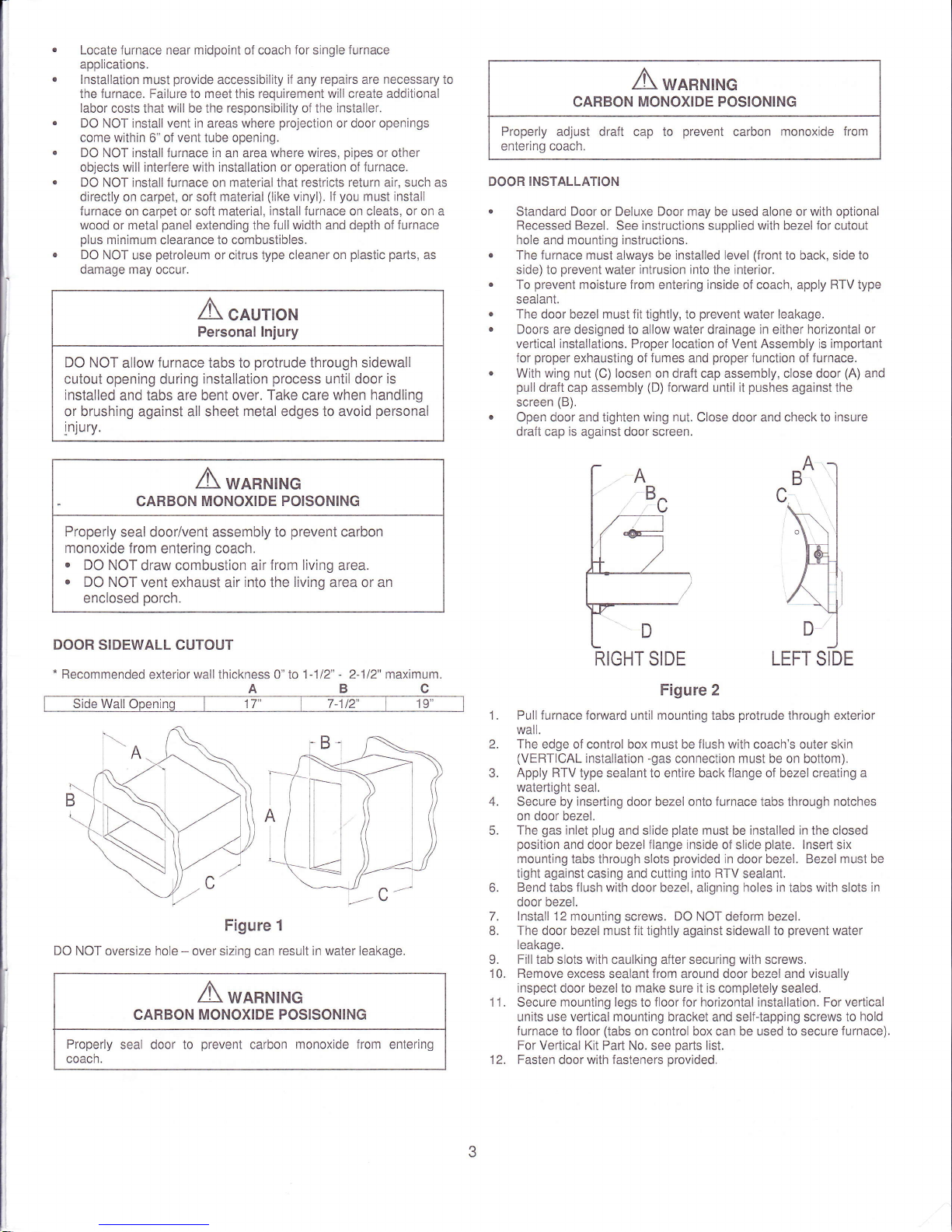
DOOR
SIDEWALL CUTOUT
*
Recommended
exterior
wall
thickness
0" 1o 1-112"
-
2-112'maximum.
ABC
Figure 1
DO NOT
oversize
hole
-
over sizing can
result in water leakage.
A
*o*,u'rc
CARBON
MONOXIDE POSISONING
Properly
seal door to
prevent
carbon
monoxide
from entering
coach.
A
wlnu*c
CARBON
MONOXIDE POSIONING
Properly
adjust draft cap to
prevent
carbon
monoxide from
entering
coach.
DOOR
INSTALLATION
.
Standard Door
or
Deluxe Door may
be used alone or
with
optional
Recessed Bezel.
See
instructions
supplied
with
bezel
for cutout
hole
and mounting instructions.
.
The
furnace
must always be
installed level
(front
to back, side to
side) to
prevent
water intrusion lnto the interlor.
.
To
prevent
moisture f rom
entering
inside
of coach, apply
RTV type
sealant.
.
The
door bezel
must fit
tightly, to
prevent
water leakage.
o
Doors are designed
to
allow water drainage in either horizontal or
vertical installations. Proper location
of
Vent Assembly is important
for
proper
exhausting of
fumes
and
proper
function
of
furnace.
.
With
wing
nut
(C)
loosen on draft cap assembly, close door
(A)
and
pull
draft cap
assembly
(D)
fonntard until it
pushes
against the
screen
(B).
.
Open door and tighten
wing nut.
Close door and check to
insure
draft cap
is
against door screen.
RIGHT
SIDE
LEFT
SIDE
Figure 2
Pull furnace
forward until mounting tabs
protrude
through exterior
wall.
The
edge of control box must be flush with
coach's outer
skin
(VERTICAL
installation
-gas
connection must be on bottom).
Apply RTV
type sealant to entire back flange of bezel creating a
watertight
seal.
Secure by
inserting
door bezel onto
furnace
tabs through
notches
on door bezel.
The
gas
inlet
plug
and slide
plate
must
be installed in the closed
position
and door bezel
flange inside
of slide
plate.
lnsert six
mounting tabs lhrough slots
provided
in
door bezel.
Bezel must be
tight against casing and cuiting
into RTV
sealant.
Bend
tabs
flush with
door bezel, aligning holes
in
tabs
with
slots
in
door
bezel.
lnstall 12
mounting screws. DO NOT deform bezel.
The door bezel must fit tightly against sidewall to
prevent
water
leakage.
Fill tab slots with
caulking
after
securing
wlth
screws.
Remove
excess sealant
from
around door bezel and
visually
inspect
door bezel to make sure
it
is completely sealed.
Secure mounting legs to floor for horizontal installation. For
vertical
units use
vertical mounting
bracket and self{apping screws to
hold
furnace to floor
(tabs
on
control
box can be used to secure
furnace).
For Vertical Kit Part No.
see
parts
list.
Fasten
door with fasteners
provided.
t.
2.
4.
5.
b.
7.
8.
o
10.
11.
CAUTION
Personal lnjury
DO NOT
allow furnace tabs to
protrude
through sidewall
cutout
opening during
installation
process
until door
is
installed
and tabs are bent over.
Take
care
when handling
or brushing against all sheet
metal
edges to avoid
personal
!njury.
RIGHT
SIDE
12.

LD VENT
SIDE
WALL
CUTOUT
c_r
C
a':
Figure
3
B
Side
Wall
Cutout
2-3t8"
1-1
12"
J- llz
Diameter
hole
*
Recommended
wall
thickness
0" 1o
2-112"
OOfrf
Ot
oversize
hole
-
over
sizing
can
result
in
water
leakage'
LD VENT
INSTALLATION
VERTICAL
INSTALLATION
CAULKING
AREAS
I
,/
Figure
4
You
Must
Caulk-
all
areas
shown'
.
Around
entire
red
gas inlet
plug
"C"'
.
Around
entire
black
stiJe
plateldges
were
it mates
with
sheet
metal
D
A
B
t-
L
a
"8".
Alound
entire
gas line
where
it
enters
gas inlet
plug
"D"
ni..g
*"fJ.O
ioints
"A'
of
two
bottom
corners
of sheet
metal
casing
and
irere
door
tlange
covers
slide
plate'
DUCTING
OPTIONS
REQUIRED
MINIMUM
DISCHARGE
Models
8516,8520
8s25,
8s31
otretr
1522
2334
All
Models
using
toP
or
bottom
discharge
oPtions
All vertical
installations
Required
Discharge
Area
24 in'
36
in2
48
inz
36
in2
48
in2
48
in2
48
in2
--a--
i
A
B-
A
1.
2.
J.
4.
tr
6.
Locate
vent
hole
cutout
as
called
out
oiirii-rlz"
dlameter
hole
through
sidewall
of
coach'
Remove
vent
and
vent
ring
from
furnace'
l;;;;iir;;;.lrom
backsi-de
of
wall,
lining
up
hole
in
wall
with
hole
for
vent
in
furnace.
ippty
seatant
to
back
of
vent
ring
and
vent
cap
base'
inllu'ir
u"nt
assembly
with
HOT
it top
on
horizontal
installations
and
iloT
".ligr,t;ide
for
vertical
installations
Vent
ring
must
slip
i.Jil"
."rinrittn
air
intake
tube'
Secure
to
wall
with
four
(4)
screws
not
Provided.
ili,.i*."rrlUfy
must
maintain
minimum
overlap
ot
1'114"
on exhaust
trne
unO
1/2"
minimum
on
combustion
air
tube'
DO
NOT exceed
maximum
wall thickness.
$;;;;i;;;"
to
floor
with
two
(2)
screws'
through
legs
on
back
ol
J"ri.g.
f;t
vertical
units
use
veriical
mounting
bracket
and
self-
i*oin"o
screws
to
hold
furnace
to
floor
(tabs on
control
box can
be
;t:Ji
i;
t..r,"
irtnu.").
For
Vertical
Kit
Pan
No
see
parts list'
Prooer duct
installation
is critical
to
operation
of
furnace
When
i;r,!ili.;
,il.i;,'u*se
muter,iars
rated
for continuous
use
at
200'F'
See
minimum
clearance
to
floorboards'
walls
&
similar
combustible
building
materials.
Fach 4-inch duct
openinq
provides 12
in2
of
discharge
area'
Provide
I"
"-tir'iz
i.'"oi
n[n-.rot'""ole
duct
discharge
area
ior
each
closeable
register
used
Use
ol
2"
ducting
does
not
count
toward
achleving
minimum
;.;;;g.lA;ir"ements.
Ducting
into
dead
air
spacewith
no
return
;i;,
;;.i;h;lding
tank
areas,"do"s
not
count
toward
achievins
minimum
discharge
requirements'
nJir.iJr.tlng
insltallation
to
obtain
air
rise
of
100'F-130"F'
Figure
5
1.
2.
a
4.
E
.
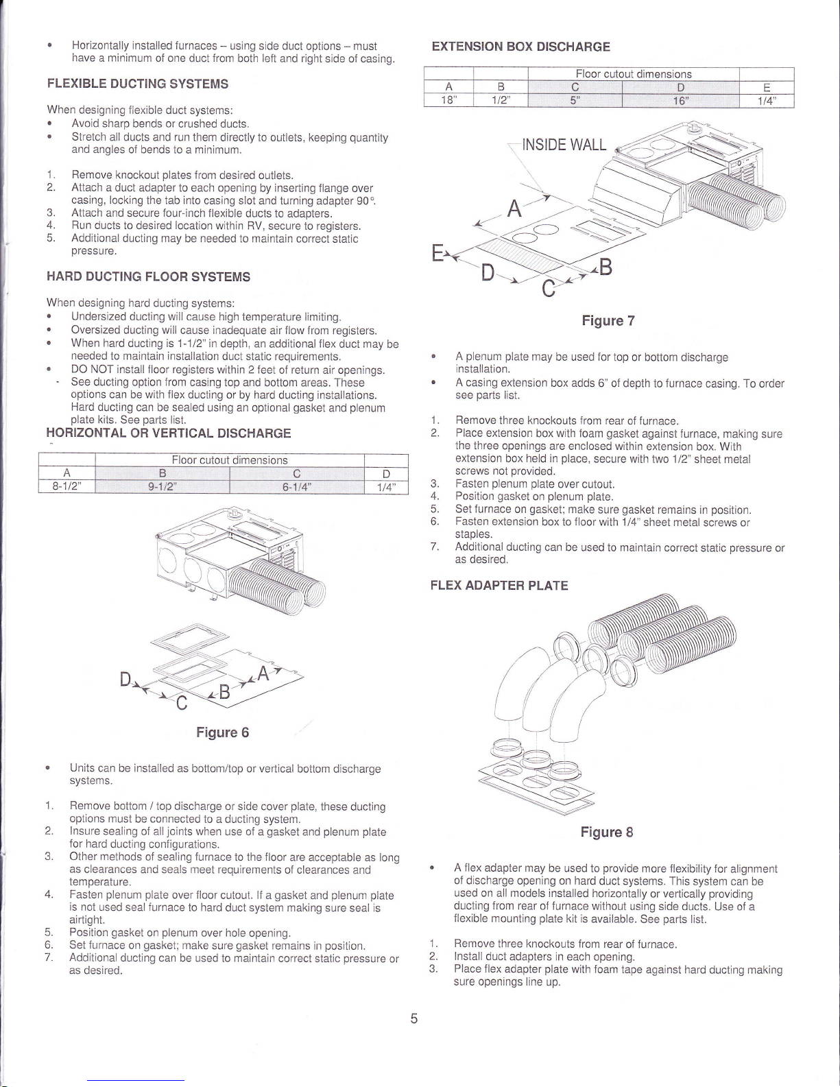
Horizontally
installed furnaces
-
using side duct
options - must
have
a minimum of one
duct
from
both lelt
and
right
side of casing
FLEXIBLE
DUCTING
SYSTEMS
When designing
flexible duct
systems:
.
Avoid
sharp bends or
crushed ducts.
.
Stretch
all ducts and run
them directly to outlets, keeping
quantity
and angles
of bends to a minimum.
Remove
knockout
plates
from
desired outlets.
Attach
a duct
adapter to each opening
by
inserting
flange over
casing, locking
the tab into
casing slot and turning
adapter 90"
Attach
and
secure
lour-inch
flexible
ducts to adapters.
Run
ducts to
desired
location
within RV,
secure to registers.
Additional
ducting may
be
needed
to maintain
correct static
pressure.
HARD DUCTING
FLOOR
SYSTEMS
When
designing hard
ducting
systems:
o
Undersized
ducting
will
cause high
temperature limiting.
.
Oversized
ducting
will
cause inadequate
air
flow
from registers.
.
When
hard ducting is 1-112"
in depth, an
additional
flex
duct may
be
needed
to maintain installation
duct
static
requirements.
.
DO NOT
install floor registers
within 2 feet
of
return
air openings.
-
See ducting
option
from
casing
top and bottom areas. These
options
can
be
with flex
ducting
or by
hard
ducting installations.
Hard
ducting can be sealed
using an optional
gasket
and
plenum
plate
kits.
See
parts
list.
HORIZONTAL
OR
VERTICAL
DISCHARGE
Figure
6
Units
can be installed
as bottom/top
or
vertical
bottom
discharge
systems.
Remove
bottom
/ top discharge
or side cover
plate,
these
ducting
options must
be connected
to a ducting system.
lnsure
sealing of
all
joints
when
use of a
gasket
and
plenum plate
for hard
ducting configurations.
Other
methods
of sealing
furnace
to the floor
are acceptable
as
long
as
clearances
and seals meet requirements
of clearances
and
temperature.
Fasten
plenum
plate
over floor
cutout.
lf
a
gasket
and
plenum plate
is not
used
seal
furnace
to hard
duct system making
sure seal
is
airtight.
Position
gasket
on
plenum
over
hole
opening.
Set
furnace
on
gasket;
make
sure
gasket
remains in
position.
Additional
ducting
can be used to maintain
correct static
pressure
or
as desired.
EXTENSION
BOX DISCHARGE
INSIDE
WALL
Figure 7
A
plenum
plate
may
be used for
top or bottom discharge
installation.
A
casing extension
box adds
6" of depth
to
furnace
casing. To order
see
parts
list.
Remove
three knockouts from
rear of furnace.
Place
extension
box with foam
gasket
against furnace,
making sure
the
three openings
are enclosed within
extension
box.
With
extension
box held in
place,
secure with
lwo 112"
sheet metal
screws not
provided.
3.
Fasten
plenum plate
over cutout.
4. Position
gasket
on
plenum plate.
5. Set furnace
on
gasket;
make
sure
gasket
remains in
position.
6. Fasten
extension
box to
floor
with 1i4"
sheet metal
screws or
staples.
7. Additional
ducting
can be used
to
maintain
correct
static
pressure
or
as
desired.
FLEX
ADAPTER
PLATE
Figure
8
A flex
adapter may
be used
to
provide
more flexibility
for alignment
of discharge
opening on hard
duct systems. This
system can be
used on
all
models
installed horizontally
or vertically
providing
ducting from
rear
of
furnace
without
using side
ducts. Use of a
flexible mounting
plate
kit is
available.
See
parts
list.
Remove
three knockouts from
rear
of
furnace.
lnstall
duct adapters in
each opening.
Place
flex
adapter
plate
with foam
tape
against hard ducting making
sure openings line
up.
1.
2.
1.
J.
4.
5.
6.
7.
Floor
cutout dimensions
B
c
D E
18" 1t2"
5"
to
114"
Floor cutout dimensions
A
B
c D
8-1t2 s-'t/2"
6-1t4" 1t4"
4.
(
6.
7.
With
plate
held
in
place,
fasten
plate
to ducting
using
screws
or
staples
as
need to
keeP
it flat.
lnstall three
duct adapters
into
flex adapter
plate.
Attach
flexible ducting
from
furnace to
ilex adapter
plate
and secure
ducting
in
place
on both
ends.
Additional
ducting
can
be used
to
maintain
correct
static
pressure
or
as desired.
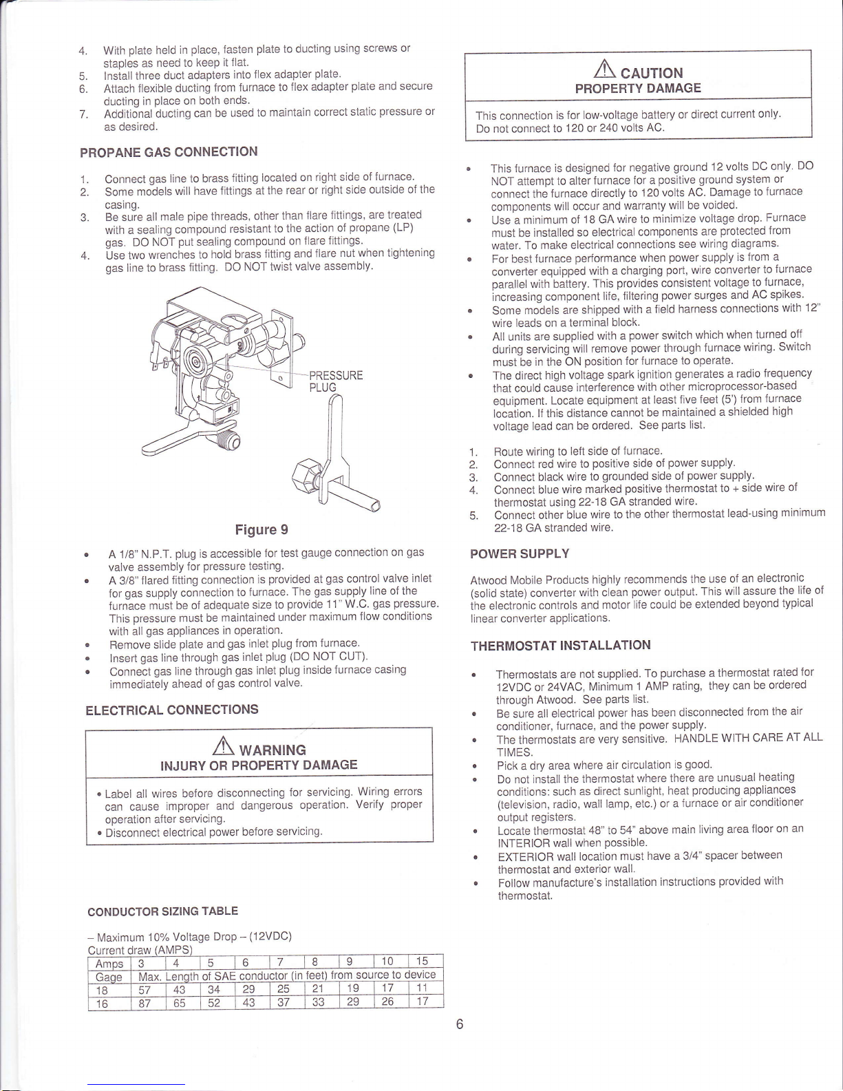
PROPANE
GAS
CONNECTION
1.
Connect
gas
line to brass
fitting
located on
right
side
of Jurnace.
2. Some
models
will have
fittings at
the
rear or
right side
outside of the
casing.
3.
Be suie all
male
pipe
threads,
other
than
llare
fittings, are
treated
with a sealing
compound
resistant
to the
action
of
propane
(LP)
gas.
DO NOT
put
sealing
compound
on
flare
fittings.
4. Use two
wrenches
to
hold brass
fitting
and
flare
nut when tightening
gas
line to brass
fitting.
DO NOT iwist
valve assembly.
Figure 9
.
A 1/B"
N.P.T.
plug
is accessible
for
test
gauge
connection
on
gas
valve assembly
for
pressure
testing.
r
A 3/8"
flared
fitting
connection
is
provided
at
gas
control
valve inlet
for
gas
supply
connection
to
furnace.
The
gas
supply
line of the
furnace
must
be of adequate
size to
provide 1 1" W.C.
gas pressure.
This
pressure must be
mainiained
under
maximum
llow conditions
with
all
gas
appliances
in operation.
.
Remove slide
plate
and
gas
inlet
plug
from
furnace.
.
lnsert
gas
line ihrough
gas
inlet
plug
(DO
NOT CUT).
o
Connect
gas line
through
gas
inlet
plug
inside
furnace
casing
immediately
ahead
of
gas
control
valve.
ELECTRICAL
CONNECTIONS
A
wanNrNrc
INJURY
OR
PROPERTY
DAMAGE
.
Label
all
wires before
disconnecting
for servicing.
Wiring errors
can cause
improper
and
dangerous
operation.
Verify
proper
operation
after servicing.
.
Disconnect
electrical
power
before
servicing.
CONDUCTOR
SIZING
TABLE
-
Maximum
10%
Voltage
Drop
-
(12VDC)
A
"ou,o*
PROPERTY
DAMAGE
This connection
is for
low-voltage
battery
or direct
current
only.
Do
not connect
to
120 or 240
volts
AC.
.
This furnace
is designed
for negative
ground
12
volts
DC only.
DO
NOT attempt
io alter
lurnace
for a
positive
ground
system
or
connect the
f
urnace
directly
to
120 volts
AC.
Damage
to
furnace
components
will occur
and
warranty
will be
voided.
.
Use
a
minimum of
1B GA
wire to
minimize
voltage
drop.
Furnace
must be
installed
so electrical
components
are
protected from
water.
To make
electrical
connections
see
wiring diagrams.
.
For
best
furnace
performance when
power
supply
is from
a
converter
equipped
with a charging
port,
wire converter
to
furnace
parallel
with battery.
This
provides
consistent
voltage to-furnace,
increasing component
life, filtering
power
surges
and
AC spikes'
.
Some
models
are shipped
with a
lield
harness connections
with
12"
wire leads on
a terminal
block.
.
AII units
are supplied
with a
power
switch
which
when turned
off
during servicing
will
remove
power
through
furnace
wiring.
Switch
must be
in
the
ON
position
for furnace
to operate.
.
The direct
high
voltage spark
ignition
generates
a
radio
lrequency
that
could cause
interference
with
other
microprocessor-based
equipment.
Locate equipment
at
least
five
feet
(5')
from
furnace
locaiion.
lf this distance
cannot
be
maintained
a shielded
high
voltage
lead can
be ordered.
See
parts
list.
1.
Route wiring
to
left
side
of
lurnace.
2. Connect
red
wire to
positive
side
of
power
supply.
3. Connect
black
wire to
grounded
side
of
power
supply.
4. Connect
blue
wire marked
positive
thermostat
to + side
wire of
thermostat
using
22-18
GA stranded
wire.
5.
Connect
other
blue
wire to the
other thermostat
lead-using
minimum
22-18 GA
stranded
wire.
POWER SUPPLY
Atwood
Mobile
Products
highly
recommends
the
use of
an
electronic
(solid
state) converter
with clean
power
output.
This will assure
the
li{e of
ihe
electronic
controls
and
motor
life could be
extended
beyond
typical
linear converter
applications.
THERMOSTAT
INSTALLATION
o
Thermostats are
not
supplied.
To
purchase
a thermostat
rated
for
12VDC
or
24VAC,
Minimum
1 AMP
rating, they
can
be ordered
through
Atwood. See
Parts
list.
o
Be
sure
all electrical
power
has been
disconnected
lrom
the
air
conditioner,
furnace, and
the
power
supply.
.
The
thermostats
are
very sensitive.
HANDLE
WITH
CARE
AT ALL
TIMES.
.
Pick a dry area
where air
circulation
is
good.
.
Do not
install the thermostat
where there are
unusual
heating
conditions:
such
as
direct sunlight,
heat
producing
appliances
(television, radio,
wall
lamp, etc.) or a
furnace
or air
conditioner
output
registers.
Locate thermostat
48" to
54" above
main
living area
iloor
on an
INTERIOR
wall
when
possible.
EXTERIOR
wall
location
must
have a 3/4"
spacer
between
thermostat
and exterior
wall.
Follow
manufacture's
installation
instructions
provided with
thermostat.
Current
draw
(AMPS
Amps
4 5
b
7
8 9
10
iE
Gaqe
Max.
Lenqth of SAE
conductor
(ln
feet)
from source
18
F,7
43
34
29
25
21 19
17
'1
1
16
87
65
az
/a
ca
29 26
17
OPERATING INSTRUCTIONS
A
wnnrurruc
FIRE
OR EXPLOSION
Do not
operate furnace while vehicle is in motion or being towed.
.
During
initial firing of this furnace, a burn-off of excess oils
remaining
from manufacturing
process
may cause smoking or
fumes
for 5-10
minutes.
.
NOTE: if furnace
should
lock
out, the
blower will
go
off in 3 minutes
and
remain
off until unit
is
reset by
reactivating
the thermostat.
STOP! Read
Users
lnformation Manualsupplied with
furnace.
'1
. Turn
the
manual valve
(if
so equipped) or the
valve
at the outside
LP
tank to the
"OFF""
position
DO NOT force. NOTE: This furnace
is
equipped with a valve
shut-off switch
with switch in
"OFF"
position.
Gas will
not flow
to burner
nor will
the
furnace
operate.
Turn
switch to
"ON"
position.
2. Set
thermostat above
room
temperature to begin blower operation.
A slight
delay
will occur before
the
blower comes on. Allow blower
to run for 1 minute for
combustion chamber
purge
cycle.
lf blower
does
not
come on
go
to shut down and contact
your
dealer or a
'
Iocal
recreational vehicle
service agency.
3. After 1 minute,
the blower
may not
be
running
at this time,
move
thermostat lever below room temperature. Wait approximately 2
minutes for
blower to
go
otf.
4.
Open manual
shut-off
valve
(if
so equipped) or the
valve
at the
'
outside LP tank. Correct operation characteristics depend on the
valve
being
positioned
fully
open.
Never
attempt to operate
with
a
valve
partially
closed.
Turn
shut-off switch to
"ON"
position.
5. Set thermostat lever to desired
setting.
lf set above room
temperature, blower
will
come on.
6. Allow
30 seconds for main burner to light after blower comes on.
This
furnace is
equipped
with
an
ignition
device
which
automatlcally
lights
the burner.
DO NOT
try to
light
the burner by
hand.
7. lf
burner does not
light,
repeat Steps 1 through 5.
B. lf
after three
(3)
attempts
with no ignition,
go
to shut down and
contact
your
dealer or a
local recreational vehicle
service agency.
Do
not
continue to
cycle furnace
through thermostat
in
an attempt to
get
ignition.
To
Shut Down
1.
Set the thermostat to
lowest
setting,
move
lever to
"OFF"
position.
2. Turn
manual shut off
valve
(if
so equipped) to the
"OFF"
position.
Do not
force.
SYSTEM CHECKS
A
wannrnc
FIRE
OR EXPLOSION
Never
check
for leaks with
an open
flame. Turn
on the
gas
and apply soapy
water
to all
joints
to see
if
bubbles are
formed.
PROPANE
GAS PRESSURE TEST
The furnace
and any individual shut-off
valve
must be disconnected from
gas
supply
piping
system during any
pressure
testing of
system
at test
pressures
of
more
than
1/2" PSl.
Before
furnace is
connected,
piping
systems
must
be tested to be
leak
free. The test must maintain
air
pressure
of a least 6"
of
mercury
or
3"
PSI for
at
least 10 minutes.
The
entire
piping
system must be
maintained
within a range
of
10
to
14"
WC when
all appliances are
in
operation. Test
gas
connections
for
leakage with a leak
test solution.
STATIC
PRESSURE
TEST
.
Special tools required
to take casing static
pressures.
Please refer
to
Engineering
addendum when installing
the {urnace.
This
will
provide you
with
allowable
maximum
case static
pressures
with each
possible
variation
of duct configurations. The
addendum
is
available
from
you
Atwood Field
Service
Representative
or by calling Atwood Service.
Reducing
the
number
of duct turns and stretching
the ducts
will increase
airflow
and reduce
static
pressure.
Adding
ducts or
increasing
the
discharge
(hard
duct) system will also reduce
static
pressure.
You must
follow
the manufacture's recommendations
and specifications
for
optimum
performance
and
proper
operation.
IGNITION
CONTROL DIAGNOSTIC
CODES
The following charts
give
the diagnostic codes
given
by the
ignition
control
when faults
are
present.
.
A
soft
lockout
is
a condition that
is
timed and
will make
additional
attempts to correct the
problem.
A hard lookout requires resetting oJ
the thermostat
or turning the
power
switch oJf, then back on.
STANDARD 3
TRIES FOR IGNITION
CONTROLS
DIAGNOSTIC CHART
FAULT LED INDICATION
LOCKOUT
lnternal Circuit Board
Failure
Steady On,
No
Flashing Hard
Limit Switch/Airflow
Problems
1-Flash
With
3-Second
Pause
Soft
Flame
Sense
Fault
2-Flashes With
3-Second
Pause
Hard
lgnition Lockout Fault
3-Flashes With
3-Second
Pause
Solt
2.STAGE 3
TRIES
FOR IGNITION
CONTROLS
Note:
(on
LD models
control
ts not vtstble
DIAGNOSTIC
CHART
FAULT
LED INDICATION LOCKOUT
Low lnout voltaoe 1-Flash with 3 second oause
Sofl
lonition failure
2-Flash With
3-Second Pause Soit
Open
hiqh limit
3-Flashes
With
3-Second Pause Soit
Stuck Sail Switch 4-Flashes With 3-Second Pause Hard
lonition fault
5-Flashes
with
3-second
pause
Hard
 Loading...