

Page 1
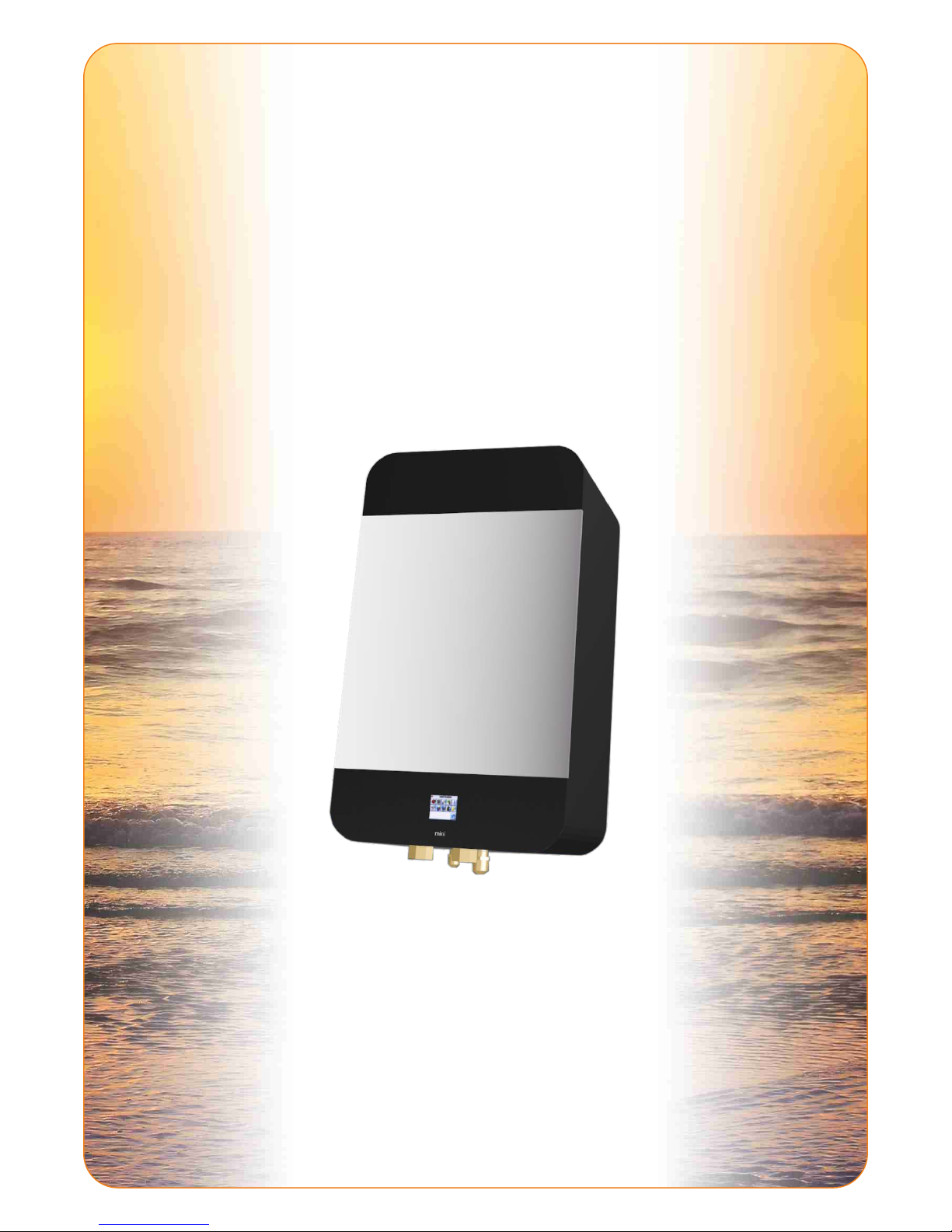
ATW-MINI
AIR-TO-WATER HEAT PUMP
User Guide
Care and Maintenance Manual
Installation Manual
Page 2

CONTENTS
IMPORTANT WARNINGS .................................... 3
1. THE PRODUCT .................................... 3
2. APPLICATION .................................... 3
3. TECHNICAL DESCRIPTION OF THE PRODUCT .................................... 3
4. SAFETY PRECAUTIONS .................................... 4
5. STORAGE AND TRANSPORT .................................... 4
6. SPECIFICATIONS .................................... 5
7. OPERATING PRINCIPLE .................................... 6
8. INSTALLATION AND POSITIONING .................................... 7
9. CONNECTION OF REGFRIGERANT CIRCUIT .................................... 8
All texts or technichal parametres are subject to change
without further notice. Please check with your dealer.
2
10. SETTING AND OPERATION .................................... 8
11. MAINTENANCE .................................. 16
REFRIGERANT CIRCUIT .................................. 17
DIMENSIONS .................................. 18
Page 3
IMPORTANT WARNING
3. TECHNICAL DESCRIPTION OF THE PRODUCT
1. THE PRODUCT
Dear Customer,
thank you for purchasing the ATW-MINI Heat Pump. We believe you will be satisfied with this product
and that this product will bring comfort into your home.
As this product is a complex appliance, pay high attention to this User Guide. This guide will make you
completely familiar with the product application, placing, construction and will provide you with other
necessary information.
Before you connect the heat pump to the network, contact your local distributor for authorization.
Connection, service and inspections of the electrical installation can only be done by an authorized electrical
installation company. The Certificate of Warranty is not valid without confirmation from such a company.
The ATW-MINI Heat Pump is designed for heating of family houses or smaller industrial buildings. The product
is to be connected to low-temperature heating systems. This heating system is best suitable for floor heating,
wall and ceiling heating.
Connection to the classical wall convectors is theoretically possible, but it is limited by the maximum temperature
of the output heating water (50°C, 60°C in High Power systems). At this temperature, the COP (efficiency) is lower.
When connecting to the wall convectors, it is necessary to calculate the power at an input water temperature of
45-50°C and to compare it with the thermal loss of the given room.
The heat pump can be used as a source of cooling water.
2. APPLICATION
The MINI Heat Pump is a split system (divided):
Indoor unit MINI IO-15
Outdoor unit AOY(*)14, 18, 30 36, 45, 54, WOYG112, 140, WOYK112, 140, 160
Outdoor temperature sensor, indoor temperature sensor
User Guide
Certificate of Warranty
Basic construction components:
Outdoor Evaporator
This unit is made from a steel plate with high-quality anti-corrosive treatment by electrostatic pulverized
paint. The core of the unit is a two-step DC inverter compressor, which represents an innovation in the field of
heat pumps and which guarantees reliability and long lifetime. Other parts include an evaporator with anticorrosive treatment and a lifetime of over 30 years, fans with variable rotation speeds, an electronic expansion
valve, controlling and measuring components.
Indoor Unit
The core of the unit is a high-quality refrigerant/water heat exchanger. Other essential part is a high-quality
regulator with sophisticated software which is responsible not only for the operation of the heat pump but
also for the total temperature regulation in the building. The regulator ensures cascade regulation of the heat
pump with backup heater during insufficient power of the heat pump.
It is also possible to connect the appliance to PC through internet interface for comfortable and effective
control of the heat pump.
3
Page 4
4. SAFETY PRECAUTIONS
The Heat Pump is an electrical appliance operating under 230V voltage! The product can only be installed and
serviced by an authorized electrician. In case of fire, do not use water or foam extinguishers. Use only the
dry-powder or carbon dioxide extinguishers!
In case of refrigerant leakage, switch off the outdoor unit breaker and contact the servicing organization
mentioned on the label on the indoor unit. The R410A refrigerant is non-flammable, inexplosive and non-toxic.
Under no circumstances should you try to stop the refrigerant leakage by yourselves. The refrigerant is
generating very low temperatures (as low as -50°C). In case of indoor leakages, ventilate the room properly. In
case of inhalation of refrigerant and fire exhausts, bring the exposed person into a ventilated room and call your
local medical emergency number. If hit by the liquid refrigerant, dry the affected place immediately and warm it
(e.g. by a blanket). If eyes are affected by the liquid refrigerant, wash them out with water and call your local
medical emergency number.
In case of fire emergency, disconnect the appliance from the electrical network and extinguish the fire with
dry-powder or carbon dioxide extinguishers.
In case of heating water leakage, switch off all the indoor unit breakers and contact the service organization
mentioned on the label on the indoor unit.
During manipulation with the refrigerant piping (cleaning, maintenance), use protective working aids (such as
gloves or glasses).
Do not insert fingers into an operating fan of the outdoor unit, serious injury might occur!
Exposing yourself to a direct airflow for extended period of time may lead to serious hyperthermia.
Local laws and standards must be observed.
5. STORAGE AND TRANSPORT
Outdoor unit AOY(*) 18, 30, 30, 36, 45, 54:
Dust/free, non-agressive environment
Temperature -10°C to +45°C
Maximum humidity 90%
The outdoor unit must be stored and transported in vertical position and in the original box. If necessary, protect
the fragile parts (e.g. exchanger).
ATW-MINI indoor unit:
Dust/free, non-agressive environment
Temperature +5°C to +45°C
Maximum humidity 70%
4
Page 5
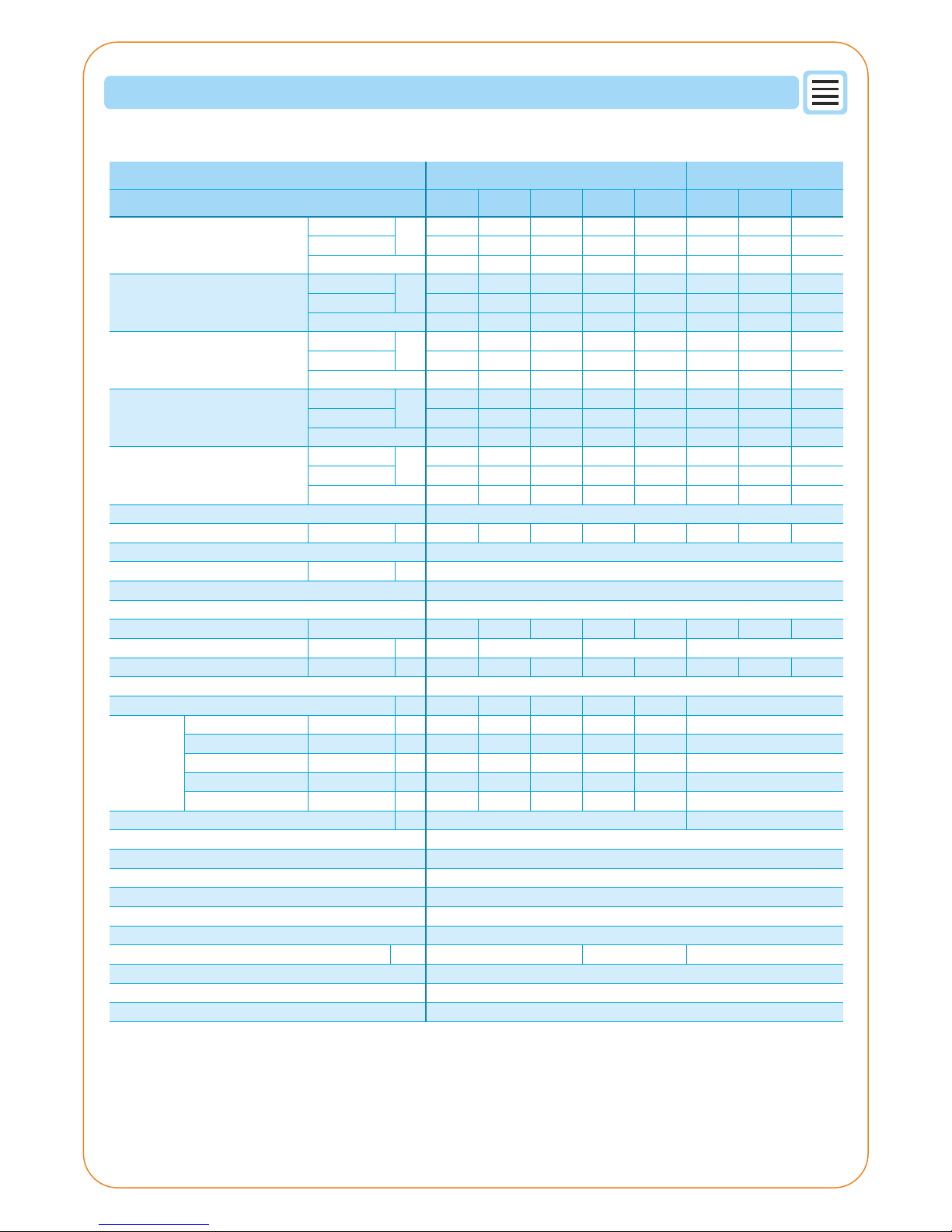
6. SPECIFICATIONS
Series
Comfort High Power
Type
Mini 5 Mini 8 Mini 11Mini
14
Mini
16
Mini
11 HP
Mini
14 HP
Mini
16 HP
5 8 11,1 14 16 11,2 14 16
1,22 1,9 2,67 3,5 4,05 2,55 3,22 3,72
4,1 4,2 4,15 4 3,95 4,4 4,35 4,3
4,06 8 10 13 14 11,2 14 15,1
1,23 2,5 3,13 3,94 4,38 3,45 4,4 4,87
3,3 3,2 3,2 3,3 3,2 3,25 3,18 3,1
3,46 7,9 8,63 11 11,5 11,2 14 15
1,31 3,12 3,6 4,4 4,79 3,92 5,15 5,56
2,65 2,53 2,4 2,5 2,4 2,86 2,72 2,7
5,67 8 9,5 13,2 14,4 10,5 13,1 15,1
1,7 2,47 2,97 4,13 4,57 2,9 3,7 4,42
3,33 3,24 3,2 3,2 3,15 3,62 3,54 3,42
3,15 7 7,4 9,5 10 10,5 13,1 14,5
1,56 3,41 3,61 4,5 4,85 4,16 5,39 6,39
2,02 2,05 2,05 2,11 2,06 2,52 2,43 2,27
kW
kW
kW
kW
kW
1ø 230V, 50Hz 3ø 400V, 50Hz
A
42 dB/1m
cm 65,5 × 40,5 × 28,6
plate stainless soldered
DC-variable speeds
12,5 17,5 18,5 20 25,9 8,5 9,5 10,5
Max.
H×W×D
58×79×30
83×90×33 129×90×33 129×90×33
39,0 39,0 40,0 41,0 41,0 41,0 41,0 41,0
dB(A)
cm
(netto) kg
H×W×D
44 62 62 98 105 109 109 109
R410A
kg 1,35 1,7 1,7 3,35 3,35 2,5
DC-inverter (variable-speed)
electronic expansion valve
105 hPa
18 m
0,18 MPa / 0,55 MPa
Al-Cu vertical
hot gas through reverse valve
G1"
15-95%
600 - 2 500 1 000 - 5 500 1 000 - 7 500
Max. m 15 15 20 20 20 15
Max. m 15 15 20 20 20 15
°C -15 ~ 24 -20 ~ 35
Liquid mm ø 6,35 ø 9,52 ø 9,52 ø 9,52 ø 9,52 ø 9,52
Gas mm ø 12,70 ø 15,88 ø 15,88 ø 15,88 ø 15,88 ø 15,88
Min. / Max. m 5/15 5/20 5/20 5/20 5/20 5/20
3
m /h
+7°C / +35°C floor heating
Heating capacity
Input power
COP
+2°C / +35°C floor heating
-7°C / +35°C floor heating
+7°C / +45°C radiators
-7°C / +45°C radiators
Power source
Current
Noise level (indoor unit)
Dimensions (indoor unit)
Heat exchanger
Fan motor
Noise level (Sound pressure)
Dimensions (outdoor unit)
Weight (outdoor unit)
Refrigerant
Refrigerant amount
Connection
pipes
Diameter
Length
Length (chargeless)
Height difference
Diameter
Operation range
Compressor
Regulation of refrigerant circuit
Pressure loss of hot water (indoor unit)
Max. height of water column
Max. operation overpressure / HDW
Evaporator
Air flow
Defrosting
Heating circuit connection
Relative humidity limits
Heating capacity
Input power
COP
Heating capacity
Input power
COP
Heating capacity
Input power
COP
Heating capacity
Input power
COP
Notes:
The values of heating capacity/power input/COP are based on measurement of EN14511 standard.
Sound pressure level measured at distance of 5m from the device, 1.5m from the ground.
5
Page 6
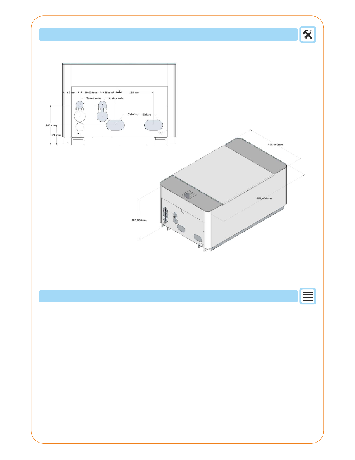
DIMENSIONS
7. OPERATING PRINCIPLE
The heat pump appliance is used to acquire low-temperature energy from the selected source and its transfer to
higher temperature level. The air to water heat pump extracts heat from the ambient air.
The core of the heat pump serves as an efficient compressor through which the refrigerant is compressed and
then expanded in a hermetically closed circuit. This process makes the best of the refrigerant qualities in this
case, the ecological refrigerant R410 is used.
On the entry side (outdoor unit and its evaporator), the outdoor air is run by the fan through the heat transfer
surface of the evaporator. The refrigerant, which passed through the expansion valve and is quenched to
temperature lower than the temperature of the ambient air, circulates inside the evaporator.
Refrigerant is warmed on the evaporator (for example from -17°C to -10°C) and the acquired heat is stored in
the refrigerant and is further pressed by the compressor and distributed into the condenser (indoor unit).
The refrigerant then condenses on the indoor unit plate exchanger and thus the heat is transferred to the
heating medium (heating water).
The condensed refrigerant then heads back into the expansion valve and the whole cycle repeats itself over and
over again.
6
Page 7
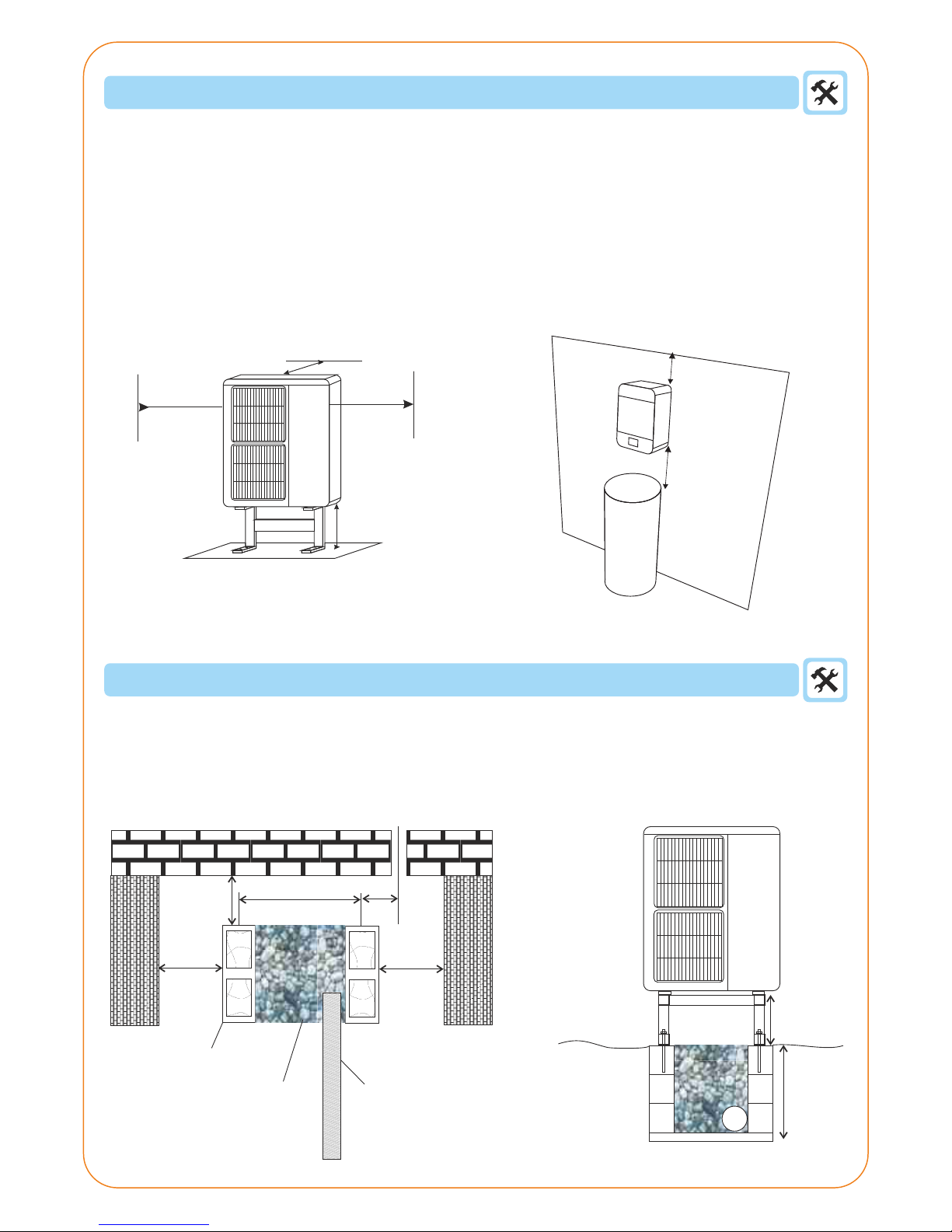
65 cm
50 cm
65 cm
min. 30 cm
8. INSTALLATION AND POSITIONING
The installation must be performed by a professional company authorized by the manufacturer. Do not install
the appliance by yourself. The appliance might get damaged and people injured.
It is possible to suspend the indoor unit on the wall. It has to be placed in the room in a way that enables the
access for service and maintenance (see the illustration under).
The outdoor unit is to be attached to a stand supplied by the manufacturer as an accessory. The stand is
necessary for an appropriate evaporator defrosting. This stand must be firmly fastened to a concrete base large
enough to prevent the unit from toppling over in windy weather. Its position must be chosen with sufficient
space for free airflow to the evaporator and for easy service access (see the illustration below and refer to
service and installation manual for further information).
When installing the outdoor unit in a dense urban area, make sure to observe the noise regulation standards. In
some cases, a noise test might be necessary.
Base of the outdoor unit
It is recommended to place the outdoor unit on a concrete base. Fill the space between the planking blocks with
pebbles. In winter, the condensate will drain to non-freezing depth and wont create ice coating. In case of
impermeable earth, the situation can be improved by installing a drainage hose and by conducting the
condensate away from the area.
min 300 mm
min 300 mm
min 600 mm
min 450 mm
min 450 mm
650 mmAOY36/45/54
540 mmAOY4/18/24
180 mm
Terrain
Base, concrete
planking blocks
Drainage Hose
Gravelous sand,
pebbles
200 mm
100 mm
7
Page 8
8
9. CONNECTION OF THE REFRIGERANT CIRCUIT
The heat pump refrigerant circuit connection must be performed by an authorized installation company or
a company certified or trained in air-conditioning and refrigeration services.
Do not connect the refrigerant circuit by yourself. There is a serious danger of injury from
refrigerant. The refrigerant pressure is up to 4,5Mpa and its temperature is as low as -50°C!
10. SETTING AND OPERATION
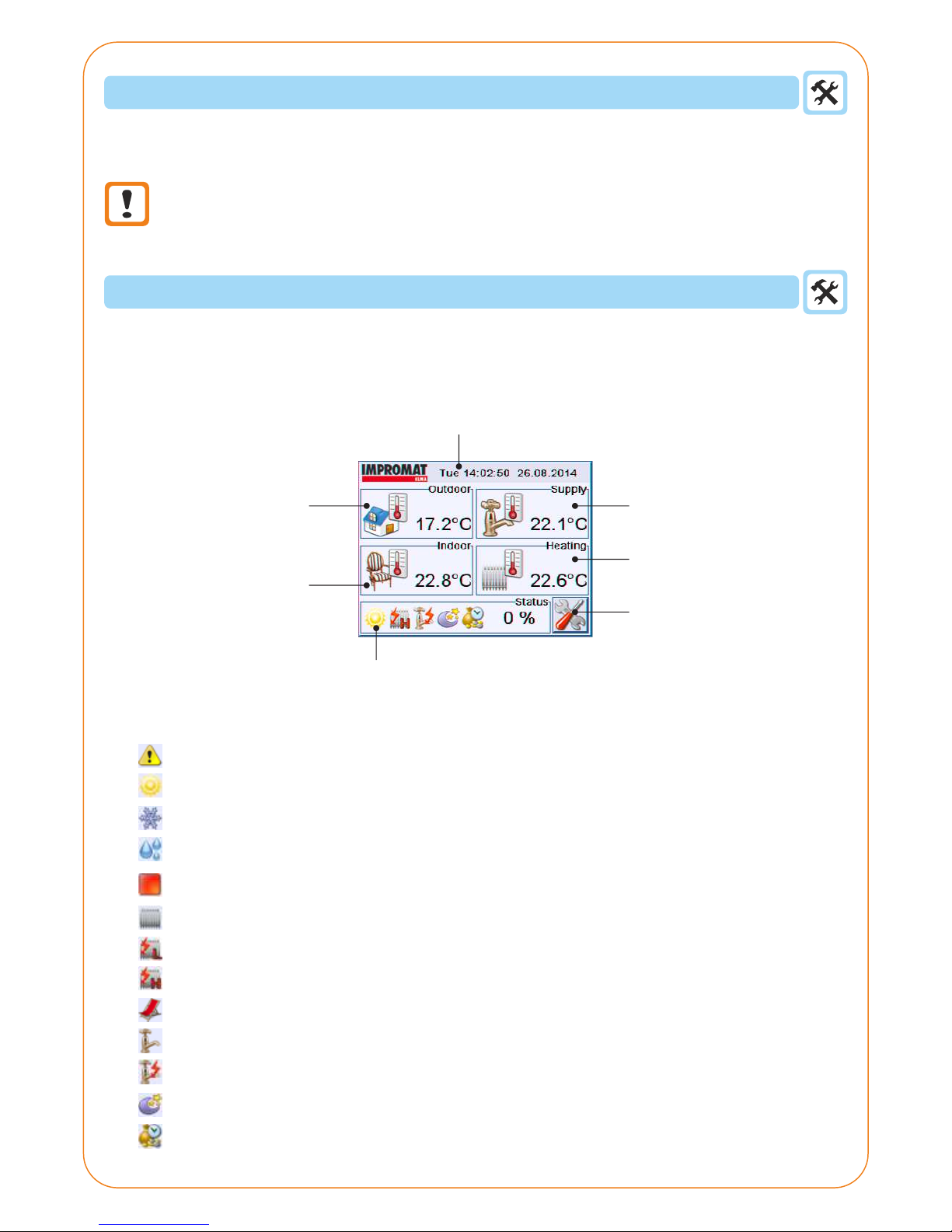
10.1. MAIN DISPLAY SCREEN
Status of the device:
Error - call the service!
The device operates in heating mode
The device operates in cooling mode
Defrosting of outdoor unit in progress
The device is switched off
Water heating in progress
Water heating with first stage of bivalent activated
Water heating with first and second stage of bivalent activated
Summer mode is activated (only HDW heating)
HDW heating in progress
HDW heating using electric heating in progress
The device is in reduced mode
The device is in high tariff operation (rate)
Current time and date
HDW tank
temperature
Settings
Outdoor temperature
Indoor temperature
Current status of the device
Output water
temperature
The main display screen is divided into five basic monitoring windows and buttons serving to enter the devices
setting menu.
Page 9
9
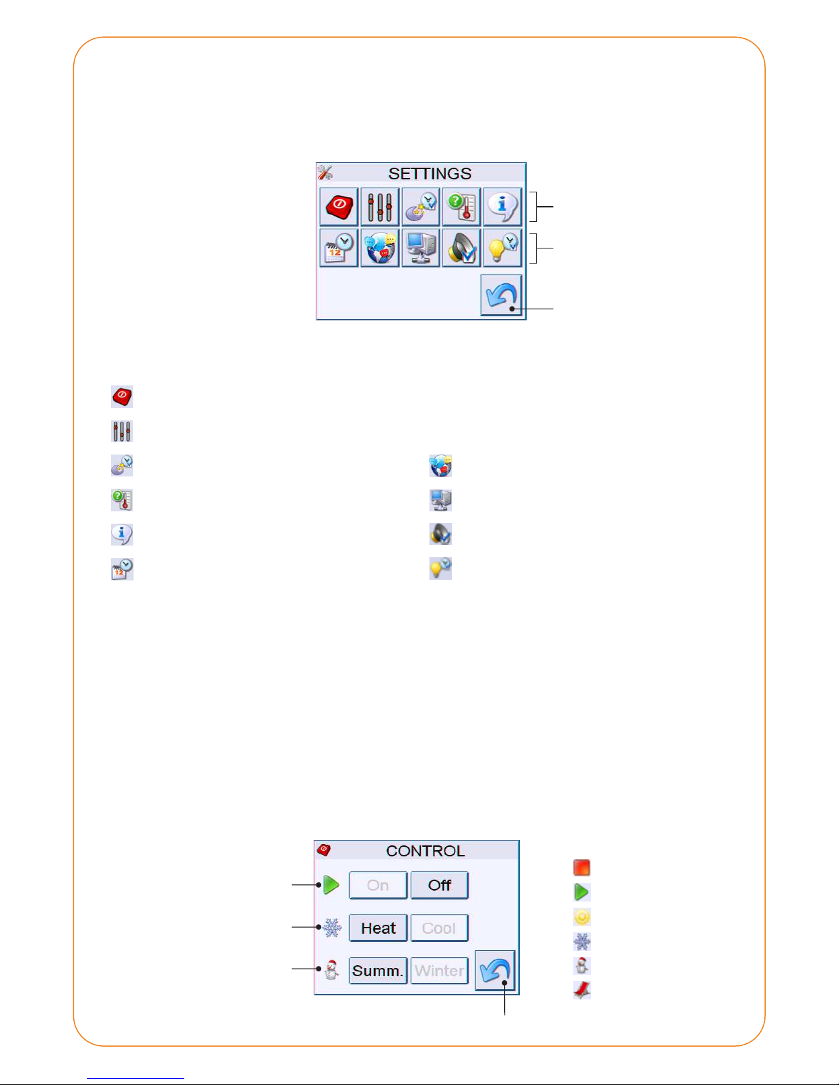
Setting options:
Control (ON/OFF, Cooling/Heating, Summer/Winter)
Parameters setting (temperature sensors, operation limits, equitherm regulation etc.)
Reduction timer
Temperature sensors
Device information
Current time and date
Language
Network setting
Sound setting
Backlight
UTI-INV module
settings
Back to the main screen
UTI-IQCP control panel
settings
10.2. SETTINGS
The Settings menu is divided into two rows of icons. The top row icons are used for the control of the UTI-INV
module (mode, equitherm regulation, HDW etc.), the bottom row icons are used to set the UTI-IQCP control panel
(language, time, network connection etc.).
Status icons:
The device is OFF
The device is ON
The device is Cooling mode
The device is Heating mode
The device is Winter mode
The device is Summer mode
Back
ON/OFF
Mode setting
Season setting
10.2.1 Basic control
The control screen allows the setting of the devices main modes. The icons on the left show the current status.
There are three basic parameters:
On / Off - Turns the device on or off. In the ON state, all set programmes are running. In the OFF state, the divice does not
perform any action. It is possible that after swiching the device off, the circulation pump might still be running for a
while.
Heating / Cooling - In the heating mode, the device heats according to the heating curve, and heats the domestic hot
water. In the cooling mode, the device cools the water at a preset temperature, the HDW heating is not activated.
Summer / Winter - Choosing the season. In summer mode, the device only heats the HDW tank. In winter mode, all
heating operations are performed.
Page 10
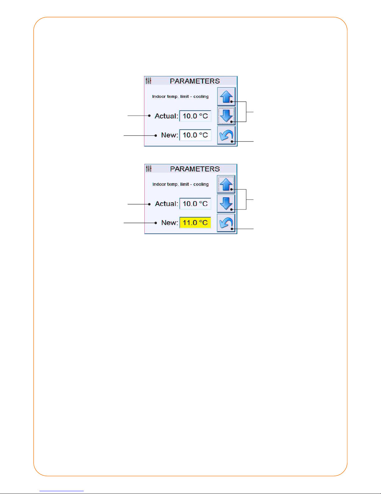
10
Parameters in view mode:
Parameters in edit mode:
Moving up and down
between parameters
Current value
Edited value
Back to the Settings
Current value
New value
(select to edit)
10.2.2 Parameters settings
The menu with a number of parameters that can be viewed, and modified, if necessary. The current value of the
parameter is displayed. If the parameter is user-editable, a box labelled New is displayed.
Parameters that cannot be edited:
- Mode V2
- Maximum temperature of the refrigerant in the heating mode
- Minimum temperature of the refrigerant in the cooling mode
- Mode V1
Changing the value
up and down
Save and return to
the Settings menu
Editable parameters:
- Time limit - supply water - time during which the HDW tank will be heated.
- Temperature reduction - cooling - how many degrees will the temperature increase during cooling.
- Temperature reduction - heating - how many degrees will the temperature decrease during heating.
- Bivalent temperature - outdoor temperature that causes the outdoor unit shutdown.
- Cooling water temperature - requied water temperature in the cooling mode.
- Power limit - cooling - maximum capacity of the outdoor unit during cooling mode.
- Power limit - heating - maximum capacity of the outdoor unit during heating mode.
- Max. temperature - supply water - maximum temperature in the HDW tank.
- Min. temperature - supply water - minimum temperature in the HDW tank.
- Power limit - supply water - maximum capacity of the outdoor unit during HDW heating.
- Heating water (outdoor +20°) - required heating water temperature at +20°C outdoor temp.
- Heating water (outdoor +12°) - required heating water temperature at +12°C outdoor temp.
- Heating water (outdoor +4°) - required heating water temperature at +4°C outdoor temp.
- Heating water (outdoor -4°) - required heating water temperature at -4°C outdoor temp.
- Heating water (outdoor -12°) - required heating water temperature at -12°C outdoor temp.
- Heating water (outdoor -20°) - required heating water temperature at -20°C outdoor temp.
- Regulation constant - value affecting the communication speed with the outdoor unit.
- Indoor temperature limit - heating - maximum indoor temperature in the heating mode.
- Indoor temperature limit - cooling - minimální indoor temperature in the cooling mode.
Page 11
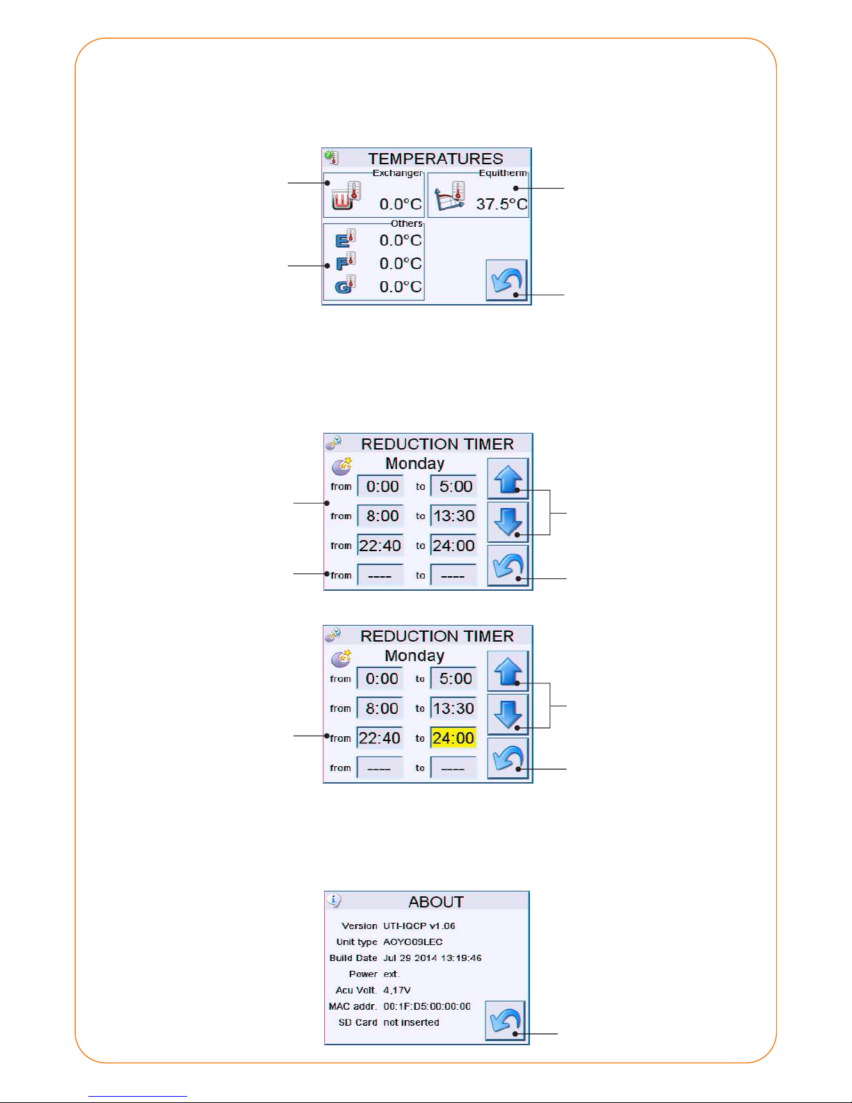
11
Required water
temperature according
to the equitherm curve
Back to Settings
Exchanger temperature
Other sensors
10.2.3 Temperature
List of other temperature sensors that are not shown on the main screen. The exchanger temperature and the
required temperature are displayed. The E, F and G sensors are displyed - these values are only informative and do
not affect the regulation.
For each day of the week, you can select up to four time intervals during which the reductution timer is active.
Move between the days of the week using the arrow buttons. To set the time, click on the corresponding box and
insert the value using the arrow buttons.
Set time intervals
Time interval is not set
Edited value
10.2.4 Reduction timer
Moving between days of the week:
Setting the time intervals:
Changing the time
10 minutes up/down
Moving up and down
between days
Back to the Settings
Save and return to
the Settings menu
Information sheet showing the current version of the control panel, type of the outdoor unit and other
information, including the MAC address of the device (if you are incorporating the panel to the network). The last
line shows if the SD card is inserted.
10.2.5 Device information
Back to the Settings
Page 12
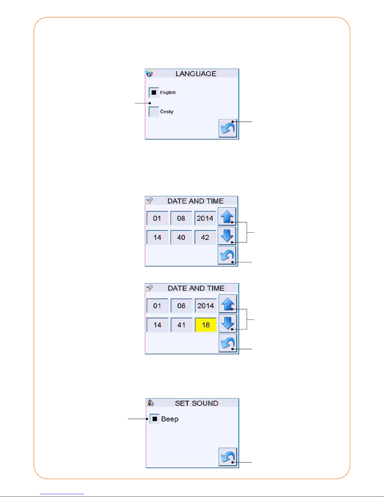
12
Language options
The UTI-IQCP control panel offers three language versions. When you select the language, the user interface will
switch to that language. By pressing the Back button, the setting will be saved and the screen will return to the
Settings menu.
10.2.6 Language setting
Save and return to
the Settings menu
No function assigned
Back
To set the current date or time, highlight the item you want to edit. The value can then be changed using the up
and down arrows. By pressing the Back button, the setting will be saved and the screen will return to the Settings
menu.
10.2.7 Current date and time
Changing the value
up and down
Date and time in view mode:
Date and time in edit mode:
Save and return to
the Settings menu
Sound ON/OFF
It is possible to swich the sound on or off. If the sound is on, the panel will emit beep sounds when making
settings.
10.2.8 Sound setting
Save and return to
the Settings menu
Page 13
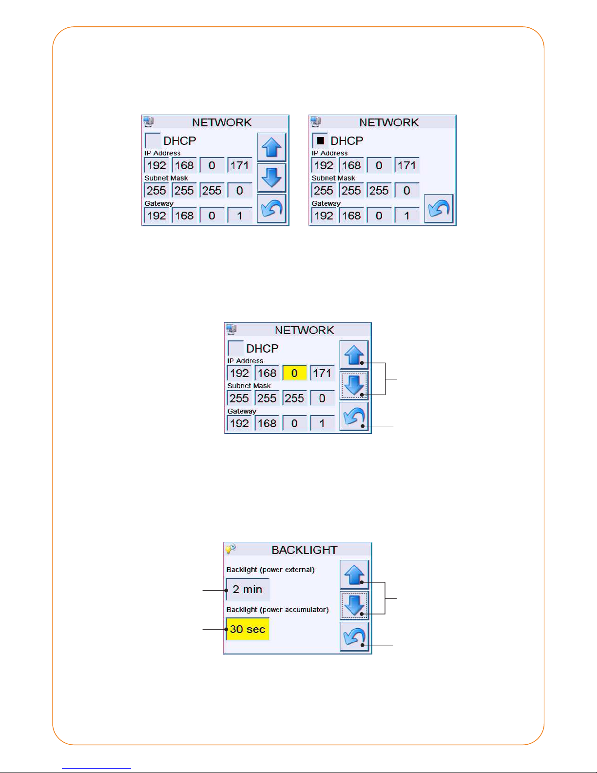
13
DHCP deactivated:
It is possible to set the IP address, subnet mask and gateway of the network so that the devices can be connected to
the network. If the installation permits, it is possible to activate the DHCP server.
10.2.9 Network setting
Note: If you dont know what value to set, do not make any changes, or connect the panel to the network. Please
consult your network administrator.
To set the desired value, click on the item you want to edit. The value can be changed using the up and down
arrows. By pressing the Back button, the setting will be saved and the screen will return to the Settings menu.
Changing the value
up and down
DHCP activated:
Save and return to
the Settings menu
To adjust the backlight of the display, highlight the item you want to edit. The value can be changed using the up
and down arrows. By pressing the Back button, the setting will be saved and the screen will return to the Settings
menu.
10.2.10 Backlight setting
Available backlight time lengths:
- on (----), 10 seconds, 30 seconds,1 minute, 2 minutes.
Changing the value
up and down
Backlight
(external power)
Backlight
(battery supplied)
Save and return to
the Settings menu
Page 14
14
10.2.11 Factory settings
If the panel is not responding, or you have made a setting that led to a non-standard function, it is possible revert
the panel to its factory settings:
1. Press the button on the panel for more than 10 seconds. (Note: the button may not be accessible when the
panel is installed in a unit.)
2. Perform the calibration 3x upper left corner, 3x lower left corner, 3x right center.
Factory settings:
- Sound: on
- : onBacklight (external power)
- : 30 secondsBacklight (battery)
- Language: English
- Network settings: IP:192.168.0.100
MASK:255.255.255.0
GW:192.168.0.1
- Password: 1937 (user is always admin)
- Other settings: remain in original state (timer)
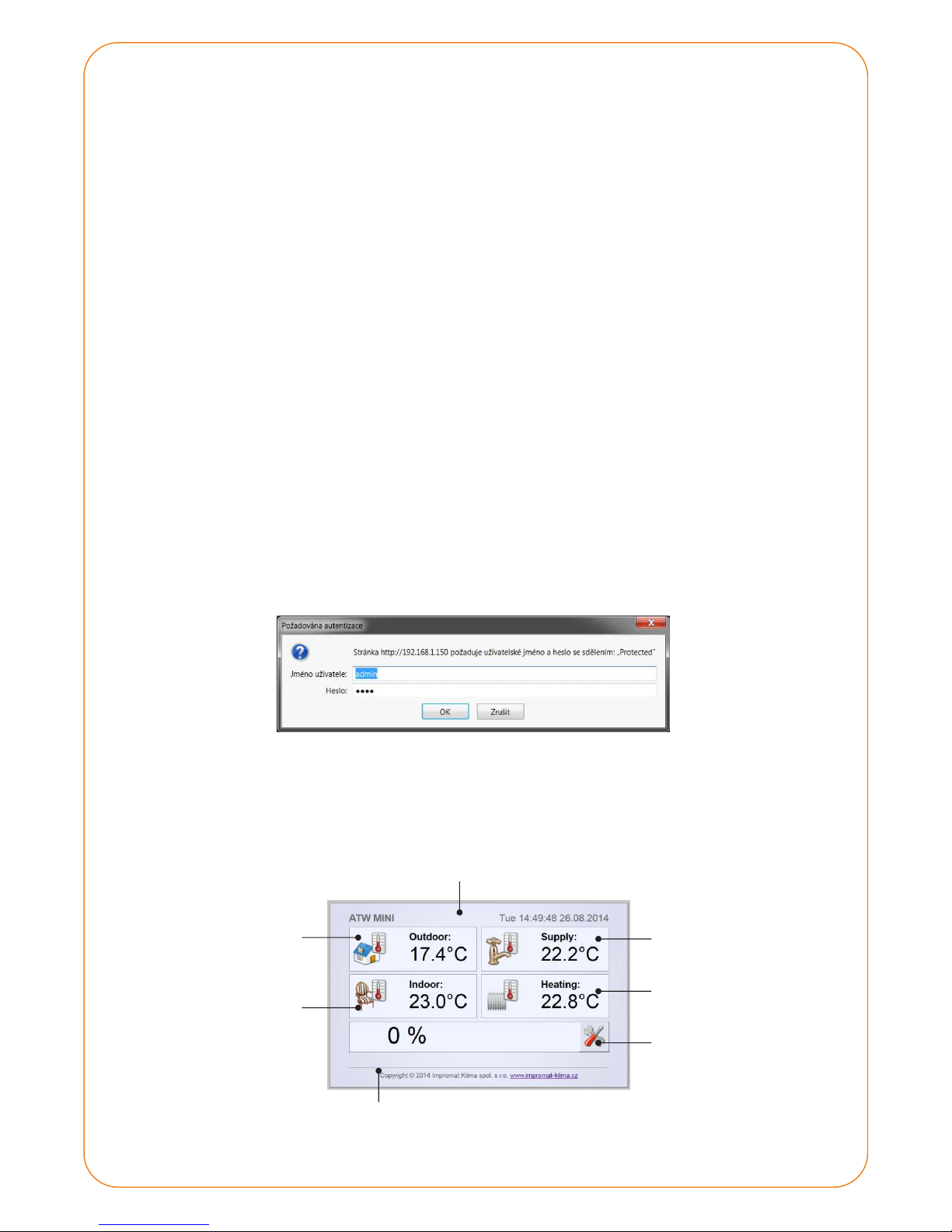
10.3. WEB INTERFACE OF THE PANEL
If the panel network interface is set correctly, it is possible to monitor and control the device from any web
browser by entering the relevant IP address.
Default login:
User: admin
Password: 1937
After login, the main screen is displayed. It is divided into five basic monitoring windows and buttons serving to
enter the device settings.
Current time and date
HDW tank
temperature
Settings
Outdoor
temperature
Indoor
temperature
Current status of the device
Output water
temperature
Status of the device: The status icons are the same as on the touch panel (see Chapter 1).
Page 15
15
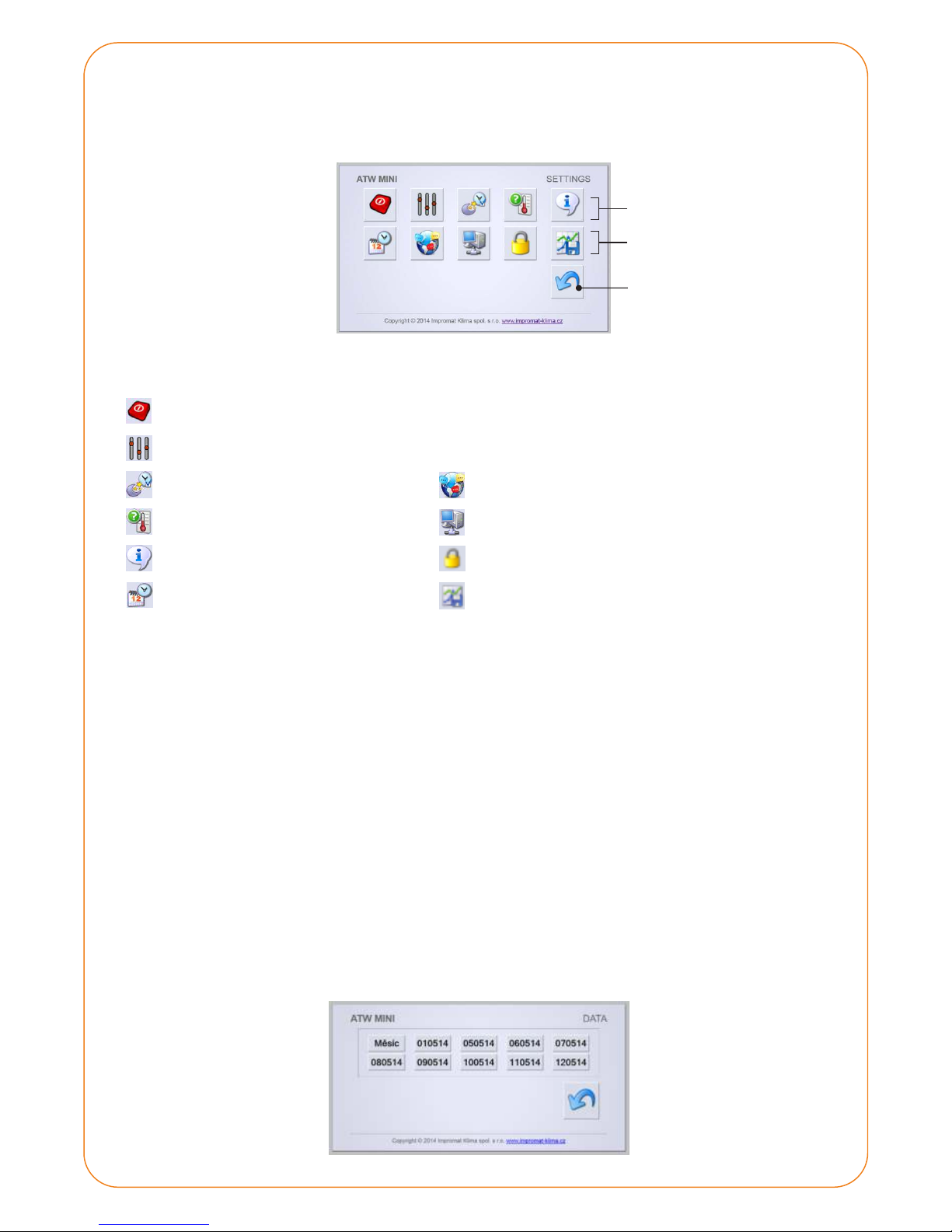
Setting options:
Control (ON/OFF, Cooling/Heating, Summer/Winter)
Parameters setting (temperature sensors, operation limits, equitherm regulation etc.)
Reduction timer
Temperature sensors
Device information
Current time and date
Language
Network setting
Password settign
Data
The settings menu is divided into two rows of icons. The top row icons are used for the control of the UTI-INV
module (mode, equitherm regulation, HDW etc.), the bottom row icons are used to set the UTI-IQCP control panel
(language, time, network connection etc.).
UTI-INV module
settings
Back to the main screen
UTI-IQCP control panel
settings
You can change your password through the web interface. If you forget your password, it is possible to revert the
panel to the factory settings, which will also reset your password. Username cannot be changed.
Password setting
If you for some reason need to create a screenshot of the touch panel (to send to your service organization, for
example), you can access it from: http:// your IP address /screen.bmp
Printscreen
The data from the SD card can be saved to your computer - you can analyze them or send to your service
organization.
By clicking on a specific day, you can open or save the particular record. To open the *.ICH file, it is necessary to
have the IMPROMAT service kit installed.
Data
Page 16
11. MAINTENANCE
Due to its design the heat pump is very easy to maintain. Basic maintenance is performed by the servicing
organization once a year. During this regular maintenance, all important elements of the heat pump are
checked. Special attention is paid to the correct volume of refrigerant in the circuit and a proper operation of
the refrigerant circuit.
It is important to observe the outdoor unit evaporator status. The best way to clean the outdoor unit is by using
the garden washer with hot water. This way, dirt and eventual frost is cleaned from the evaporator.
Do not use high pressure cleaners and any other mechanical tools (brush etc.). The evaporator
is very fine and could easily be damaged. Prior to the outdoor unit evaporator cleaning,
switch off the main breaker of the indoor unit!
Prior to removing the heat pump cover, disconnect the heat pump from the network.
There is a great risk of injury by electric current.
The indoor unit requires minimal maintenance. Use a wet cloth to clean the dust from the upper casing. Be extra
careful when cleaning the heat pump during its operation. It is recommended to cleaning the indoor unit after
the heating season and when it is disconnected.
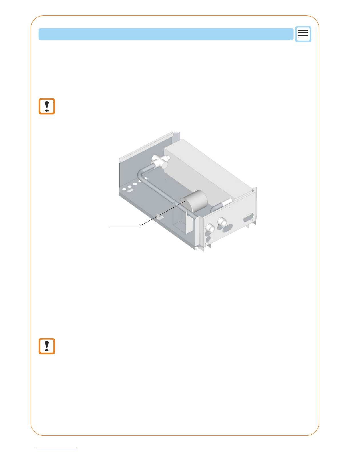
Before the heating season, check the circulation pump operation for possible jamming. This is indicated by
a circulating pump lamp. The pump has a automated program which is trying for some time to release the
blocked shaft. Once a year, have the functionality of the expansion tank checked. Also check the heating water
filter.
All this maintenance should better be performed by an authorized organization during regular servicing.
Circulation pump
16
Page 17
Outdoor unit
Indoor unit
17
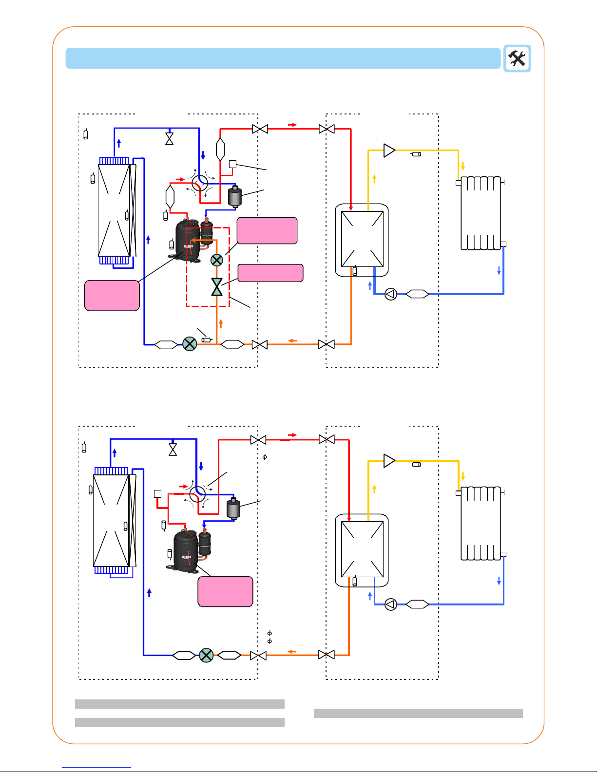
REFRIGERANT CIRCUIT
Models: High Power
Models: Comfort
Filter
TH
HO
TH
O
TH
D
TH
C
TH
PI
TH
HM
15.88mm(5/8")
Piping
9.52mm(3/8")
6,35mm(1/4")
TH
C
TH
D
TH
HM
TH
HO
TH
O
TH
PI
TH
HO
TH
O
TH
D
TH
C
TH
PI
TH
HM
Outdoor unit
Indoor unit
Filter
Expansion valve
Control valve
Filter
Filter
Expansion valve
inlet sensor
Filter Filter
Expansion
valve
Filter
Circulation
pump
Circulation
pump
Exchanger
Exchanger
Piping
Control valve
4-way
valve
Pressure sensor
Accumulator
4-way
valve
Solenoid valve
Injection
expansion valve
Heating
water
sensor
Plate heat
exchanger
Plate heat
exchanger
DC or Scroll
compressor
Compressor
with injection
port
Injection
circuit
High
pressure
switch
Heating
water
sensor
Flow sensor
Flow sensor
Heating
emitter
Heating
emitter
Accumulator
Compressor temperature sensor
Compressor discharge sensor
Exchanger sensor - centre
Exchanger sensor - output
Outdoor temperature sensor
Inner exchanger sensor
Page 18
18
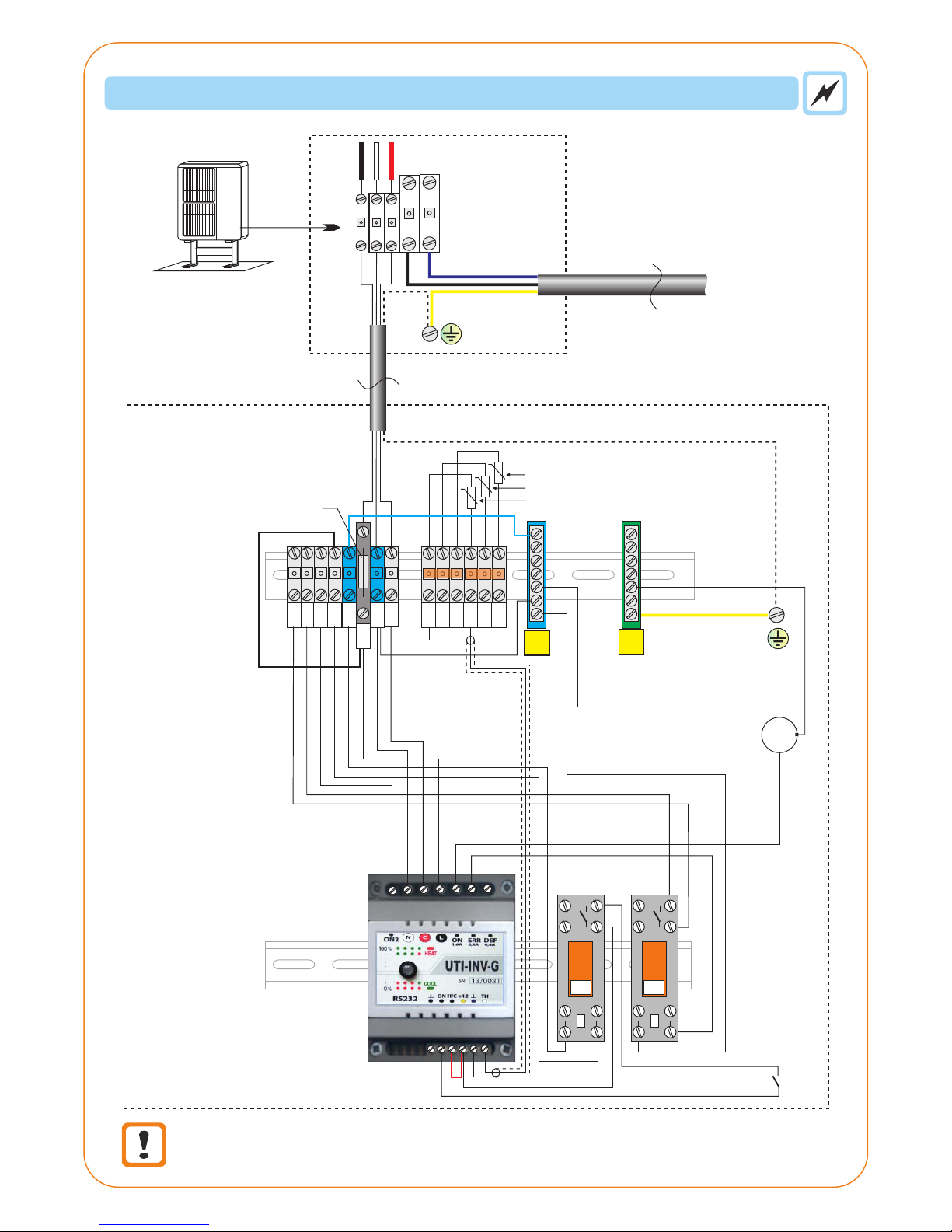
WIRING
Outdoor unit conductor colours must conform with indoor unit terminal descriptions.
Incorrect connection could damage the communication module!
1
2
3
L
N
2
4x 1,5 Cu mm
XL XN XC
XNS
XL
XL-S
XN-S
Po
4A
ETS sensors:
A - exchanger
C - heating water
H - outdoor (or B indoor) air
XETSG
XETS+
XNS
XNS
ON2
ON
1,6A
ERR
0,4A
DEF
0,4A
N
C
L
XNS
X1-C
X1-N
X1-L
XUtlum
X-Biv
XBcom
N
PE
blue
FS
K1 K2
M
J1
J2
J3
Outdoor unit
Terminal
Outdoor unit
terminal
Connecting cable
Power supply
blue
blue
light blue
brown
brown
light blue
brown
light blue
brown
brown
brown
brown
black
white
red
Circulation
pump
Flow
switch
 Loading...