

Page 1
VLVDIR
Vandal-Proof
Dome Camera
Instruction Manual
VER.:2.0, NO.: R040152A/3
Page 2
V
V
Thank you very much for purchasing our product. Before operating this
product, please read this instruction manual carefully to ensure proper use.
1. Safety Precautious
CAUTION
RISK OFELECTR I C
SHOCK.D ONO TOPEN!
CAUTION : TO REDUCE THE RISK OF ELECTRICAL SHOCK, DO NOT OPEN COVERS.
NO USER SER
SER
Please be extra careful not to shake the camera.
Please avoid places where there is direct sunlight.
When using this camera in places where the lighting differs greatly,
Please avoid places where temperatures exceed 50
During the night, if a minimum brightness of 0.1 Lux can not be
Disposal of Old Electrical & Electronic Equipment (Applicable in
the European Union and other European countries with separate
collection systems).
Please do not directly touch the sensor element. If necessary, use
a soft cloth moistened with alcohol to wipe off any dust.
please use the auto iris lens with ND filter.
high humidity or where direct rain drops hit, frequent vibrations, or
shocks occur.
achieved, install appropriate light fixtures.
ICEABLE PARTS INSIDE. REFER SERVICINGTO QUALIFIED
ICE PERSONNEL.
℃ or more,
2. Description
The camera uses Sony high sensitive super HAD interline transfer
image sensor, and employs digital signal processor (DSP) chip-set for
image control, and all integrated state circuitry which provide
extremely long life and high reliability. This camera offers excellent
image quality with low lag and high burn resistance, and is not subject
to distortions from magnetic fields.
Highly resistance to shock and vibration, easy to install, this
camera is a very good choice for your color CCTV system.
1
Page 3
3. Feature
Rugged and vandal-Proof.
Employ s Digit al Signal Pro cessor (D SP) chip-set f or image contr o
Pixel number: NTSC=380K/ PAL=440K (EIA=440K/ CCIR=380K)
high resolution models, and NTSC=250K/ PAL=290K (EIA=290K/
CCIR=250K) for normal resolution models.
High sensitivity,
Powerful functions: Auto Electronic Shutter (AES ), Auto Iris (AI),
Auto Gain Control (AGC), Auto White Balance (AWB), and Back
Light Compensation (BLC).
ICR: IR cut filter removable (optional).
Built-in IR LED, effective range up to 20M (optional).
Weatherproofing
low smear, high anti-blooming and high S/N ratio.
criterion IP66.
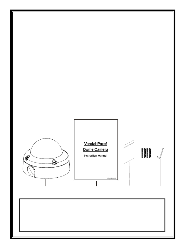
4. Contents
l.
for
3
12
A
B
Item Name of Part Quantity
1 Camera 1
2 Instruction Manual 1
3 Appurtenance Bag 1
A Screws 4
B L-Wrench 1
2
Page 4

5. Installation & Operation
1. Use the provided L-wrench; loosen the tamper-resistant housing
cover with screws still attached on the cover (Fig. 1).
L
Note: The
e
d
n
r
a
o
B
s
i
x
A
-
3
inner parts may differ depending on the camera model type.
s
i
x
A
-
3
Fig. 1
o
F
c
-
a
i
r
a
V
s
l
+
s
n
e
L
d
r
a
o
B
2. The unit has a factory installed side conduit entry and one may
adjust the cables to back conduit entry according to installation
requirement (Fig. 2).
Fig. 2
3. Set the mounting base onto the wall or ceiling and center it over the
mounting hole, using the supplied four retaining screws to secure the
main body (Fig. 3).
Fig. 3
3
I
R
Page 5

4. Camera Image Adjustment:
2-Axis – Set proper image by moving the camera module and set
the focus by turning the lens to the left or right direction.
3-Axis – First tilt then rotate the camera module to obtain desired
viewing angle, and then turn the horizontal adjustment ring to
correct the image and achieve proper orientation.
3
- Axis A d justme n t Guid e
Board Lens & Var i-Focal
T
o
p
p
o
T
t
t
l
l
i
i
T
T
Top
Camera
Module
Camera
Module
a
r
o
B
s
+
n
e
L
d
r
a
o
B
l
a
a
V
Camera
Module
c
o
F
-
i
r
Shade Facing Left
Shade Facing Top
Note: When adjusting 3-Axis Vari-Focal lens, before following the
Camera Image Adjustment setup, you must turn the horizontal
adjustment ring so that the shaded area
is facing toward you on the top
r left side. o
4
d
L
I
R
e
n
s
Horizontal
Adjustment
Ring
Horizontal
Adjustment
Ring
Horizontal
Adjustment
Ring
Page 6

5. When the camer a focus adjustment has been completed, use the
provided L-wrench to fasten the tamper-resistant housing to the
main body.
When using the side conduit cabling, it is suggested to cover the cables
6.
using metal covers (to prevent external damage and for waterproof
prevention), and wined the waterproof adhesive tape (P.T.F.E. THREAD
SEAL TAPE) onto the metal cover before installation.
7. Connect the video output to the monitor or other video device
through a 75 Ohms type coaxial cable and the DC-Jack or AC/
DC-Terminator to the power source.
Note: Powe
r adapter is sold separately.
To Monitor
To DC 12V Power Source
(
Option: AC 24V/ DC 12V Dual Model)
5
Page 7

8. Vari-Focal Dome Operation Guide
Once the picture appears on the monitor, open the cover and
adjust the lens wrench to “NEAR←→FAR”, get the view zoom that
you desire, and then adjust the focus wrench of the lens to obtain
the best picture. After adjustment, tighten both wrenches.
Switch Setting
DIP
Flickerless Function
Set switch-OFF/ F.L. to Flicker to enable flickerless function, in
this mode, the switch-AES/ OFF is auto disabled.
AGC-Hi/ AGC-Lo Function
Adjust the switch to AGC indicates AGC-Hi and OFF indicates
AGC-Low. AGC-Hi mode--The maximum AGC gain is approximately
26dB. AGC-Lo mode--The maximum AGC gain is approximately
16dB.
Auto Iris Function
When using an auto iris lens, the swi t ch - A E S / OF F should be in
the OFF position to disable the AES function. Adjust VR to the
proper level.
BLC Function
Set switch-OFF/ BLC to BLC to enable Back Light Compensation
(BLC) function.
6
Page 8

7
Page 9

6. Specification
According to the camera purchased, select and refer to the appropriate specification below:
Color Camera
NTSC: 768 x 494
PAL: 752 x 582
0Lux
1/3” Ultra Hi- Res.
Color CCD
(Sony Chipset)
180ma
Max.
440mA
max.
180mA
Max.
210Ma
Max.
1/3” Hi-Res.
Color CCD
(Sony Chipset)
0.3Lux/ F2.0 0.4Lux/ F2.0 0.5 Lux/ F2.0
F2.0
Vari-Focal Lens, Vari-Focal Lens with ICR, and Board Lens
180mA
Max.
440mA
Max.
180mA
Max.
210mA
Max.
Day
IR
On
IR
On
IR
Off
1/3” Color CCD
(Sony Chipset)
NTSC: 510 x 492
PAL: 500 x 582
0.3Lux/
F2.0
160mA
Max.
440mA
Max.
160mA
Max.
190mA
Max.
0.2Lux/
150mA
Max.
430mA
Max.
150mA
Max.
180mA
Max.
Image Device
Picture Elements
Resolution 380 TVL 470 TVL 550 TVL 330 TVL
Min. Illumination
S/N Ratio More than 48 dB
Electronic Shutter NTSC:1/60~1/100,000, PAL:1/50~1/110,000
Iris Control DC Drive (for Vari-Focal & Vari-Focal+ICR model)
Gamma 0.45
Gain Control Auto
Lens Furnished
(option)
White Balance Auto
Back Light Comp. On/ Off
Sync. System Internal.
Video Output 1 Vp-p/ 75 Ohms.
Power Supply DC12V±10% (optional: DC12V/ AC24V Dual)
Board Lens
Power
Consumption
Operating Tem p. -10℃ to 50℃
Board
Lens+IR
Vari-Focal Lens
Infrared Illuminator Module (for board lens type only)
Infrared Luminary 24 pieces IR-LED
Wavelength 850nm
Illuminate Distance 20M
8
1/4” Color CCD
(Sony Chipset)
NTSC: 510 x 492
PAL: 500 x 582
160mA
Max.
440mA
Max.
160mA
Max.
190mA
Max.
 Loading...